Analysis for Hydrodynamic Wedge-Platform Thrust Slider Bearing with Ultralow Surface Separation
Abstract
For the case of ultralow surface separation, in a hydrodynamic wedge-platform thrust slider bearing, the outlet zone and a portion of the inlet zone are in boundary lubrication, while most of the inlet zone is in the multiscale lubrication contributed by both the adsorbed boundary layer and the intermediate continuum fluid film. The present paper first presents the mathematical derivations for the generated pressure and carried load of this bearing based on the governing equation for boundary lubrication and the multiscale flow equation. Then, the full numerical calculation is carried out to verify the analytical derivations. It was found that the mathematical derivations normally have considerable errors when calculating the hydrodynamic pressure distribution in the bearing, owing to introducing the equivalent parameter λbf,e which is constant in the inlet zone; however they can be used to calculate the carried load of the bearing when the surface separation in the outlet zone is sufficiently high. The study suggests the necessity of the numerical calculation of the hydrodynamic pressure and even the carried load of this bearing. It is also shown that owing to the fluid-bearing surface interaction, the pressure and carried load of this bearing are significantly greater than those calculated from the classical hydrodynamic theory.
1. Introduction
There is an intrinsic very thin boundary layer (normally with the thickness no more than 10 nm) physically adsorbed to the solid surfaces in a hydrodynamic slider bearing [1, 2]. When the bearing surface separation is on the 1μm scale or greater, the adsorbed boundary layer effect is negligible, and the classical hydrodynamic theory [3] may be applied. It was found that only when the minimum bearing surface separation is lower than one hundred times of the thickness of the boundary layer, the boundary layer effect should be considered [4]. With the increases of the load, sliding speed, and/or the fluid film temperature, the bearing will work with the surface clearance on the same scale with the thickness of the boundary layer. For this case, the classical hydrodynamic theory fails, and new hydrodynamic theory needs to be developed by incorporating the boundary layer effect.
For the fluids with long-chain molecules, the boundary layer may be only monolayer with a considerable thickness, and it can be taken as a solid layer [5–9]. For this case, the analysis is simple just by adding the boundary layer thicknesses. We can apparently notice the effect of the residual boundary film for the low bearing surface clearance. For the fluids with short-chain molecules or simple fluids such as water, alcohol, and methane, the boundary layer on a sold surface may consist of several molecule layers in the range of the fluid-solid interaction, and its rheological properties including the local density and local viscosity are varied across the boundary layer thickness according to molecular dynamics simulation results [10–14]; this boundary layer should essentially be considered as a flowing layer under the entrainment of the moving surfaces. By equivalently treating the boundary layer as orientated normal to the solid surface, Zhang [15] developed the flow equations, respectively, for the two adsorbed boundary layers and the intermediate continuum fluid in the two-dimensional multiscale flow when the distance between the two solid surfaces is comparable to the boundary layer thickness.
Shao et al. [16] analyzed the multiscale hydrodynamic wedge-platform thrust slider bearing by using Zhang’s multiscale flow equations when the two bearing surfaces approached to one another, but there was still a continuum fluid film existing in the whole contact intervening the two boundary layers. Their analysis is obviously more advanced than the classical hydrodynamic analysis [3], which only considered the continuum fluid. It is applied for the condition of heavy loads and/or low sliding speeds. They found that when the minimum bearing surface separation is below 100 nm, the boundary layer effect significantly increases the hydrodynamic pressure and carried load of the bearing for the medium and strong fluid-bearing surface interactions.
When the bearing surface clearance is further reduced so that in the outlet zone the intermediate continuum fluid film vanishes and there is only the physically adsorbed boundary layer, the analysis by Shao et al. [16] will fail, and new mathematical analysis should be developed for this special model of the bearing. In this bearing with ultralow surface separation, the boundary layer in the outlet zone should follow the nanoscale flow equation; in the inlet zone area adjacent to the outlet zone, there is also only the boundary layer existing which should be described by the nanoscale flow equation; and in the other area of the inlet zone, there is still the multiscale flow incorporating both the boundary layer flows and the intermediate continuum fluid flow. The present paper attempts to address this bearing by developing the full mathematical derivation, though Zhang [17] has analyzed this specific mode of hydrodynamics in a line contact. Numerical calculation is also made to verify the accuracy of the derived mathematical equations for the pressure and carried load of the bearing. Important conclusions are drawn concerning the analysis and performance of this particular bearing.
2. Model of the Studied Bearing
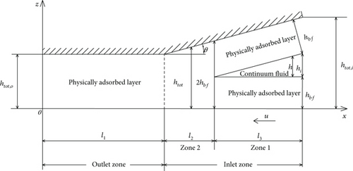
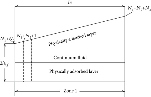
Figure 1 shows the hydrodynamic wedge-platform thrust slider bearing with ultralow surface separation studied in this paper. In this bearing, the surface separation in the outlet zone is so low (normally on the 1 nm scale) that only the physically adsorbed boundary layer exists (i.e., the intermediate continuum fluid film disappears) in the outlet zone; in the inlet zone area adjacent to the outlet zone, there is also only the physically adsorbed boundary layer because of the very low surface separation, but in the remaining area of the inlet zone occurs the multiscale hydrodynamics consisting of both the adsorbed boundary layer flows and the intermediate continuum fluid flow. This bearing model is new and deserves a proper study, as the classical (continuum) hydrodynamics fail for it.
Molecular dynamics simulation (MDS) [18–21] may be used to model the flow of the confined fluid in the nanoscale surface separation in the outlet zone, and it may also be used to model the flow of the adsorbed boundary layer in the multiscale hydrodynamic area in the inlet zone. This should be feasible if the bearing width is on the 1 nm or 10 nm scales. However, when the bearing width is on the micrometer or millimeter scales, MDS should be given up for modeling the molecular scale flow in the bearing owing to costing too long computational time and too large computer storage. This is often true so that the conventional multiscale scheme by using MDS [18–21] is not applicable for the present bearing model.
Fortunately, Zhang [15] derived the closed-form explicit flow equations, respectively, for the adsorbed boundary layer flows and the intermediate continuum fluid flow in the two-dimensional multiscale flow. These equations can be directly implemented for the multiscale hydrodynamic area in the inlet zone of the bearing. The nanoscale flow equation [22] can be implemented for the other area of the bearing, where only the boundary layer exists. These construct the frame of the present mathematical analysis for the studied bearing.
3. Theoretical Analysis
The analysis is based on the following assumptions for the simplification:
(1) The fluid is isoviscous and incompressible; (2) the two bearing surfaces are identical and perfectly smooth; (3) the fluid film thermal effect is negligible; (4) the side leakage of the bearing is negligible; and (5) no interfacial slippage occurs on any interface. Assumptions (1), (3), and (5) are correct for the case of very low sliding speeds and very light loads such as for microslider bearings. When the bearing clearance is ultralow, even the nanometer-scale surface roughness is comparable, and the surface roughness effect should be considered. This subject will be addressed in the following research. For the other factors deviating from the above assumptions such as the side leakage, the film viscous heating, or the wall slippage in a macrosize bearing, the correction factors can be introduced to modify the present results for the practical application.
3.1. Mathematical Derivations
3.1.1. For the Zone 1 of the Inlet Zone
Equation (1) is highly nonlinear. For the feasible integration of Equation (1), the parameter λbf in Equation (1) is taken as the equivalent constant value λbf,e = 2hbf/(khi), where k is constant and ranges between 0 and 2. This treatment should surely introduce some calculation errors. The direct numerical solution to Equation (1) afterwards is also obtained to verify the accuracy of the mathematical derivation based on this equivalent treatment.
3.1.2. For the Zone 2 of the Inlet Zone
3.1.3. For the Outlet Zone
3.1.4. Mass Flow Rate and Carried Load of the Bearing
3.2. Numerical Solution
For examining the accuracy of the derived equations in Section 3.1 based on the assumed equivalent value λbf,e, direct numerical calculations were also carried out based on Equations (1) and (17). This section describes the detailed numerical procedure.
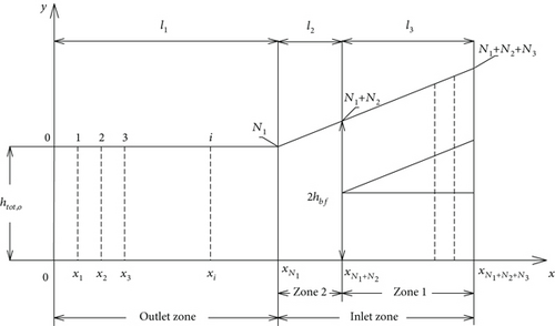
In Figure 2, the discretized points are, respectively, evenly distributed in the outlet zone, in the zone 2 and in the zone 1 with the total numbers (N1 + 1), (N2 + 1), and (N3 + 1).
3.2.1. Numerical Analysis for the Outlet Zone
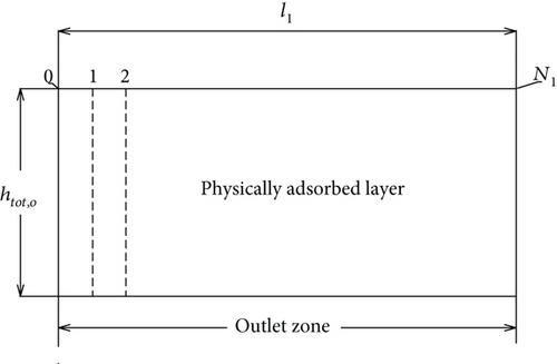
As shown above, the backward difference scheme can make the numerical results be easily obtained.
3.2.2. Numerical Solution for the Zone 2 of the Inlet Zone
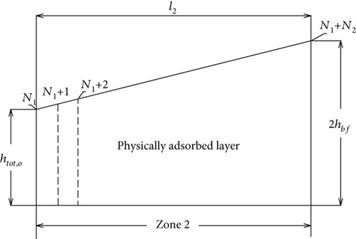
3.2.3. Numerical Solution for the Zone 1 of the Inlet Zone
3.2.4. Numerical Solution Procedure
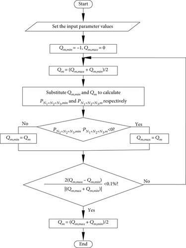
In the numerical calculation, the initial value of qm is chosen as that calculated from the classical hydrodynamic theory [3]. Then, the pressures on all discretized points can be calculated from the equations shown above, by starting the calculation from the exit of the bearing. The value of qm in the iteration will be changed until the following convergence criterion is satisfied: |2(Qm,max − Qm,min)/(Qm,max + Qm,min)| < 0.1%. Figure 6 shows the numerical solution procedure.
4. Calculation
The weak, medium, and strong fluid-bearing surface interactions were, respectively, considered. The input parameter values for these interactions are, respectively, shown in Tables 1–4.
| Interaction | Parameter | ||
|---|---|---|---|
| a0 | a1 | a2 | |
| Strong | 1.8335 | -1.4252 | 0.5917 |
| Medium | 1.0822 | -0.1758 | 0.0936 |
| Weak | 0.9507 | 0.0492 | 1.6447E-4 |
| Interaction | Parameter | |||
|---|---|---|---|---|
| m0 | m1 | m2 | m3 | |
| Strong | 1.43 | -1.723 | 2.641 | -1.347 |
| Medium | 1.30 | -1.065 | 1.336 | -0.571 |
| Weak | 1.116 | -0.328 | 0.253 | -0.041 |
| Interaction | Parameter | |||
|---|---|---|---|---|
| n0 | n1 | n2 | n3 | |
| Strong | 0.4 | -1.374 | -0.534 | 0.035 |
| Medium | -0.649 | -0.343 | -0.665 | 0.035 |
| Weak | -0.1 | -0.892 | -0.084 | 0.1 |
| Interaction | Parameter | ||||
|---|---|---|---|---|---|
| n | q0 | γ | hcr,bf,1(nm) | hcr,bf,2(nm) | |
| Strong | 8 | 1.2 | 1.5 | 40 | 80 |
| Medium | 5 | 1.1 | 1 | 20 | 40 |
| Weak | 3 | 1.03 | 0.5 | 7 | 14 |
5. Results
5.1. Validation of the Numerical Calculation
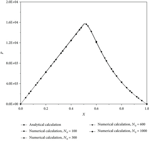
For validating the numerical calculation, the numerically solved pressures for different discretized points in the bearing are compared in Figure 7 with the classical hydrodynamic theory calculations [3] when the model of the bearing is assumed as classical (i.e., the fluid is Newtonian with the adsorbed boundary layer neglected). With the discretized points nearly evenly distributed in the bearing, it is shown that N0 = N1 + N2 + N3=1000 is sufficient for the numerical accuracy.
5.2. Validation of the Analytical Derivations for the Present Model of the Bearing
In the analytical derivations of the pressure and carried load of the present model of the bearing as shown above, it is critically important to assume the equivalently constant parameter λbf,e and to take htot = (htot,o + 2hbf)/2 to calculate the approximate and constant values of Cq2, Cy2, and S in the zone 2 of the inlet zone. These treatments will unavoidably cause the calculation errors. For estimating the accuracy of the analytical derivations for the present bearing, the calculations of the pressure from Equations (6), (14), and (19) are compared with the full numerically calculated pressures. In the numerical calculation, N0 = 1000.
Figure 8(a) compares the dimensionless pressure distributions in the present model of the bearing, respectively, analytically calculated and numerically solved for different fluid-bearing surface interactions for the same operating conditions. It is shown that for the weak and medium fluid-bearing surface interactions, there are only small differences between these two calculations; however, for the strong fluid-bearing surface interaction, there are significant differences between these two calculations. It is suspected that the analytical calculation errors should mainly be arising from the approximate calculations of Cq2, Cy2, and S (respectively, from Equations(40)–(42)) in the zone 2 of the inlet zone by putting htot = (htot,o + 2hbf)/2. As shown in Figure 1, if htot,o is very close to 2hbf, the surface separation in the zone 2 of the inlet zone is nearly constant, and it can be taken as htot = (htot,o + 2hbf)/2. In such a case, the calculation errors of Cq2, Cy2, and S in the zone 2 of the inlet zone should be small enough so that the accuracy of the analytical calculation is good.
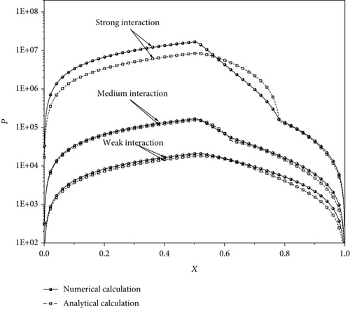
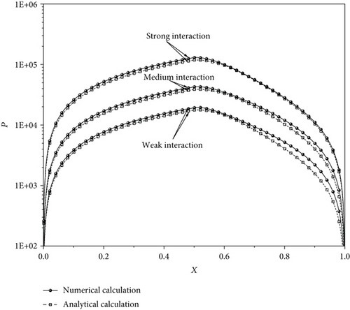
For justifying this suspect, we use htot,o = (2hbf)0.99 to recalculate the analytical pressures and make the similar comparisons in Figure 8(b). This chosen value of htot,o is very close to 2hbf, and it should substantially improve the accuracies of the analytical calculation. It is shown that for the strong interaction, the calculation error of the analytical equations is much reduced compared to those in Figure 8(a). Figure 8(b) verifies our conjecture.
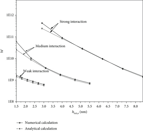
Figure 9 compares the analytically calculated dimensionless loads of the present model of the bearing (by Equation (22)) with those numerically calculated for different fluid-bearing surface interactions. It is shown that for the weak interaction, the accuracy of the analytical calculation is acceptable, and for the medium interaction, it is acceptable for htot,o ≥ 2.5nm, while for the strong interaction, it is acceptable for htot,o ≥ 4nm. The comparisons validate the value of the present analytical derivations.
5.3. Bearing Performances
This section presents the numerical calculation results for the hydrodynamic pressure and carried load of the present model of the bearing. In all these calculations, N0 = 1000.
5.3.1. Pressure Distribution
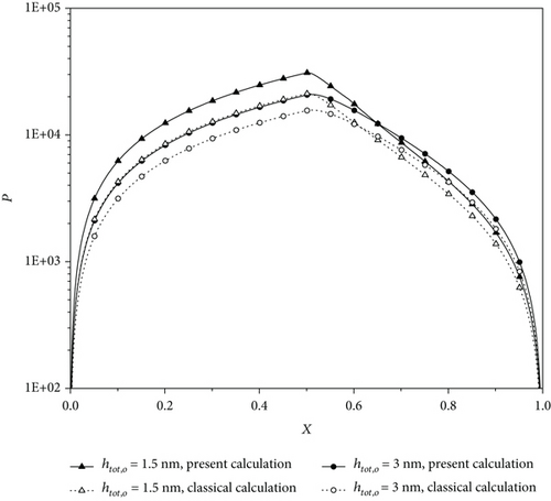
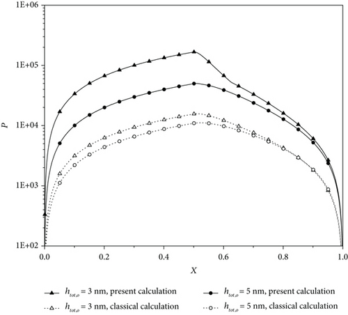
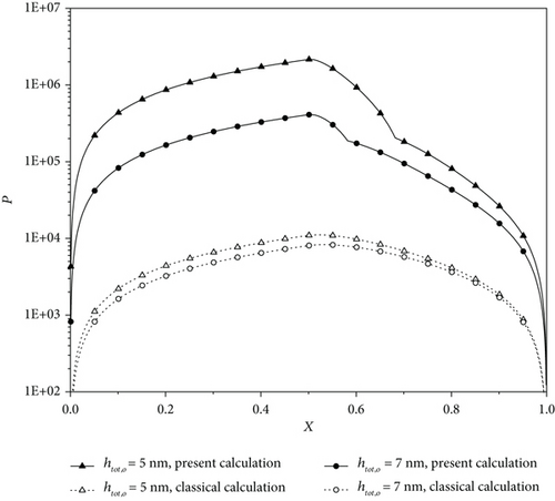
Figures 10(a)–10(c) show the dimensionless hydrodynamic pressure distributions in the present model of the bearing, respectively, for different fluid-bearing surface interactions and different bearing clearances. Compared to the classical hydrodynamic theory calculation, the present calculation shows that for the weak interaction and the outlet bearing clearances of 1.5 nm and 3 nm, the pressures in the bearing are very significantly increased due to the physically adsorbed boundary layers on the two bearing surfaces. For the medium and strong interactions, the pressure increases can, respectively, be 1 and 2 orders. These figures strongly indicate that the fluid-bearing surface interaction has a heavy influence on the pressures in the bearing.
5.3.2. Carried Load of the Bearing
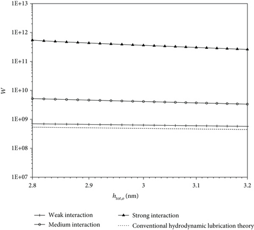
Figure 11 compares the calculated dimensionless carried loads of the present model of the bearing for different fluid-bearing surface interactions for the same operating conditions. For maintaining the model of the bearing for all these three interactions, the plotted range of htot,o is narrow. The weak interaction gives the load of the bearing a bit larger than that calculated from the classical hydrodynamic theory. The medium and strong interactions give the loads of the bearing, respectively, 1 and 3 orders larger than the classical hydrodynamic theory calculation. In the studied model of the bearing, owing to the ultralow surface separating and the resulting heavy influence of the physically adsorbed boundary layer on the bearing surface, the fluid-bearing surface interaction largely alters the bearing performance.
6. Conclusions
In a hydrodynamic thrust slider bearing, when the surface separation in the outlet zone is ultralow (e.g. on the 1 nm scale), in the outlet zone there is only the boundary layer physically adsorbed to the bearing surfaces, while in most of the inlet zone, there are the adsorbed boundary layers and the continuum fluid film. In this case, the bearing outlet zone is in the boundary lubrication, while most of the bearing inlet zone is in the multiscale lubrication. The classical analysis fails for this bearing owing to neglecting the adsorbed boundary layer.
The present study develops the mathematical analysis for the hydrodynamic wedge-platform thrust slider bearing with ultralow clearances by addressing this mode of lubrication. The nanoscale flow equation [22] describes the flow of the boundary layer in the outlet zone, and the multiscale flow equations [22] describes the flows of the adsorbed boundary layers and the intermediate continuum fluid film in the inlet zone.
The closed-form explicit equations have been derived, respectively, for calculating the hydrodynamic pressure and carried load of the studied bearing by making some simplifying assumptions, i.e., by introducing the equivalent parameter λbf,e for the multiscale hydrodynamic area and by using htot = (htot,o + 2hbf)/2 to calculate the values of Cq2, Cy2, and S in the boundary lubrication area in the inlet zone. The numerical calculations were also carried out to verify the accuracies of the derived analytical equations. It was found that for the weak fluid-bearing surface interaction, the accuracies of the analytical equations are acceptable; for the medium interaction, they are acceptable for htot,o ≥ 2.5 nm (htot,o is the surface separation in the bearing outlet zone), while for the strong interaction, they are acceptable for htot,o ≥ 4 nm. It was found that the errors of the derived analytical equations are mainly caused by using htot = (htot,o + 2hbf)/2 to calculate Cq2, Cy2, and S in the boundary lubrication area in the inlet zone.
The numerical calculations show that in the present model of the bearing with ultralow surface separations, even for the weak fluid-bearing surface interaction, the pressures are very significantly increased due to the physically adsorbed boundary layers on the two bearing surfaces; for the medium and strong interactions; the pressure increases can, respectively, be 1 and 2 orders; and the load-carrying capacity of the bearing is correspondingly increased by the fluid-bearing surface interaction.
Nomenclature
-
- a0, a1, a2:
-
- Constant
-
- Cy1:
-
-
- Cq1:
-
-
- Cy2:
-
-
- Cq2:
-
-
- D:
-
- Fluid molecule diameter
-
- F1, F2, ε:
-
- Parameters accounting for the noncontinuum effect of the adsorbed boundary layer
-
- h:
-
- Continuum fluid film thickness
-
- hcr,bf,1:
-
- Critical thickness for characterizing the rheological properties of the adsorbed boundary layer in the zone 1
-
- hcr,bf,2:
-
- Critical thickness for characterizing the rheological properties of the adsorbed boundary layer in the zone 2 or in the outlet zone
-
- hbf:
-
- Thickness of the adsorbed layer
-
- hi:
-
- Continuum fluid film thicknesses on the entrance of the bearing
-
- htot:
-
- Surface separation
-
- htot,i:
-
- Surface separation on the entrance of the bearing
-
- htot,o:
-
- Surface separation on the exit of the bearing
-
- Hbf,1:
-
-
- Hbf,2:
-
- hbf/hcr,bf,2
-
- k:
-
- Parameter for formulating λbf,e
-
- l1, l2, l3:
-
- Widths of the outlet zone, the zone 2 and the zone 1, respectively
-
- m0, m1, m2, m3:
-
- Constant
-
- n0, n1, n2, n3:
-
- Constant
-
- n:
-
- Equivalent number of the fluid molecules across the adsorbed layer thickness
-
- N0:
-
- N1 + N2 + N3
-
- N1 + 1:
-
- Number of the discretized points in the outlet zone
-
- N2 + 1:
-
- Number of the discretized points in the zone 2
-
- N3 + 1:
-
- Number of the discretized points in the zone 1
-
- p:
-
- Hydrodynamic pressure
-
- P:
-
- Dimensionless pressure, phtot,o/uη
-
- q0:
-
- Δj+1/Δj
-
- qm:
-
- Total mass flow rate per unit contact length through the bearing
-
- Qm:
-
- Dimensionless total mass flow rate, qm/(uhtot,oρ)
-
- S:
-
- Parameter accounting for the noncontinuum effect across the surface separation
-
- u:
-
- Sliding speed of the bearing
-
- w1,w2,w3:
-
- Load components, respectively, contributed by the outlet zone, the zone 2 and the zone 1
-
- W:
-
- Dimensionless load, w/uη
-
- x:
-
- Coordinate
-
- X:
-
- Dimensionless coordinate, x/(l1 + l2 + l3)
-
- y1, y2, y3:
-
- Integral constant, respectively
-
- θ:
-
- Wedge angle of the bearing
-
- γ:
-
- Exponent
-
- ρ:
-
- Fluid bulk density
-
- :
-
- Average density of the adsorbed boundary layer in the zone 1
-
- :
-
- Average density of the adsorbed boundary layer across the whole surface separation in the zone 2 or in the outlet zone
-
- η:
-
- Fluid bulk viscosity
-
- :
-
- Effective viscosity of the adsorbed boundary layer in the zone 1
-
- :
-
- Effective viscosity of the adsorbed boundary layer in the zone 2 or in the outlet zone
-
- ηline,j−1:
-
- Local viscosity between the jth and (j − 1)th fluid molecules across the layer thickness
-
- λbf:
-
- hbf/h
-
- λbf,e:
-
- 2hbf/(khi)
-
- Δj:
-
- Separation between the (j + 1)th and jth fluid molecules across the layer thickness
-
- Δx:
-
- Separation between the neighboring fluid molecules in the flow direction in the adsorbed boundary layer
-
- Δn−2:
-
- Separation between the neighboring fluid molecules across the layer thickness just on the boundary between the adsorbed boundary layer and the continuum fluid film
-
- δx,1:
-
- l1/N1
-
- δx,2:
-
- l2/N2
-
- δx,3:
-
- l3/N3
-
- ζ:
-
- (c/b)1/3l3tanθ
-
- ζx:
-
- (c/b)1/3(x − l1 − l2)tanθ.
Conflicts of Interest
The authors declare that there is no conflict of interest with this research.
Open Research
Data Availability
The data reported in this paper will be available from the corresponding author with reasonable request.


