Study on the Adaptability of Shield Tunnel Segments Orthogonal Crossing Grade III Loess Ground Fissure Section
Abstract
Taking the Xi’an rail transit line orthogonal crossing the ground fissure section as the engineering background, the structural properties and adaptability of the shield tunnel lining segment under the ground fissure environment are carried out. Using the finite element numerical simulation method, combined with the relevant model tests that have been carried out by predecessors, the damage characteristics of shield tunnel lining segment structure under the action of the ground fissure are revealed. The results show that shield tunnel structure is mainly shear deformation, with local bending deformation. Secondly, the principal tensile stress and principal tensile strain at the arch waist and arch foot of segment ring intersecting with ground fissure section are the largest. The relative dislocation between the rings of the shield tunnel near the ground fissure in the hanging wall is the largest, and the opening of arch top ring seam near the ground fissure in the footwall is the largest. Finally, the conventional shield tunnel lining segment structure cannot be directly used in the ground fissure site with a vertical dislocation of 200 mm.
1. Introduction
In recent years, the scale and speed of China’s urban rail transit construction is unprecedented. This makes the urban subway construction face the challenges of various special geological conditions, among which the special geological hazards of ground fissures are more serious [1]. Ground fissures exist in many countries in the world [2–7], especially in Xi’an, China, where the most famous geological disaster is ground fissure. Since the first ground fissure was discovered in Xi’an in 1959, 14 ground fissures have been formed, with a distribution area of about 250 km2 and a total length of more than 160 km. The length of the ground fissures exposed to the surface is more than 70 km, and they all cross the urban and suburban areas of Xi’an in the NEE direction [8]. Since the construction of Xi’an rail transit started in 2007, there have been many rail transit lines intersecting the ground fissure zone, in which the intersection angle between 80°∼90° is the most [9]. At present, in the construction of Xi’an metro, the ground fissure zone is passed through by the open or shallow buried tunnels [10–14], and the remaining sections are passed by the shield tunnel. However, a rail transit line involves tunnels with multiple construction methods, and the connection and conversion between these tunnels with different construction methods not only brings certain difficulties to the project, but also seriously affects the normal propulsion speed of the rail transit line. Based on the above reasons, this article attempts to use shield tunneling method to pass through ground fissure site. However, the ground fissure site is different from the general site. The dislocation of the hanging wall and footwall of the ground fissure will have an adverse impact on the shield segment lining structure. If the segment lining structure can adapt to a certain degree of dislocation of ground fissures to achieve effective waterproofing and the structural strength meets the requirements, the shield tunneling method can be used for tunnel construction; If the segment lining structure cannot withstand the dislocation of ground fissure, what are the damage characteristics and how to deal with them are practical problems faced by the rail transit engineering and academic circles, which are worthy of in-depth study. Therefore, based on Xi’an ground fissure engineering grade [15, 16] (as shown in Table 1), a three-dimensional finite element model of shield tunnel orthogonally crossing grade III ground fissure section is established. Through the analysis of the mechanical mechanism of the shield tunnel structure under the action of the exposed ground fissure, it provides a theoretical basis for the design and safe operation of the Xi’an metro shield interval tunnel under ground fissure site environment, which has important theoretical significance and engineering practical value.
| Maximum vertical dislocation (Amax) | Amax > 400 mm | 200 <Amax ≤ 400 mm | 100 < Amax ≤ 200 mm | Amax ≤ 100 mm |
|---|---|---|---|---|
| Engineering classification | I | II | III | IV |
2. Project Overview
The diameter of Xi’an Metro shield tunneling machine is 6.25 m. The outer diameter of segment lining is 6.0 m, and the inner diameter is 5.4 m. A single segment ring is 1.5 m long and 0.3 m thick, which is composed of six segments, including one capping block, two adjacent blocks and three standard blocks. Staggered joint assembly is adopted between segment rings, which are connected by grade 6.8 ordinary bolts, and segment lining is made of C50 concrete.
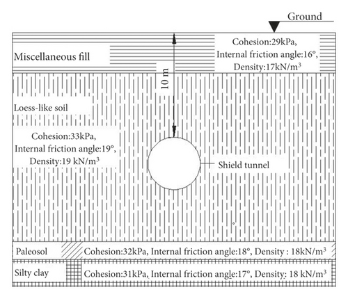
The f7 ground fissure site is selected as the simulation object in this model. The stratum profile of shield tunnel crossing ground fissure is shown in Figure 1. Among them, the stratum structure around the tunnel is mainly loess-like soil (), and the mechanical properties of each layer of soil are similar. In order to improve the convergence speed, it is simplified as a kind of soil treatment in the numerical simulation. The physical and mechanical parameters are shown in Table 2.
| Material | Model | Density kN (m3) | Poisson’s ratio | Cohesion kPa | Internal friction angle | Elastic modulus (MPa) |
|---|---|---|---|---|---|---|
| Soil | Modified Mohr–Coulomb | 19 | 0.35 | 33 | 19° | 27 |
| Grouting layer | Elastic | 21 | 0.25 | — | — | 1000 |
| Segment lining | Elastic | 25 | 0.2 | — | — | 34500 |
3. Calculation Model
3.1. Model Building
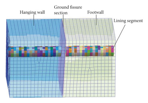
Based on midas GTS NX finite element software, a three-dimensional numerical model of shield tunnel orthogonal to the ground fissure section at 90° was established. Considering the boundary effect, the size of the stratum model is taken as length × width × height = 60 m × 42 m × 34 m, as shown in Figure 2. Among them, the entire tunnel is composed of 40 segment rings, and the distance between the arch top of the shield tunnel and the ground surface is 10 m, as shown in Figure 1. Starting from the left boundary, the first to 20th rings are located in the hanging wall of the ground fissure, and the 22nd to 40th rings are located in the footwall of the ground fissure, of which the 21st ring is orthogonal to the ground fissure. In addition, a grouting layer (the grout after 28 days of hardening) is set between the segment lining and the surrounding soil.
3.2. Ground Fissure Simulation and Calculation Condition
This numerical simulation mainly focuses on the structural properties of shield tunnel segment lining under the action of ground fissure dislocation, so it ignores the influence of stratum instantaneous displacement, stress release and postconsolidation deformation caused by shield excavation, as well as the disturbing influence of grouting behind the segments on the surrounding soil.
| Cohesion (c) (kPa) | Internal friction angle (φ) | Normal stiffness (Kn) (kPa) | Tangential stiffness (Kt) (kPa) | |
|---|---|---|---|---|
| 10 | 15° | 280 | 280 | |
3.3. Segment Joint Simulation
Segment joints mainly control the structural mechanical properties of shield tunnels. Considering the calculation efficiency and the influence of the segment joint, the segment joints adopt the shell interface model, that is, the segments and segment rings are connected through shell contact element. In addition to three translational degrees of freedom in the coordinate axis direction of the element coordinate system, the shell contact element has one more rotational degrees of freedom along the longitudinal direction of the tunnel. After the force is applied, the node will produce contact forces in three directions and one axial bending moment, which can more truly reflect the mechanical behavior of the connecting bolts between the segments and between the segment rings.
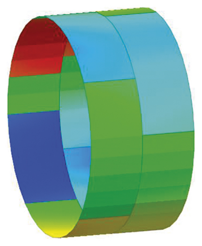
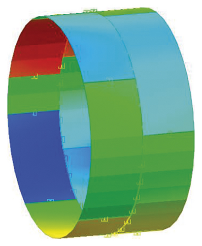
According to the research of Gijsbers and Hordijk, the shear stiffness of the segment joint largely depends on the applied normal force, which can usually be assumed to be 106 kN/m [18]. Each segment ring of model shield tunnel is composed of 6 segments, and the staggered angle of two adjacent rings is 22.5° when the model shield tunnel is assembled in staggered seams. Taking the two rings as an example, the segment assembly model is shown in Figure 3 and segment joint model is shown in Figure 4.
3.4. Material Constitutive Relationship and Calculation Parameters
Due to the characteristics of nonuniformity, anisotropy, and dilatancy of geotechnical materials, it can be said that no model can fully and accurately express these characteristics of geotechnical materials. In order to simulate the displacement of soil more accurately, Modified Mohr-Coulomb model is used for analysis. The physical and mechanical parameters of relevant materials refer to the research results of reference [19, 20], in which the elastic modulus of the segment lining is C50 concrete standard elastic modulus value, and the grouting material is calculated according to the elastic modulus after permanent consolidation, taking 1 GPa. All the above calculation parameters are shown in Table 2.
4. Analysis of Calculation Results
4.1. Parametric Analysis
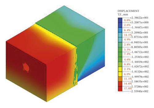
In the finite element analysis, when the initial stress field parameter k0 is not considered, the stress of each node of the finite element model element is zero. The final model vertical displacement cloud map is obtained, as shown in Figure 5. It can be seen from the cloud image that the maximum vertical displacement of the hanging wall of the final model is 25.6 cm, which is 5.6 cm larger than the actual settlement of 20 cm. Therefore, it will have a certain impact on the final calculation results. Especially for deeper and thicker soil layers, this additional deformation will be greater, which will have a more adverse impact on the final simulation results.
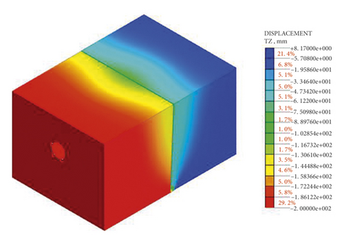
When the initial stress field parameter k0 is considered in the numerical analysis, the final model vertical displacement cloud map is obtained, as shown in Figure 6. It can be seen from the cloud map that the strata subsidence of the hanging wall is consistent with the actual situation. Therefore, in the numerical calculation of the interaction between ground fissure and tunnel structure, the initial stress field parameter k0 should be considered.
4.2. Analysis of Shield Tunnel Displacement
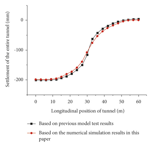
By comparing the numerical simulation results of shield tunnel settlement with the relevant model test results that have been carried out by Huang and Gou [21, 22], as shown in Figure 7. It can be seen from the figure that the numerical simulation results are basically consistent with the model test results, indicating the correctness of the established model. Secondly, it can be seen from the figure that the tunnel presents bending deformation as a whole in the longitudinal direction. The maximum settlement of the whole tunnel appears at the left boundary of the hanging wall, while the shield tunnel at the right boundary of the footwall has produced a certain amount of warpage. In addition, it can be seen from the slope of the settlement curve that the shield tunnel close to the ground fissure has a relatively large differential settlement, and the shield tunnel far away from the ground fissure basically shows overall settlement, indicating that the lining structure of the shield tunnel in the uneven settlement section near the ground fissure is most vulnerable to damage.
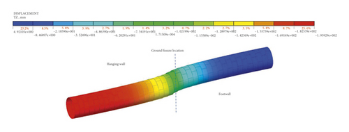
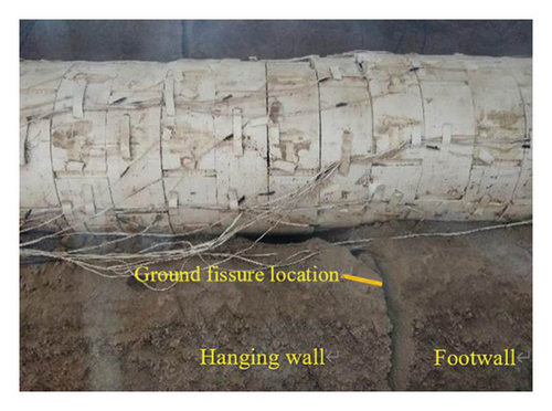
The settlement cloud map of the shield tunnel is shown in Figure 8. It can be seen from figure that the shield tunnel near the ground fissure produces large shear deformation. The amount of dislocation between the segment rings of the tunnel located in the hanging wall is significantly greater than that in the footwall, and the shield tunnel located in the hanging wall near the ground fissure presents a ladder shape in the longitudinal direction due to the inter-ring dislocation. In addition, the longitudinal affected range of tunnel lining structure near the ground fissure is roughly 6 rings at the hanging wall and 5 rings at the footwall. The above analysis results are basically the same as the model test result of Gou [21], in which the settlement deformation of the shield tunnel at the ground fissure observed after the model excavation is shown in Figure 9.
4.3. Analysis of Surface Cracks of Shield Tunnel
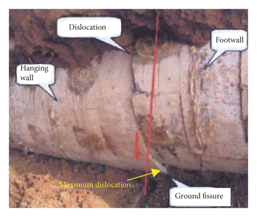
If cracks appear on the outer surface of shield tunnel lining segments, it will have an adverse impact on the durability of shield tunnel. Therefore, it is analyzed whether structural cracks appear on the outer surface of shield tunnel segments under the action of ground fissure. According to the theory of concrete structure, if the maximum principal tensile strain exceeds the ultimate tensile strain of concrete, it can be judged that the concrete is cracked. As shown in Figure 10, according to the cloud diagram of the principal strain on the outer surface of the shield tunnel lining segment, it can be seen that the maximum principal tensile strain occurs at the arch foot of the 21st ring intersecting with the ground fissure, and its value is about 0.0004, followed by the vicinity of the arch waist, and its value is about 0.00023, both of which are greater than the ultimate tensile strain of concrete (εtu = 0.00015). Therefore, there will be cracks around the arch waist and arch foot of the 21st ring. This is the same as the model test result of Huang [22], in which the outer surface crack of the shield tunnel at the ground fissure observed after the model excavation is shown in Figure 11.

4.4. Principal Stress on the Outer Surface of Shield Tunnel
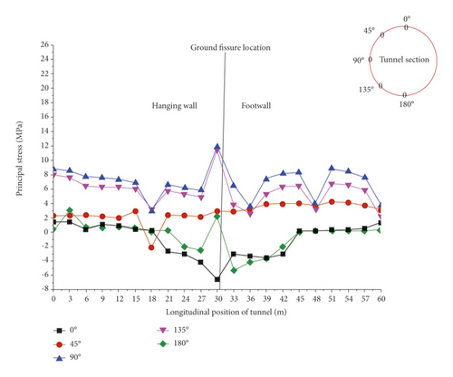
The principal stress on the outer side of the entire tunnel is shown in Figure 12. It can be seen from the figure that the principal tensile stress of the arch waist (90°) and arch foot (135°) of the entire shield tunnel is relatively large, in which the principal tensile stress of the arch waist and arch foot of the 21st ring intersecting with the ground fissure is the largest, 12.5 MPa and 12.2 MPa, respectively. At the same time, the principle compressive stress of the arch top of shield tunnel located in the hanging wall and the arch bottom of shield tunnel located in the footwall is relatively large, and the maximum principal compressive stress is 7.1 MPa. In addition, the above principal stresses have the same variation law along the longitudinal direction of the shield tunnel, and they are all abrupt changes at the ground fissure.
4.5. Opening between Segments
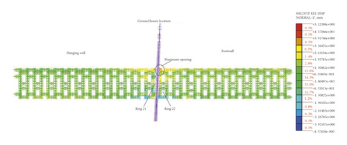
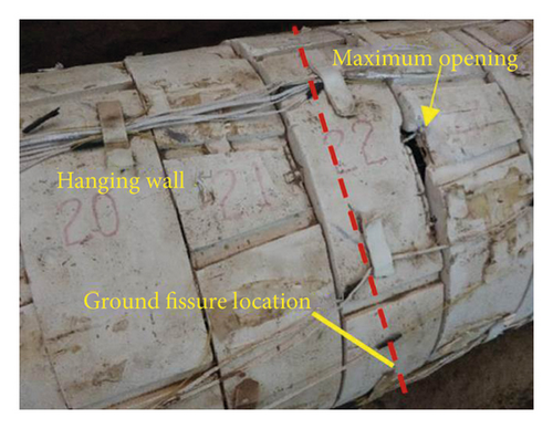
The relative displacement cloud map (normal direction) of the shell interface between the segments is shown in Figure 13. It can be seen from the figure that the arch top opening between the 17th ring and the 24th ring is all greater than 1 mm, in which the arch top opening between the 21st ring (at the ground fissure) and the 22nd ring in the footwall is most obvious, 5.2 mm. The above results are basically the same as the model test result of Gou [21], which the maximum opening between segment rings of arch top of shield tunnel at the ground fissure observed after the model excavation is shown in Figure 14. Since the water stop at the joint between segments is achieved by squeezing the water stop tie between adjacent segments, the excessive opening amount leads to the failure of normal anastomosis and compaction of the water stop tie between adjacent segments.
4.6. Dislocations between Segment Rings
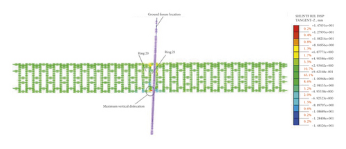
The relative displacement cloud map (tangential direction) of the shell interface between the segments is shown in Figure 15. It can be seen from the figure that the arch bottom relative dislocation between the 20th ring and the 21st ring in the hanging wall is the most obvious, about 14.7 mm, while the inter-ring dislocations in other parts of the shield tunnel are smaller. The above results are basically the same as the model test result of Huang [22], in which the maximum dislocation between segment rings of arch bottom of shield tunnel at the ground fissure observed after the model excavation is shown in Figure 11. Referring to the research results of reference [23], when the dislocation between the segments reaches 12 mm, the maximum stress in the tension zone of the connecting bolt between the segments exceeds the yield stress, and the connecting bolt enters plasticity.
5. Research on Countermeasures
5.1. Countermeasures
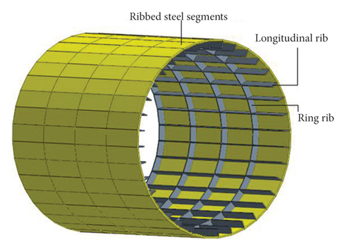
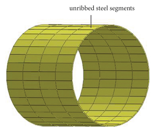
According to the damage characteristics of shield tunnel under the action of grade III ground fissure, two measures are tried to replace concrete segments with steel segments and increase the stiffness of the segment joint, and the shear stiffness of segment joint is 107 kN/m. In addition, in order to further explore the mechanical performance of steel structure segments after setting ribs, the three-dimensional finite element models of steel lining segment with two different cross-sections are established, as shown in Figure 16. The specific calculation parameters are shown in Tables 4 and 5.
| Material medium | Yield strength, fy (MPa) | Density, ρ (kN⋅m−3) | Poisson’s ratio, μ | Elastic modulus, E (MPa) |
|---|---|---|---|---|
| Steel segment | 345 | 78 | 0.3 | 206000 |
| Material medium | Material type | Segment thickness (mm) | Rib height (mm) | Rib thickness (mm) | Longitudinal rib spacing (°) | Ring rib spacing (mm) |
|---|---|---|---|---|---|---|
| Ribbed steel segments | Q345B | 50 | 250 | 20 | 10 | 750 |
| Unribbed steel segments | Q345B | 50 | — | — | — | — |
5.2. Analysis of Calculation Results
After the plastic deformation, the steel will break in the form of flow, which satisfies the fourth strength theory in material mechanics. Therefore, the analysis based on the fourth strength theory will make the results more consistent with the reality. Since the Von-mises stress in the finite element postprocessing results is the equivalent stress obtained by comprehensively considering the first, second, and third principal stresses according to the fourth strength theory, the Von-mises stress can be used to represent the complex stress state under the combined action of different internal forces, and through the maximum value of VON-MISES stress can determine the most dangerous area in the entire model.
The VON-MISES stress cloud diagram is shown in Figures 17∼18. The maximum Von-mises stress of the unribbed steel segment appears at the arch bottom position of the 21st ring (ground fissure position), which is 170 MPa. The maximum Von-mises stress of the ribbed steel segment also appears at the arch bottom position of the 21st ring, with a size of 145 MPa. Compared to the unribbed steel segment, The Mises stress of the ribbed steel segment is reduced by about 17%, which shows that the stress state of the ribbed steel segment is more ideal. In addition, the maximum Von-mises stress of two kinds of steel structure segment with different cross section is less than the yield stress (345 MPa), which indicates that under the action of grade III ground fissure, the two kinds of steel lining segment are in an elastic state.


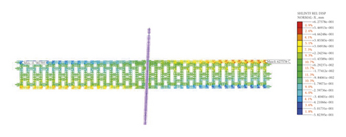
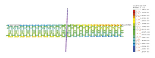
The relative displacement cloud diagram (normal direction) of the shell interface between the steel segments is shown in Figures 19∼20. It can be seen from the figure that the openings between the rings of two kinds of steel lining segments are basically the same are basically the same, and the maximum openings are both located at the arch top circumferential seam at the right boundary of the footwall, respectively 0.6 mm and 0.5 mm. In addition, the opening amount of the circumferential seam at the arch bottom of the 1st-16th ring in the hanging wall and the circumferential seam at the arch top of the 26th-40th ring in the footwall has increased, while the extrusion amount of the circumferential seam at the arch top of the 1st-16th ring in the hanging wall and the circumferential seam at the arch bottom of the 26th-40th ring in the footwall has increased. This shows that when the stiffness of the segment joint increases, the overall rigidity of the shield tunnel will increase, and the deformation of shield tunnel will change from “mainly shear deformation” to “mainly longitudinal overall bending deformation.”
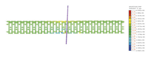
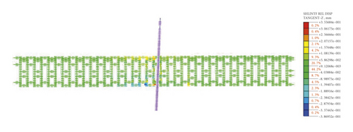
The relative displacement cloud diagram (tangential direction) of the shell interface between the steel segments is shown in Figures 21∼22. It can be seen from the figure that relative dislocations between the rings of two kinds of steel lining segments are basically the same, and the maximum dislocation amount both occurs between the 20th ring and the 21st ring, which is 0.46 mm and 0.36 mm respectively. The above results indicate that improving the stiffness of the segment joint can effectively reduce the dislocation between segment rings caused by ground fissure activity.
6. Conclusion
- (1)
In the numerical analysis, if only the gravity field is considered and the initial stress field parameter k0 of the model soil layer is not considered, the final vertical settlement of the hanging wall of the ground fissure is larger than the actual settlement. If the initial stress field parameter k0 is considered, the final vertical settlement of the hanging wall of the ground fissure is the same as the actual settlement. In addition, the numerical simulation results show that the areas with obvious differential subsidence of the stratum are concentrated near the ground fissure. The strata in the hanging wall are dominated by overall settlement, and the local strata in the footwall appear unevenly rising.
- (2)
Under ground fissure dislocation, the deformation mode of the shield tunnel orthogonal crossing the exposed ground fissure is mainly shear deformation, and the shear deformation of the shield tunnel located in the hanging wall near the ground fissure is the most obvious. Dislocation between the segment rings of the tunnel located in the hanging wall is significantly greater than that in the footwall, and the longitudinal affected range of tunnel lining structure near the ground fissure is roughly 6 rings at the hanging wall and 5 rings at the footwall.
- (3)
The principal tensile stress and principal tensile strain of the arch waist and arch foot of the 21st ring intersecting with the ground fissure is the largest, in which the maximum principal tensile strain exceeds the ultimate tensile strain of the concrete (εtu = 0.00015). While the principle compressive stress of the arch top of shield tunnel located in the hanging wall and the arch bottom of shield tunnel located in the footwall is relatively large, in which the maximum principal compressive stress is less than the ultimate compressive strength of concrete.
- (4)
The relative dislocation between the 20th ring and the 21st ring in the hanging wall is the largest, 14.7 mm, which will cause the yield of the connecting bolts between the rings. At the same time, the arch top opening between the 21st ring and the 22nd ring in the footwall is the largest, 5.2 mm, which will cause the damage of water stop at this place.
- (5)
Aiming at the damage characteristics of conventional shield tunnels under the action of grade III ground fissures, countermeasures are proposed and numerical simulations are carried out. The numerical results show that compared with the conventional shield tunnel, the mechanical performance of the shield tunnel after the measures has been significantly improved, and the corresponding measures taken are effective.
Conflicts of Interest
The authors declare that they have no conflicts of interest.
Open Research
Data Availability
The data used to support the findings of this study are included within the article.


