Research on High-Speed Railway Communication Strategy Based on LIFI Technology
Abstract
In order to improve the effect of high-speed railway communication, this paper studies the high-speed railway communication strategy combined with LIFI technology and improves the effect of high-speed railway communication through intelligent communication methods. Moreover, this paper studies the access point allocation problem in indoor LiFi/WiFi hybrid network, fully considers the dynamic change of network load, and introduces a dynamic load balancing algorithm that determines AP allocation in hybrid network based on the data transmission rate as the switching threshold. In addition, this paper proposes two AP allocation methods, such as dynamic switching threshold and minimum data rate constraint, to construct a reliable high-speed railway communication model. The experimental results verify that the high-speed railway communication strategy based on LIFI technology proposed in this paper can effectively improve the high-speed railway communication effect.
1. Introduction
The simulation modeling of the wireless channel is the premise of wireless communication system research. For special scenarios such as high-speed railways, the construction of simulation scenarios and the modeling of wireless channels are indispensable steps. Although the theoretical wireless channel model cannot perfectly reproduce the extremely complex channel state in the real environment, the wireless channel modeling parameters measured according to the real environment construction and statistical results can more truly reflect the rationality and effectiveness of various key technologies in the high-speed rail environment. However, at present, most of the research on high-speed rail 5G wireless communication is based on a single scenario and only considers modeling the Rice channel with invariant parameters [1] or directly modeling the Rayleigh channel [2]. Neither of these two types of simulations can reveal the actual situation of the high-speed rail, and thus cannot reflect the real performance of the key technologies of high-speed rail wireless communication.
There are abundant multipaths in the high-speed rail environment. To eliminate the multipath effect, the current high-speed rail wireless communication technology usually adopts the orthogonal frequency division multiplexing (OFDM) technology to convert the frequency-selective channel into a series of parallel channels through serial-parallel conversion. And the orthogonal frequency flatness channel improves the decoding success rate and thus the effective transmission efficiency. Because OFDM technology has the advantages of high spectrum utilization and anti-multipath fading and can be combined with various multiple access technologies, OFDM technology will continue to be used in high-speed rail wireless communication systems. However, considering the fast time variability of the channel, relatively many channel parameters need to be estimated. In order to simplify the estimated parameters, there are usually two models that transform the direct estimation problem of time-varying channels into the estimation problem of finite parameters: one is Gauss–Markov model (Gauss–Markov), also known as autoregressive (Auto.regressive), AR model [3]; the other is the Basis Expansion Model (BEM) [4], this method uses a linear combination of a set of basis functions to fit the time-varying channel, that is, each basis function is multiplied by different The correlation coefficient converts the estimation problem of the channel impulse response into the estimation problem of the base coefficient. The basis functions that can be selected include: complex exponential basis, polynomial basis, wavelet basis, and discrete ellipsoid sequence basis [5].
The railway mobile communication network optimization system analyzes the call records and OIC data of online users through the data collected in real time, integrates daily optimization, special optimization, and user-level optimization, and accurately, comprehensively, and reliably reflects the current network service quality. Assist network optimization and maintenance personnel to locate network problems, in a timely manner, determine optimization ideas, and systematically carry out optimization work. At the same time, functions such as network evaluation and geographic graphic display are realized, which improves the efficiency of network optimization and reduces the difficulty of network optimization. The high-speed rail mobile communication network optimization system interfaces with the network optimization platform and directly calls the data or analysis results of the network optimization platform [6]. The system not only realizes the daily KPI optimization analysis of professional network management, but also carries out multi-level tracking and positioning analysis for single base station, single cell, single carrier frequency, and single user, making network optimization work more targeted and accurate. Through a large amount of real-time CDR data, combined with the platform-specific pilot pollution, search window, neighbor relationship, abnormal release, CFC, and other special analysis, problems in the network can be found in a short time. The main task of the high-speed railway mobile communication network optimization system design stage is to complete the definition of the system architecture according to the demand analysis [7]. The system construction requires that it can adapt to the later business expansion. Some functional requirements are scalable, such as system functions, and the color of indicators displayed in each system required by users can be configured [8]. At this stage, if the design of the system structure is too customized, the scalability of the system will be weak, which will bring a huge burden to the later maintenance, increase the maintenance cost, and even cause the system life to be too short. On the contrary, the system structure is too flexible and general, which will inevitably increase the difficulty of system implementation and increase the complexity of the system [9].
The beamforming technology in the high-speed rail scenario can not only assist the on-board radio to perform handover, but also can be used to improve the transmission performance. While helping the system to obtain array gain, it can also combine other spatial transmission technologies to obtain diversity or multiplexing gain. In order to improve the transmission reliability, the multi-antenna eNodeB can use the space-time block code (STBC) [10] to obtain the transmit diversity gain and simultaneously use the beamforming technology to obtain the beamforming gain. Generally speaking, STBC requires that the element spacing of the eNodeB antenna array is large enough to ensure the fading independence of multipath components to obtain the maximum diversity gain. For example, for a uniform linear array (ULA), the element spacing should be 5 times the carrier wavelength to 10 times [11]. In contrast, beamforming techniques require the element spacing of the antenna array to be half a wavelength to implement the selection of the angular domain. Since these two technologies have different requirements on the spacing of antenna array elements, combining STBC with beamforming technology faces challenges. Reference [12] proposed a beamforming mechanism combined with STBC, and reference [13] proposed a beam switching mechanism combined with STBC. The performance of the beamforming mechanism combined with STBC is analyzed under some specific conditions. For example, reference [14] assumes imperfect channel information at the transmitter, reference [15] assumes a correlated MIMO fading channel, and reference [16] assumes The scenario of cooperating base station. The methods for generating the beamforming weight vector in the combination algorithm given in the above literature are all based on the decomposition of the covariance matrix of the channel. This method is obtained by using the largest eigenvector of the channel covariance matrix as the beamforming weight vector. Higher signal-to-noise ratio. It is a relatively simple method to calculate the beamforming weight vector based on DOA [17]. Reference [18] proposed that in a wireless environment with a small angular spread, the beam should not be directed toward the user DOA in order to ensure the maximum array gain, but a pair of beams should be generated to symmetrically fall on both sides of the user DOA. In reference [19], this combining mechanism is applied to the indoor communication environment; instead of using only a single antenna array above [20], divides an antenna array into two sub-arrays, and calculates the achievable array gain, followed by this assumption is also extended to systems with more than three transmit antennas.
This paper combines LIFI technology to study the high-speed railway communication strategy, improves the high-speed railway communication effect through intelligent communication methods, and promotes the improvement of high-speed railway communication technology.
2. LiFi Technology
2.1. Dynamic Load Balancing of LiFi/WiFi Hybrid Network
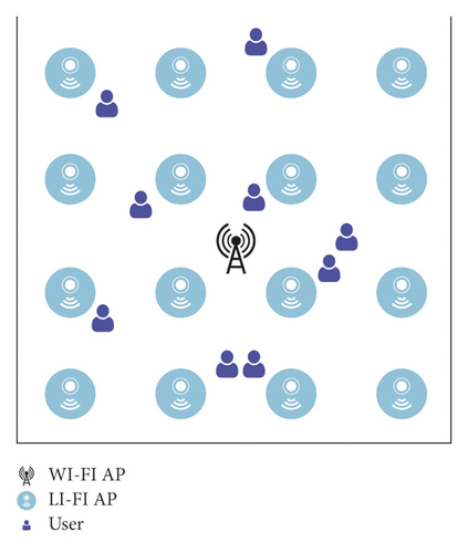
Considering the application scenario of indoor visible light communication, a hybrid network model of indoor LiFi and WiFi is constructed, as shown in Figure 1. 16 LiFi APs and 1 WiFi AP are deployed, and each LiFi AP consists of multiple LEDs. We assume that all photoelectric detectors (PD) are vertically upward facing the ceiling, and the incident angle of the optical transmission link is equal to the radiation angle. Each LiFi AP covers a limited area, which is an attocell network. All LiFiAPs reuse the same frequency band. Combined with the actual needs of high-speed railway communication, the network system is constructed, and multiple sensors are used for data processing. The next part of this paper will study the algorithm to improve the dynamic load balancing of system operation. Subsequent studies consider the effect of co-channel interference.
Among them, m is the Lambertian radiation series, Ap is the effective receiving area of the receiver photodetector, ri is the horizontal distance between the user and APi, and h is the vertical distance between the user and APi.
Among them, ηpd is the response rate of the receiving end PD, BL is the modulation bandwidth of the LiFi network, N0 is the noise power spectral density, Hu,a is the channel gain between user u and LiFiAP a, and Hu,else is the channel gain between user u and the interfering LiiAP.
In the LiFi network, due to the dense arrangement of access points, it can provide higher regional frequency spectral efficiency performance, but it also causes serious co-channel interference problems. The introduced partial frequency reuse scheme can effectively suppress the CCI problem, but in addition, the LiFi network also has the problem that the light is easily blocked and the network is interrupted. In this chapter, the method of time division multiplexing (TDMA) is used to realize multiuser access. Using a fairer scheduling algorithm, users served by LiFiAP share equal time resources.
Among them, d is the distance between the transmitter and receiver in m; the carrier frequency f is 2.4 GHz.
The topology of a communication network plays a major role in determining the communication mode between interconnected devices. Specifically, the fault tolerance and fault diagnosis characteristics of the system are determined by the connectivity of nodes in the network; the regularity of the network greatly affects the complexity and reorganization characteristics of algorithms such as communication routing.
Considering the case of multiple users, we assume that electric power is equally allocated to each subcarrier, and carrier resources are dynamically allocated to each user for signal transmission. Using a proportional fair scheduling algorithm, users served by WiFiAP share equal bandwidth resources. Then the bandwidth Ba = Bx/NR is allocated to each user by the WiFi AP, where NR is the number of users served by the WiFi AP.
2.2. Dynamic Load Balancing Switching Scheme
We assume that the complete set of users is U, the set of users served by LiFi is UL, and the set of users served by WiFi is UR. NL is the number of users in set UL, and NR is the number of users in set UR. S is the number of randomly generated users. represents the AP assigned to user u in the n − 1 state. The central unit can calculate and from the channel state information between user u and LiFi and WiFi APs. In each state, in order to make full use of the higher spectrum resources of the LiFi network, users are preferentially allocated to LiFiAPs. Therefore, the initial value of the state is UL = U, UR = {∅}, NL = s, NR = 0.
Among them, is the number of users served by LiFi AP wL,u.
According to the AP allocation method FT, DT, or MDRC, the serving AP of the user can be determined, and the UL, wL,u, and UR can be determined. The central processing unit connects the corresponding users to the LiFi network according to U and wL,u and connects the corresponding users to the WiFi network according to UR.
2.3. System Model
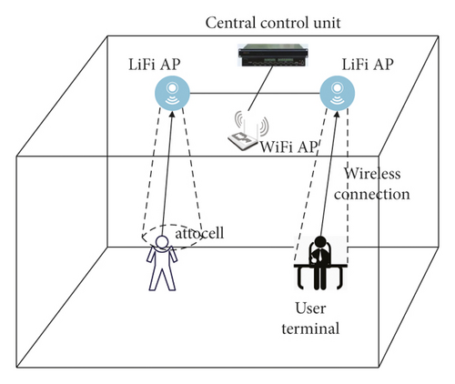
An indoor dynamic scenario is considered, multiple LiFi APs and one WiFi AP are deployed, which is denoted by APi, where i = 0 represents that the access point is WiFiAP, i = 0 represents that the access point is WiFiAP, and Ni is the number of users in the APi coverage unit. The WiFi AP covers all indoor areas, each LiFi AP covers a limited area, and the user is in the mixed network coverage area as shown in Figure 2.
The DC-biased optical orthogonal frequency division multiplexing is used as the downlink information transmission scheme to ensure that the real-valued signal is transmitted to the receiving end. Therefore, at least half of the subcarriers must be used to achieve Hermitian symmetry, where Ni is the number of users served by the LiFiAP.
Among them, ψa and ψb are two data rate thresholds. When the user’s available data rate is less than ψa, the user’s data rate communication requirements cannot be met. However, when the data rate exceeds ψb, it can no longer improve user satisfaction. The data rate is between the two thresholds, and there is a positive correlation between user satisfaction and the data rate.
2.4. Access Point Selection Scheme Based on Reinforcement Learning
Reinforcement learning is an online learning algorithm that learns an optimal action strategy to obtain the maximum reward by continuously improving the agent’s behavior in the interaction between the agent and the environment.
When the train passes through the mountains, the high-speed rail tunnel can ensure the stable and high-speed operation of the train, and the tunnel scene has become one of the typical high-speed rail scenes. Common tunnels are structurally limited, with tunnels ranging in size from a few hundred meters to several kilometers, depending on the surrounding geography. Considering the unique structure of high-speed rail tunnels, the radio wave propagation inside the tunnel is very different from other high-speed rail scenarios. The wireless signal will interact with the abundant effective scatterers inside the tunnel, and multiple reflections, diffractions, and transmissions will become the main propagation mechanisms inside the tunnel. Therefore, it is necessary to realize the information transfer between the agent and the environment.
The process of the agent interacting with the environment is divided into the following steps: (1) The agent perceives the environmental state st at time t. (2) For state st and expected immediate reward Rt, the agent performs action at according to a certain strategy. (3) The action performed by the agent acts on the environment. The environment changes to update the state to st+1 and gives an immediate reward Rt to feedback to the agent, and the time t is updated to t + 1. By repeating the above steps continuously, the agent finally learns the optimal action strategy under the given goal.
Among them, Ps,a(s′) is the transition probability from the initial state s′ to the new state s′ due to performing action a. Under the condition of known R(s, a) and Ps,a in the traditional dynamic programming method, formula (21) can solve the optimal policy by an iterative method. However, since the statistical data in the wireless network environment in the dynamic switching scenario is difficult to obtain, the corresponding dynamic transfer function Ps,a cannot be obtained. However, the Q-learning algorithm does not need to know Ps,a, which provides a solution to the handover problem in the wireless network environment.
Based on the simulated channel models in different scenarios, the statistical characteristics of open, viaduct, and cutting scenarios are simulated, analyzed, and compared. Different HSR channel parameters in different scenarios, such as different values of Rice factor, will have an important impact on the evaluation of channel characteristics. Empty scenes, viaducts, and cuttings have different geographic structures and therefore different numbers of effective scatterers in the simulation model.
The switching loss factor β is defined as the degree of loss to the user’s available data rate caused by switching between two APs, β ∈ [0,1]. The smaller β is, the system evaluation standard (instant reward function) considers that the loss caused by handover to the system is larger, and try to avoid the occurrence of handover in the network. When the user’s action a at time t does not trigger the switching action, β = 1.
2.5. Reinforcement Learning Access Point Selection Algorithm Based on Case Reasoning
2.5.1. Overview of Case Reasoning Methods
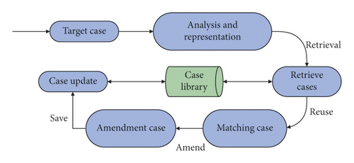
A typical problem-solving process based on case-based reasoning can be summarized into four steps: retrieve, reuse, revise, and retain, as shown in Figure 3.
2.5.2. Case Reasoning Scheme Design
In the nonstationary high-speed rail simulation channel model, based on the assumption of uncorrelated scattering and antenna stationarity, the statistical characteristics of the channel in different scenarios can be deduced, and the first tap of the channel model is emphatically analyzed, including the line-of-sight component and the single reflection component.
The setting of this utility function is the same as the expression of Shannon’s capacity, so the utility value of the signal-to-interference ratio between the user and the AP link is proportional to the maximum data rate available to the user.
- ③
Q-value table fusion is: the feature vector is obtained at the beginning of each time slot, and then the source case most similar to the target case is found from the case library. Changes in Q-value are made based on the similarity between cases. The Q-value fusion method of the target case and the matching case is:
We add the (s, a) combination pair that exists in the Q-value table of the target case and does not exist in the Q-values table of the matching case to the Q-value table of the matching case as the initial value of the Q-value table of the target case.
3. High-Speed Railway Communication Strategy Model Based on LIFI Technology
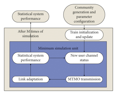
The entire simulation system adopts a modular design scheme. The simulation framework is shown in Figure 4, which mainly includes five functional modules, including cell model, user model, MIMO transmission, link adaptation, and system performance statistics.
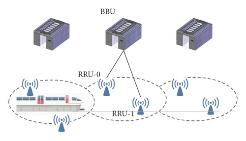
The cell of this simulation system adopts the networking mode of BBU + RRU. In order to facilitate the analysis, the cell model in the simulation in this chapter uses one RRU and one cell, as shown in Figure 5.
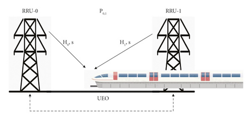
The train travels to the junction of the RRU, as shown in Figure 6(a). At this time, due to the influence of shadow fading, Doppler frequency offset, and multipath effect, the quality of the received signal is seriously degraded. At this time, if Type-0 CoMP is adopted, the serving RRU and the cooperative RRU of the user transmit the same data to the user at the same time, which can improve the quality of the signal received by the user. When two RRUs send data, the same precoding codebook is used, and the joint precoding codebook P is determined according to the channel conditions H0 and H1 of the user to different RRUs.
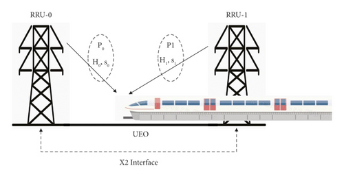
Under the Type-1 model, as shown in Figure 6, different precoding codebooks P0 and P1 are determined according to the channels H0 and H1 to adjacent RRUs. The cooperative RRUs use their respective precoding codebooks to send their respective data S0 and S1, and the data do not need to be synchronized at this time. The signal received by the user is the set of data sent by the two RRUs. The two cooperating RRUs share control signals through the backhaul channel, but do not need to maintain synchronization. This solution can be better applied to the inter-cell CoMP where synchronization is difficult to achieve.
In the current high-speed railway communication network, more and more communication devices are controlled by computers, and because in the computer system, the complexity of hardware failures is high, and the software also has a certain degree of potential failure, above fault. The definition of safety requires that in any fault condition, the general computer system can guarantee that the output is in a safe state, which will be difficult to achieve. Therefore, it is necessary to break through the traditional fault. Security concept, in order to find a way to solve the failure of the computer system. Safety issues, that is, to recognize faults from the perspective of relative safety and safe question.
The public network networking mode mainly means that communication can be performed on the base station site and base station equipment along the original high-speed line. Users on the high-speed railway line share this wireless network with other ordinary users along the line, and low-speed services along the high-speed railway line will not be affected by high-speed mobile sites. Moreover, high-speed routes do not use dedicated frequencies, and the entire network can use the same frequency configuration, reducing the number of frequency allocations. The schematic diagram of the public network networking mode is shown in Figure 7.
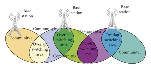
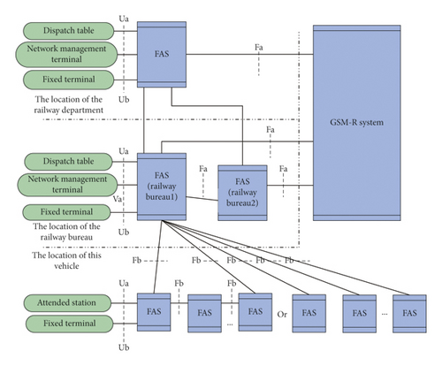
In the group call area design, it must be ensured that the base station area of the station covers more than 2000 meters on both sides of the station. Only in this way, the GSM-R group call area in the base station area of the station can be guaranteed. Figure 8 shows the networking mode of the dispatching communication system.
4. System Simulation
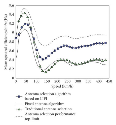
Figure 9 shows a simulation result of the variation of the average spectral efficiency with the speed of the traditional antenna selection algorithm, the weight preprocessing antenna selection algorithm, the fixed antenna algorithm, and the method based on the LIFI technology. A feasible way to improve the average spectral efficiency of the antenna selection algorithm is to adaptively switch between the traditional antenna selection algorithm and the algorithm proposed in this paper according to the speed. When the speed is less than 80 km/h, the traditional antenna selection algorithm is used, otherwise, the LIFI-based antenna selection algorithm is used.
On this basis, the effect of the high-speed railway communication strategy based on LIFI technology proposed in this paper is evaluated, and the evaluation results are obtained through the evaluation of multiple groups of experts, as shown in Table 1.
| No. | Evaluation results |
|---|---|
| 1 | 88.54 |
| 2 | 89.45 |
| 3 | 87.55 |
| 4 | 90.73 |
| 5 | 87.51 |
| 6 | 90.19 |
| 7 | 86.60 |
| 8 | 87.33 |
| 9 | 89.93 |
| 10 | 86.24 |
| 11 | 89.90 |
| 12 | 90.32 |
| 13 | 88.75 |
| 14 | 90.24 |
| 15 | 89.98 |
| 16 | 88.50 |
| 17 | 87.77 |
| 18 | 86.37 |
| 19 | 90.95 |
| 20 | 88.45 |
| 21 | 90.94 |
| 22 | 90.24 |
| 23 | 90.31 |
| 24 | 88.66 |
| 25 | 89.94 |
| 26 | 88.45 |
| 27 | 90.83 |
| 28 | 88.16 |
| 29 | 89.23 |
| 30 | 88.57 |
| 31 | 90.25 |
| 32 | 88.30 |
It can be seen from the above research that the high-speed rail communication strategy based on LIFI technology proposed in this paper can effectively improve the effect of high-speed rail communication.
5. Conclusion
High-speed rail wireless communication systems have their inherent advantages and disadvantages. For example, high moving speeds and channel feedback delays will make smart antenna-based beamforming techniques ineffective for transmission. In contrast, opportunistic beamforming technology based on non-smart antennas is more suitable for this scenario because it does not require real-time channel vector feedback and only requires channel SNR reporting. This paper combines LIFI technology to study the high-speed railway communication strategy and improves the high-speed railway communication effect through intelligent communication methods. Moreover, this paper studies the access point allocation problem in indoor LiFi/WiFi hybrid networks, fully considers the dynamic changes of network load, and introduces a dynamic load balancing algorithm that determines AP allocation in hybrid networks based on the data transmission rate as the switching threshold. The experimental study verifies that the high-speed rail communication strategy based on LIFI technology proposed in this paper can effectively improve the high-speed rail communication effect.
Conflicts of Interest
The authors declare no conflicts of interest.
Open Research
Data Availability
The labeled dataset used to support the findings of this study is available from the corresponding author upon request.


