Blind Crosstalk Correction for Color Fringe Projection Profilometry Combining the Sine and Cosine Phase-Shifting Patterns
Abstract
Color crosstalk is challenging for color fringe projection profilometry, which will cause color imbalance and phase-shift deviation, thus resulting in phase error. To address this challenge, this paper presents a blind crosstalk correction method for color phase-shifting fringe projection profilometry without crosstalk calibration. Three channels of the color fringe are firstly normalized to resolve color imbalance. The phase error induced by phase-shift deviation between three channels doubles the frequency of the color fringe. Therefore, the original cosine color fringe is shifted by quarter period to generate another sine color fringe to compensate the periodic phase error. Both simulations and experiments were carried out, and their results confirmed the effectiveness and accuracy of the proposed method.
1. Introduction
Fringe projection profilometry (FPP) based on triangulation principle is one of the most commonly used methods in optical three-dimensional (3D) shape measurement due to its low cost, fast speed, and high-resolution capabilities [1–6]. Normally, a FPP system contains a computer, a projector, and a camera. The projector and the camera are directed along different directions to the measured objects, all of which are controlled by the computer. Firstly, the fringe patterns should be designed and generated by the computer. Then, these patterns are projected onto the measured objects by the projector; at the same time, the deformed patterns are recorded by the camera. Finally, these captured images are transferred to the computer and analyzed by phase extraction algorithms to obtain the geometric information of the measured objects [7]. There are several phase extraction algorithms, including Fourier transform [8], wavelet transform [9], and phase-shifting profilometry (PSP) [10]. Among them, PSP is the most popular method, because it can achieve pixel-wise phase extraction, which can reconstruct the measured objects with abrupt changes more robustly. However, it generally requires more fringe patterns (normally at least three) than transform methods [11].
In order to overcome this problem, color phase-shifting technique has been developed [12–19]. Three phase-shifting patterns are assigned to red, green, and blue channels, respectively. Thus, only one color fringe pattern is required to reconstruct 3D shapes. However, the spectra of red, green, and blue channels are usually made to have some overlaps so that there would be no color-blind areas on the spectrum [20–22]. Thence, phase error will be introduced if conventional phase-shifting algorithms are employed directly. To suppress the phase error caused by color crosstalk, Huang et al. [23] proposed a method to compensate the coupling effects between channels. Since the degrees of overlaps are fixed, they projected pure red, green, and blue fringe patterns onto a white-painted flat board to calculate the degrees of coupling effects between three channels and then compensated it. This method has been explored when different numbers of fringes are projected on each channel by Zhang [24]. On the other hand, Wan et al. [25] presented an active phase error suppression method based on hue precorrection. The hue is precorrected to be linear by measuring the function of the combined effect and modifying the computer-generated hue according to the source-distorted relationship. Then, the new modified color fringe pattern can be generated for measuring objects. However, all these techniques need preprocessing before measurement, which makes it inconvenient to use. Hu et al. [26] proposed an algorithm for estimating the color remixing matrix based on the color fringe patterns captured from the reference plane or the surface of objects. Ma et al. [27] proposed a blind phase error suppression approach based on isotropic n-dimensional fringe pattern normalization [28] and carrier squeezing interferometry [29]. Wu et al. [30] proposed a point-to-point compensation method for color coupling and imbalance. The proposed method achieves point-to-point compensation based on the correspondence between camera pixels and projector pixels. Recently, Wang et al. [31] found the phase error introduced by crosstalk is approximately twice the frequency of color fringe. Therefore, Hilbert transform was applied on the color fringe to compensate the phase error. However, due to the fact that Hilbert transform belongs to frequency domain methods, this approach cannot handle the measured objects that contain discontinuities or separations well.
In this paper, we present a blind crosstalk correction method for color phase-shifting fringe projection profilometry. Due to the fact that phase error introduced by color crosstalk is twice the frequency of color fringe, the other color fringe with phase-shift is used to compensate the phase error. In addition, the fringe normalization was also designed to resolve the color imbalance problem. We describe the principle of this method in Section 2. Simulations and experiments are illustrated in Sections 3 and 4, respectively. Finally, Section 5 summarizes this work.
2. Principle
2.1. Color Phase-Shifting Fringe
2.2. Color Crosstalk Model
2.3. Phase Error Analysis
This indicates that the phase error approximately doubles the frequency of the color fringe.
2.4. Phase Error Compensation
2.5. Fringe Normalization
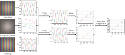
As shown in Figure 1, the framework of the proposed method contains three steps. Firstly, a background pattern is used to remove color imbalance in different channels of cosine and sine fringes. Then, two phase maps with phase errors caused by phase-shift deviation are extracted, respectively. Finally, the phase error caused by phase-shift deviation is compensated by averaging two phase maps.
3. Simulations
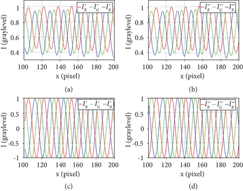
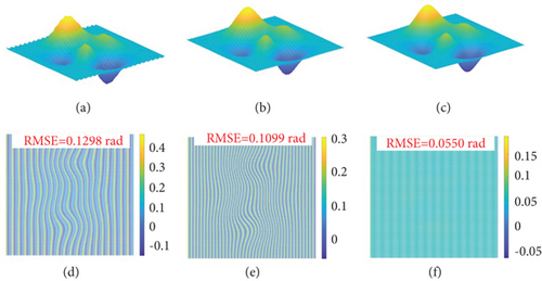
Figures 2(a) and 2(b) plot the 300th cross sections of cosine and sine fringes before fringe normalization, respectively. Obviously, the problem of color imbalance was existing in different channels. Then, the color imbalance problem was eliminated by fringe normalization, and the fringes after fringe normalization are shown in Figures 2(c) and 2(d). Figure 3(a) shows the 3D shape obtained before fringe normalization; periodic errors can be seen clearly. As shown in Figure 3(b), these errors were decreased after fringe normalization, but the errors caused by phase-shift deviation were still existing. Figure 3(c) shows the 3D shape retrieved after phase error compensation. Apparently, periodic errors were effectively suppressed by the proposed method. The reconstructed surface is very smooth, with almost no visible errors. In addition, their corresponding root mean square errors (RMSE) are shown in Figures 3(d)–3(f). Before fringe normalization, the RMSE in Figure 3(d) is 0.1298 rad. Figure 3(e) shows that the RMSE was reduced to 0.1099 rad after fringe normalization. And the RMSE, as shown in Figure 3(f), was reduced to 0.0550 rad after phase error compensation. This simulation illustrates the effectiveness of the proposed method.
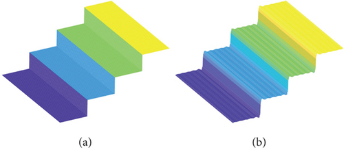
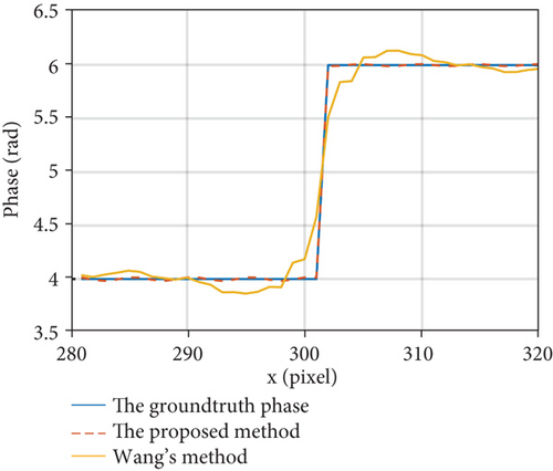
To compare the proposed method with Wang’s method [31] which uses frequency domain method, a staircase with four steps was simulated. The 3D shapes reconstructed by the proposed method and Wang’s method are shown in Figures 4(a) and 4(b), respectively. Obviously, Wang’s method performed worse than the proposed method because it uses frequency domain method, which is not suitable for processing objects with abrupt surfaces. Figure 5 illustrates a part of the 300th cross section, which contains the abrupt change between the third and fourth steps. The third and fourth stairs are marked in green and yellow in Figure 4, respectively. The distortion of the abrupt change retrieved by Wang’s method is more serious than the proposed method. This simulation demonstrates that the proposed method can handle objects with abrupt surfaces well.
4. Experiments
In this paper, we choose Th = 18 pixels. Thus, Tm = NTh = 144 pixels and Tl = N2Th = 1152 pixels.
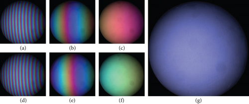
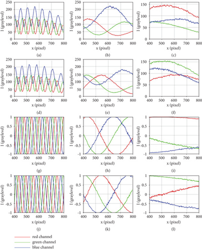
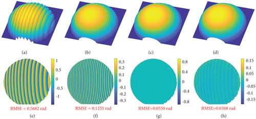
In the first experiment, a ball was measured. Total seven patterns were projected onto the ball and captured by the camera, as shown in Figure 6. Figures 6(a)–6(c) show the deformed cosine fringe patterns with periods of 18, 144, and 1152 pixels, respectively. Their corresponding sine fringe patterns are shown in Figures 6(d)–6(f). Figure 6(g) shows the background pattern that is used for fringe normalization. Before phase error compensation, we need to normalize these fringes to address the color imbalance problem. Figure 7 shows the 500th cross sections of six color patterns. Obviously, the imbalance problem existing in Figures 7(a)–7(f) was effectively resolved after fringe normalization, and the normalized fringes are shown in Figures 7(g)–7(l). Afterwards, the reconstructed 3D shapes are shown in Figure 8. Among them, Figure 8(a) shows the 3D shape reconstruction before fringe normalization; periodic phase errors are clearly visible. Then, the fringe normalization method was employed, and the 3D shape retrieved after fringe normalization is shown in Figure 8(b). The phase errors caused by color imbalance were suppressed, but the phase errors caused by phase-shift deviation were still existing. Thus, Wang’s [31] and the proposed methods were both applied to compensate these errors, and the reconstructions obtained are shown in Figures 8(c) and 8(d), respectively. Visually, both Wang’s and the proposed methods effectively suppressed the phase errors in the center of the ball. However, the frequency domain method used by Wang caused large errors in the edge areas, especially the upper edge of the ball. In order to quantify errors, we also used 18-step phase-shifting method [8] to measure this ball and compared the measurement result with the above four processing results. The corresponding deviation maps are shown in Figures 8(e)–8(h). The RMSE of the reconstruction before fringe normalization is 0.5682 rad, and it is reduced to 0.1255 rad after fringe normalization. As shown in Figures 8(g) and 8(h), after phase error compensation, the RMSEs of Wang’s and the proposed methods are 0.0550 and 0.0368 rad, respectively. And the maximum phase error of Wang’s method reaches 0.8 rad in edge areas which is 5.3 times that of the proposed method. In addition, Figure 9 plots the 800th cross section of the center of the ball. This experiment shows that both Wang’s method and the proposed method are reliable in processing smooth object, but the proposed method handles edge areas better than Wang’s method.
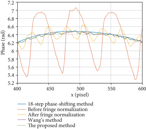
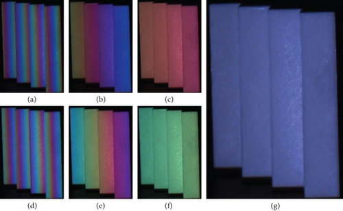
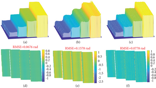
In order to further compare the proposed method with Wang’s method in dealing with object with abrupt surface, a staircase with four steps was measured. All captured patterns are shown in Figure 10. Similarly, the 18-step phase-shifting method was used as a reference. Figures 11(a)–11(c) show the 3D reconstructions recovered by 18-step phase-shifting, Wang’s, and the proposed methods, respectively. Visually, the 18-step phase-shifting method performed best while Wang’s method worked the worst. Due to the application of frequency domain method, the abrupt changes between steps were smoothed, resulting in incorrect measurement. The abrupt changes between steps reconstructed by the proposed method are obviously better than Wang’s method. Furthermore, we performed plane fitting on each step of the reconstruction retrieved by 18-step phase-shifting method. Figures 11(d)–11(f) show the deviation maps between the three reconstructions and the fitting results. Markedly, the accuracy of the proposed method is similar to that of the 18-step phase-shifting method, with only a difference of 0.01 rad. However, the RMSE of Wang’s method is approximately twice that of the proposed method. Figure 12 plots the 800th cross section of the staircase. The proposed method almost coincides with 18-step phase-shifting method, while Wang’s method performs poorly. This experiment confirms that the proposed method is more robust and accurate than Wang’s method in dealing with object with abrupt surfaces.

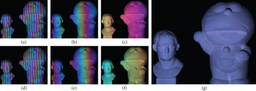
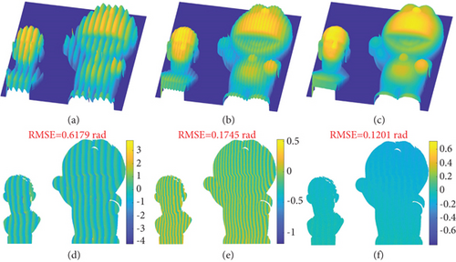
Two isolated sculptures were also measured to verify the actual measurement effect of the proposed method. All captured images are shown in Figure 13. Figure 14 shows the reconstructed 3D shapes, and the reconstruction in Figure 14(c) is significantly better than that in Figures 14(a) and 14(b). Figures 14(d)–14(f) show their corresponding deviation maps. Compared with the result before fringe normalization, the proposed method significantly improved the measurement accuracy, and the RMSE of the proposed method is only one-fifth of that before fringe normalization. This experiment demonstrates that the proposed method has sufficient robustness and accuracy in the actual measurement.
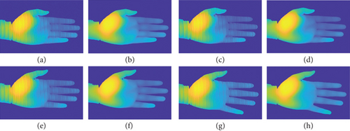
To further validate the dynamic measurement performance of the proposed method, one moving hand was measured. Figures 15(a)–15(d) show the 3D shapes reconstructed without color crosstalk compensation, and phase errors can be seen clearly. In contrast, the corresponding frames processed by the proposed method have no obvious errors, as shown in Figures 15(e)–15(h). This experimental result further confirms that the proposed method can effectively compensate the phase errors and improve measurement accuracy in dynamic measurement.
5. Conclusion
This paper presents an effective color crosstalk correction method for color FPP without crosstalk calibration. Due to the fact that phase error induced by color crosstalk is approximately twice the frequency of color fringe, the other sine color fringe was used to compensate the phase error. Both simulations and experiments confirmed the effectiveness of the proposed method. Experimental data shows that the proposed method has the ability to deal with objects with abrupt surfaces, and phase error caused by color crosstalk can be reduced to one-fifth after applying the proposed method.
Conflicts of Interest
The authors declare that there is no conflict of interest regarding the publication of this paper.
Open Research
Data Availability
The data used to support the findings of this study are available from the corresponding author upon request.


