Smart Sensor Network Optimization and Line Defect Identification Based on UAV Transmission Inspection under 5G Technology
Abstract
Transmission line is a key link in the transmission line, as the main equipment in the grid are located in the field; in the long-term harsh environmental conditions, the line is very easy to appear broken strands, broken, and other defects, which need to be regularly monitored and maintained. The traditional manual line inspection operation is not only harsh, labor-intensive, inefficient, and low precision but also has a great impact on the personal safety of the operators due to the complicated operating conditions. This project mainly focuses on 5G, intelligent sensor network technology, and the application of UAVs in high-voltage line inspection, detection, and maintenance. The developed inspection UAVs can effectively improve the efficiency of line inspection and quickly discover fault points, which brings convenience to the construction of power systems. In the 5G environment, the use of UAV transmission inspection technology for line fault identification can overcome the shortcomings of manual faults, but also timely and comprehensive fault detection, and improve the effectiveness and standardization of monitoring work.
1. Introduction
Electricity is an important energy artery in China, its main carrying capacity is the transmission network, and maintaining the normal operation of the power grid plays a vital role in the stable development of the national economy [1]. China has the second largest transmission line in the world, but due to the high terrain in China, transmission lines often have to cross mountains, freezing, high altitude, and geological disasters [2]. It is relatively easy to quickly establish such a transmission network, but long-term maintenance is labor-intensive and capital-intensive [3].
At present, China’s research on the use of manned helicopters for transmission line inspection is still in its infancy, and some concrete experience and results have been achieved. Although manned helicopters patrolling transmission lines can significantly improve the efficiency of patrol work, conventional manned fixed-wing and manned helicopters patrolling transmission lines will have certain defects due to the strict domestic aviation control system [4–7]. It is difficult to ensure regular patrols because pilot training, application for routes, adjustment, shutdown, and maintenance are very time and energy consuming and expensive to operate, subject to weather and geographical conditions, as well as sudden bad weather, which poses a great threat to passengers’ lives. In the high-voltage line patrol of UAVs, the cost includes the safety of flight routes, air control, weather during the flight, flight route selection, maintenance and contact of use, flight safety and operation [8].
Under different terrain conditions, the use of UAVs for inspection of high-voltage transmission lines can effectively reduce the workload of operators and effectively reduce the operation and inspection costs of transmission lines. Since the safety of UAVs is not as good as manual piloting under harsh climatic conditions, they need to be evaluated for causing greater economic losses. Small UAVs are lightweight, flexible, and can carry advanced aerial photography equipment, which is a better auxiliary means for transmission line monitoring. The use of drones monitors high-voltage transmission lines [9], you can obtain the required images in the shortest possible time, while real-time data transmission and decision-making, in the same working hours, you can achieve ten times the workload of manpower, the operational efficiency of drones is higher than that of unmanned aircraft, the cost is lower, the requirements of the environment is also lower, and you can perform more complex and more dangerous power equipment patrol. (2) Has a higher of safety. The biggest feature of the UAV is that it does not need a pilot and will not be life-threatening, so it is more suitable for performing high-intensity, high-risk tasks. (3) Suitable for field work. In the design of UAVs, the size of the aircraft is reduced [10], the size of the fuselage is reduced, the size of the aircraft itself is reduced, the weight of the aircraft is reduced, and the flight speed and survival rate of the aircraft are increased because the size of the pilot and the safety of the passengers are not considered. Compared to manned aircraft of equal weight, UAVs have a smaller size and greater flexibility to adapt to more demanding environments. Micro-UAVs can move freely and can be carried around, even in ordinary family cars, and because UAVs do not require a fixed apron, they can be put into combat at any time. (4) Low use and maintenance costs. In addition to batteries and other consumables, the normal service life of drones exceeds 10 years, and maintenance costs are very low without considering factors such as aircraft crashes. Compared to expensive rented manned helicopters, which require a lot of preparation and too many uncontrollable factors and are susceptible to the effects of climate to be used properly, so after the purchase of the drone, the drone will belong entirely to itself, at what time and where it is used.
In transmission line inspection, the use of UAVs for inspection can effectively improve the quality of line inspection work and improve the scientific nature of monitoring, thus achieving better social and economic benefits [11]. UAV inspection is a fast, efficient, and promising new inspection method, which is the development direction of power system monitoring. In the past decades, the monitoring technology of unmanned aircraft on high-voltage transmission lines has been explored, studied, and practiced at home and abroad, but there is still a large gap from fully satisfying the monitoring, inspection, and maintenance work of high-voltage transmission lines.
With the improvement of the reliability of the power system and the performance of unmanned aircraft, the advantages of unmanned aircraft in the monitoring of transmission lines will become increasingly prominent.
The subject for 5G technology and intelligent sensor network technology, the use of unmanned aerial vehicles for high-voltage transmission line inspection, detection, and maintenance aspects of in-depth research, and the development of inspection of unmanned aerial vehicles can effectively improve the efficiency of transmission line inspection, faster detection of fault points, and greatly improve the efficiency of the charged operation at the same time can provide a certain degree of convenience for the construction of transmission lines [12].
2. Introduction to Related Theories
2.1. 5G Technology Theory
5G, as a new type of mobile communication network, should not only solve the human-to-human communication but also provide a variety of functions such as augmented reality, virtual reality, and ultrahigh definition (3D). It should solve the problem of human-to-thing and thing-to-thing communication and meet the needs of mobile medical, vehicle networking, smart home, industrial control [13], environmental monitoring, and other IoT applications. 5G will gradually penetrate into all fields of economy and society and become 5G will gradually penetrate into all areas of the economy and society and become an important infrastructure for the digitization, networking, and intelligence of the economy and society.
5G systems provide a new service architecture for achieving flexible deployment and multiple service environments. 5G full service, with modular network functions, can be invoked and functionally reorganized at any time; the adoption of service descriptions facilitates the opening of enterprise capabilities, which is conducive to the introduction of IT development momentum and giving full play to its potential. 5G supports flexible deployment based on NFV/SDN and decouples software, hardware, and control forwarding separately; the adoption of common data centers makes network functions more flexible and resource allocation more efficient; and cloud computing platforms support edge computing that can reach the edge of the network and provide flexible application and boundary translation. Network slicing is the customization of specific functions and features to make it a logical network with different functions and services for different service targets [14].
5G is a representative of the new generation of information technology, and its deep integration with industry provides a new way for the development of digitalization, networking, and intelligence of industry [15]. 5G technology is applied to industrial applications covering 16 industries such as R&D, design, manufacturing, operation management, and product service, including AR/VR R&D experiment collaboration, AR/VR collaborative design, remote control, AR/AR assisted assembly, machine vision, AGV logistics, automatic driving, ultrahigh definition video, equipment perception, material information collection, environmental information collection, AR product demand introduction, remote after-sales, product status monitoring, equipment predictive maintenance, and AR/VR remote training. At present, machine vision, AGV logistics, ultrahigh-definition video, and other technologies have been widely used to achieve the purpose of “machine for human,” greatly reducing labor costs, improving the accuracy of detection, and improving production efficiency. In the future, remote control, predictive maintenance of equipment, and other applications can be realized.
2.2. Intelligent Sensor Network Theory
A smart sensor network is a network consisting of a large number of stationary or mobile sensors for monitoring target information in the area covered by the network, processing, and transmitting it. Therefore, sensors, sensing objects, and users constitute the three main factors of a sensor network. The communication path between the three nodes consists of three different wireless networks that collaborate to sense, collect, process, and transmit, thus achieving the basic functions of the sensing network [16].
- (1)
Self-Organization. In the intelligent sensing network, sensor nodes are generally located in the field with poor environmental conditions, and aircraft is generally used for mass deployment, which cannot determine the location in advance. This requires automatic configuration and management of multihop wireless networks in the wireless network. Since the nodes in the network have a strong randomness, nodes can suddenly die under the influence of signals, energy consumption, obstacles, and other factors, while new nodes enter the network, which requires the WRT to have the ability to self-organize
- (2)
Multihop. Because the communication distance between single nodes is usually tens to hundreds of meters, the transmission of information from the source to the target node must go through intermediate nodes, which requires conventional network nodes to have multihop routing capabilities [17]
- (3)
Dynamic network structure
- (4)
Focus on data
In the Internet, each device has an IP and identifies information with an address. In wireless sensor networks, there is no IP address in each network, each network has an ID, the network IDs in the network are not unique, depending on the particular application, and multiple nodes in the network with the same ID are differentiated. After receiving information about the particular event described, the network reports it to the user. If the Internet is an address-based network, the wireless sensor network is the information network.
2.3. UAV Inspection Theory
UAV is an unmanned aircraft operated by wireless remote control equipment or its own program; it was first used for military purposes; the United States, the United Kingdom, Canada, and other countries are developing tactical drones; in 1917, the United Kingdom has also conducted the first test. Military drones usually carry imaging, radar, radio, and other equipment, such as the U.S. Global Hawk, Predator, Israeli Pioneer UAV, the French “kestrel (Crecerelle),” the British “Phoenix (Phoenix),” and “dark sword” [18].
UAV inspection process includes (1) preinspection preparation: complete the task center’s inspection of transmission lines, check the equipment needed for inspection, assemble and debug the test drone, install the camera, assemble the arm, install the battery, check whether the UAV is properly connected, whether the body structure is solid, whether the wireless map transmission is normal, whether the battery voltage is sufficient, debug the UAV to ensure that the gimbal is stable, the body stable, the body is balanced, the camera is clear, develop line inspection routes and flight plans, and the ground control system can work normally and can receive information from the UAV, including attitude and voltage. Develop flight plan and flight route. (2) Workflow of the UAV: execute the inspection task of the mission center, develop the plan of the inspection route, develop flight plan, test the operation of the UAV, ensure the working performance of the UAV, and take aerial photos at the predetermined location. (3) After completing the inspection, the UAV returns to the control center and stores the data.
3. Application Method Design
3.1. Application Architecture
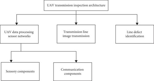
- (1)
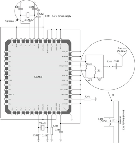
Sensing component for sensing, acquiring information from the outside world, and converting it into a digital signal
- (2)
The communication component responsible for communicating with other sensors or users
- (3)
Transmission line image transmission, which is mainly for screening and transmitting the image information transmitted by the node
- (4)
The line fault identification refers to the identification of defects in the images sent by the image processor and the processing of the images using internal integrated algorithms, before feeding the data back to the user
3.2. Intelligent Sensor Network Optimization Design
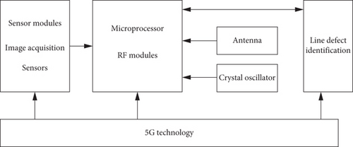
In the process of unmanned vehicle line fault, it needs to be completed with the help of multiple sensors, while the intelligent wireless sensor network designed in this topic is completed by the sensors to monitor the transmission line and transmit the collected data to the convergence node through wireless communication and analyze it [20]. In this paper, a line fault identification system based on 5G technology is designed. It uses artificial 5G technology to achieve the optimal design of an intelligent sensor network, mainly including the speed of data acquisition, the speed of image analysis, and the accuracy of line defect identification. The basic structure of the optimized design of wireless sensor nodes applicable to UAV transmission patrol designed in this paper is shown in Figure 3.
3.3. Image Graying
In order to better identify the transmission line, the transmission line must be highlighted as much as possible, but in practice Figure 3, not only the transmission line is more prominent, but also the house in the background is particularly prominent. In addition, in the overall processing of the image, we found that different methods were used to process grayscale images, but the actual helicopter aerial images were in color. To ensure a good input format for future functions, the acquired color aerial photography is first processed in grayscale in the image processing [21].
Where the original image is represented by the parameter src, the dst parameter represents the resulting grayscale profile, and the parameter code input RGB2GRAY represents RGB space to GRAY.
Using this function, the helicopter aerial image is converted from a color image to a gray image, which is visible after the grayscale processing, and the contour of the wire becomes larger for subsequent recovery and can be used as appropriate input information for subsequent functions.
3.4. UAV Flight Management Workbench
The flight management platform of UAV mainly includes the management of real-time image and the management of flight. Real-time image management means receiving the image of the UAV during the patrol and analyzing and processing it [22], so as to display the position, status, operation status, operation parameters, and power voltage of the UAV in real time. When there is an error in the operating status of the UAV, the pilot should be notified immediately to make adjustments to prevent accidents. The flight management of the UAV is to plan the patrol route of the UAV according to the line and the environment around the line, to formulate the patrol route, and to let the UAV patrol according to the established route. The flight status of the UAV is detected and adjusted to prevent unnecessary losses; the UAV is patrolled in accordance with the needs of the patrol task and the completion of the UAV operation, and the whole line patrol is completed.
3.5. Line Defect Identification
Fault identification platform is a key link to realize transmission line fault identification and a key link in the whole ground monitoring system. Through extraction, preprocessing, edge detection, segmentation, and other methods, defects of conductors and insulators are detected; if defects appear, alarm prompts for processing and records the inspected line, the specific content of defects, the time of appearance, and defects for later inspection and analysis.
The drone completes the monitoring of the transmission line and transmits the transmitted line images to the ground monitoring system with high-definition pictures and uses image defect recognition technology for fault identification and processing. The process of image defect recognition includes: image reading, preprocessing, foreground extraction, target identification, and processing. The recognition of image defects mainly includes the intelligent recognition of insulator lines and wires, while the recognition of insulator defects is transformed into HSV space and then detected in H-space. Based on this, the H-space is binarized using appropriate thresholds to obtain the connection area of each isolator string connection and circle it within a square. Finally, the ratio between the nonzero value of each block and the block area is calculated, and if this ratio is lower than a specific empirical value, it indicates the presence of defects in this area. Identification of loose strands and broken strands defects of the wire: the first step was also to binarize the image to eliminate the influence of the complex environment outside the wire on the image. Then, the image was extended and eroded to eliminate isolated noise from the noise. The method was obtained by fitting a straight line to the points in the figure. Finally, the fitted midline is used as a benchmark for ANOVA, and if there are loose or broken strands, the variance is large, and an empirical threshold can be set to determine whether the wire is loose or broken.
4. Application Experiment Analysis
4.1. Experimental Commissioning
Prior to the test, it was necessary to power up the aircraft and signal the various sensors (see Table 1), as well as the direction of rotation of the thrusters, according to the aircraft’s circuit design drawings. Also, it is ensured that all parts of the aircraft are properly installed, and all electronic equipment is powered up, and then the test can begin.
| Aircraft power-on test | The first test | Second test | The third test | The fourth test | Passing rate |
|---|---|---|---|---|---|
| Drone | Normal | Normal | Normal | Normal | 100% |
| Image acquisition sensor | Normal | Normal | Normal | Normal | 100% |
| Image transmission components | Normal | Normal | Normal | Normal | 100% |
| Image recognition system | Normal | Normal | Normal | Normal | 100% |
| Other sensors | Normal | Normal | Normal | Normal | 100% |
4.2. Data Acquisition
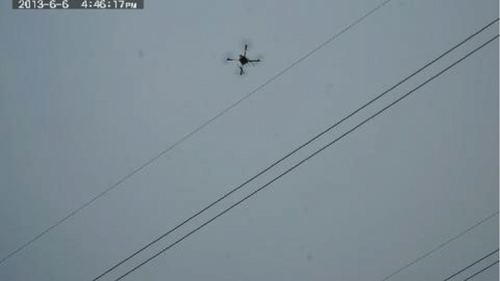
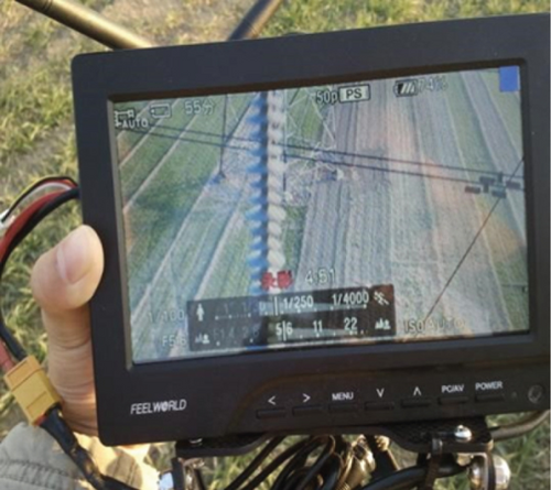
This time, the data source is mainly through the UAV for outdoor multi-image acquisition, then the image data transmission sensor for transmission, and finally complete the identification of line defects. As shown in Figure 4, the flight of the UAV in the work is predetermined area, and Figure 5 is the unmanned image acquisition feedback.
4.3. Application Experiment
After inspecting the transmission line, the drone uses wireless map transmission to transmit the monitored data to the ground monitoring site for fault identification. The ground observation system receives, stores, analyzes, and processes the real-time image data operated by the UAV on the line. Once a fault is detected, the fault identification result is displayed, and a timely alert is issued. Because the parameters are different in each environment, they have to be reset for each operation.
- (1)
Start Cygwin in Windows
- (2)
Start the process of providing web services
- (3)
Start AVR Studio
- (4)
Click the “…” button in the Flash project, select the Hex file and click “Program” to download the selected Hex file to the node
- (5)
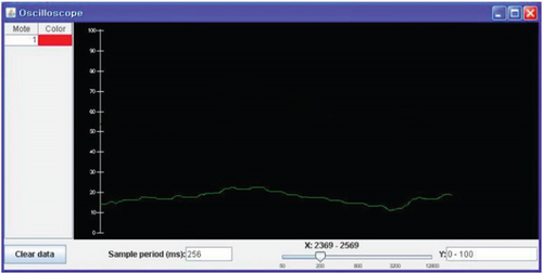
Start the Java oscilloscope application
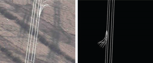
In line fault detection, the image is first grayed and binarized to eliminate the influence of the complex environment outside the conductor on the image. The binarized image obtained by preprocessing and edge detection of transmission lines contains discontinuous points and noise, so the Hough transform must be used for linear extraction and its suppression. The Hough transform uses the linear detection method to remove the strip interference to the wire and to truncate a section between two lines at the maximum intercept and the minimum intercept and to remove the connection area beyond the two lines. The extraction effect of this application system on transmission lines is shown in Figure 7.
5. Conclusion
Images are the main way for humans to get information. With better processing algorithms, faster processing speed, and clearer image processing technology, image recognition and processing technology is getting more and more applications. In the past, in transmission line inspection, visual recognition was usually done by eyes, but it was difficult to establish a complete discriminatory system because there were certain limitations, and some tiny hidden dangers could not be detected by naked eyes, especially in the fatigue state of inspectors, which could easily produce errors. In the 5G environment, the use of UAV transmission inspection technology for line fault identification can overcome the shortcomings of manual faults, but also timely and comprehensive fault detection, and improve the effectiveness and standardization of monitoring work. The subject for 5G technology and intelligent sensor network technology, the use of unmanned aerial vehicles for high-voltage transmission line inspection, detection, and maintenance aspects of in-depth research, and the development of inspection of unmanned aerial vehicles can effectively improve the efficiency of transmission line inspection, faster detection of fault points and greatly improve the efficiency of the charged operation at the same time can provide a certain degree of convenience for the construction of transmission lines.
Conflicts of Interest
The authors declared that they have no conflicts of interest regarding this work.
Acknowledgments
This work was supported by the project is funded by the Science and Technology Project of China Southern Power Grid Corporation (project number: 030600KK51200001).
Open Research
Data Availability
The dataset used in this paper are available from the corresponding author upon request.


