Volume 2022, Issue 1 5975816
Research Article
Open Access

Enhancing Interpretability of Data-Driven Fault Detection and Diagnosis Methodology with Maintainability Rules in Smart Building Management

Michael Yit Lin Chew

Michael Yit Lin Chew

Department of the Built Environment, National University of Singapore, Singapore 117566, nus.edu.sg

Search for more papers by this author
Ke Yan

Corresponding Author

Ke Yan

Department of the Built Environment, National University of Singapore, Singapore 117566, nus.edu.sg

Search for more papers by this author
First published: 04 January 2022
Citations: 20
Academic Editor: Haidong Shao

Abstract

Data-driven fault detection and diagnosis (FDD) methods, referring to the newer generation of artificial intelligence (AI) empowered classification methods, such as data science analysis, big data, Internet of things (IoT), industry 4.0, etc., become increasingly important for facility management in the smart building design and smart city construction. While data-driven FDD methods nowadays outperform the majority of traditional FDD approaches, such as the physically based models and mathematically based models, in terms of both efficiency and accuracy, the interpretability of those methods does not grow significantly. Instead, according to the literature survey, the interpretability of the data-driven FDD methods becomes the main concern and creates barriers for those methods to be adopted in real-world industrial applications. In this study, we reviewed the existing data-driven FDD approaches for building mechanical & electrical engineering (M&E) services faults and discussed the interpretability of the modern data-driven FDD methods. Two data-driven FDD strategies integrating the expert reasoning of the faults were proposed. Lists of expert rules, knowledge of maintainability, international/local standards were concluded for various M&E services, including heating, ventilation air-conditioning (HVAC), plumbing, fire safety, electrical and elevator systems based on surveys of 110 buildings in Singapore. The surveyed results significantly enhance the interpretability of data-driven FDD methods for M&E services, potentially enhance the FDD performance in terms of accuracy and promote the data-driven FDD approaches to real-world facility management practices.

1. Introduction

1.1. Motivation

Aligning with the fast development of artificial intelligence (AI) technology, data-driven fault detection and diagnosis (FDD) plays an essential role in modern smart building maintenance and management systems [1]. However, while the data-driven FDD models are often viewed as black-box models, the interpretability of FDD models hinders the methods to be widely applied to real-world applications [2, 3]. Expert rules and standards are helpful for data-driven FDD methods to be adapted to real-world scenarios. The expert rules and standards not only increase the interpretability level of the data-driven FDD methods but also improve the FDD performance in terms of diagnosis accuracy rates. According to our literature survey, the relevant expert knowledge is considered as a research gap in the field and is highly demanded to detect and diagnose possible faults in building equipment and services [46]. In this study, we are interested to concretize the expert knowledge, using maintainability rules and standards for FDD, both regionally and globally, of different building mechanical & electrical engineering (M&E) services, including HVAC systems, plumbing & sanitary, fire safety, electrical and elevators & escalators systems, and their critical components.

1.2. Background

Building fault detection and diagnosis (FDD) methods automatically recognize potential and existing building facility faults based on existing standards, expert knowledge and sensor information, which are important techniques ensuring the safety, efficiency and quality services of building infrastructure and development [7, 8]. According to the different approaches replying to different types of evident information, FDD methods are categorized into data-driven FDD, physical model based FDD and mathematical model based FDD methods [9]. Data-driven FDD builds computational models based on historical sensor data, while different types of building faults are recognized as classes [10]. A physical model based FDD understands the whole building system using physics-based models and usually requires a significant amount of prior knowledge for faults identifications [11, 12]. A mathematical model based FDD methods also requires prior physics knowledge to define a rule space for an inferencing method searching for the corresponding faults [13, 14].

Data-driven fault detection and diagnosis methods represent the next-generation facility management and maintenance techniques adopting modern AI techniques, such as sensor networks [15, 16], data analytics [17], big data [18, 19], machine learning (ML) [20, 21], cybernetic intelligence (CI) [22, 23] and Internet of things (IoT) [24, 25] and etc. For different building infrastructures, such as heating, ventilation air-conditioning (HVAC), plumbing, fire safety, electrical and elevator systems. In the era of big data, smart building and smart city, data-driven FDD usually serves as one of the most important applications utilizing big data and one of the hottest research topics in the fields of smart city and industry 4.0 [2628].

Compared with traditional physical model based and mathematical model based methods, data-driven FDD methods are usually more efficient, robust and accurate in detecting and diagnosing various building faults, while the machine learning (ML) techniques, such as the neural networks, are constructed for predictive analysis. The ML techniques are generally much more efficient and effective than traditional PM-FDD, MM-FDD and manual classification methods. For example, for HVAC FDD, the existing works showed FDD accuracy rates over 99% for typical chiller faults and 93% for air handling unit (AHU) faults [2932]. Traditional approaches, such as the sensitivity test, can only achieve accuracy rates close to 83% for chiller faults and around 80% for AHU faults [3337]. The 10% to 15% improvement on different FDD approaches saves the energy wasted in buildings significantly, enhances the overall building performance and maintains a sustainable environment for building infrastructure maintenance.

However, the interpretability of the data-driven FDD method has always been the problem for data-driven FDD methods and hinders the data-driven FDD techniques to be widely adopted in real-world applications. While the prediction accuracy and efficiency of the data-driven FDD methods improved significantly in recent years, the internal structures of the AI approaches become more complex, resulting in more challenges for model interpretation [3841]. The data-driven FDD models were also tentatively called black-box models in many existing publications [4244], which we believe is not accurate. Many data-driven FDD models are indeed interpretable. For example, Yan et al. [45] presented a decision tree model for FDD of air handling units (AHUs). The decision tree structure is interpretable with if-else rules. However, the if-else rules were not easily recognizable for experts deriving standards for AHU maintenance.

It is evident that the expert knowledge, experience, rules, ISO standards and maintenance guidelines are valuable information and can deeply influence the performance of data-driven FDD methods. Zhao et al. [46] demonstrated that the additional expert knowledge inputs can greatly enhance a Bayesian belief network (BBN) data-driven FDD model’s performance by increasing the FDD accuracy for various chiller faults. Li et al. [47] improved [46] by integrated expert knowledge into a diagnostic Bayesian network (DBN) for AHU fault FDD. The reasonings of the AHU FDD were plotted by local casual graphs. The main shortcoming of the works [46, 47] is that the expert knowledge inputs were generally generated based on the authors’ hypotheses.

1.3. Approach

In this study, we reviewed the recent publications on data-driven FDD for building mechanical & electrical engineering (M&E) services, including HVAC, plumbing, fire safety, electrical and elevator systems. Different M&E faults were surveyed over 110 buildings in Singapore, including commercial, hotels, industrial, institutional, clinical and residential buildings, for all three stages of infrastructure management life-cycles, in all design, construction and management stages. The expert knowledge of M&E FDD is converted into maintainability rules and international/local standards in Singapore. It is evident that the conveyed maintainability rules greatly enhance the interpretability of the data-driven FDD approach and potentially improve the diagnosis accuracy.

We propose two data-driven FDD methods integrating the maintainability rules for general facility management in buildings, particularly focusing on FDD. The two specific data-driven FDD methods integrating maintainability rules are 1. data-driven expert rules for decision making in smart building facility FDD; and 2. maintainability rules as inputs for data-driven FDD systems. The actual implementations of the two proposed approaches were omitted, while there were existing implementations such as [46, 47]. The main aim of this study is to specify the expert knowledge pool of M&E FDD using maintainability rules shown in Section 4. The specification greatly enhances the interpretability of the existing M&E FDD methods.

1.4. Contributions

The current work involves the following contributions to the state-of-art.
  • (i)

    Extending the existing data-driven FDD from HVAC systems to the infrastructure of the whole building. The majority of the existing work of data-driven FDD integrating expert knowledge, e.g., maintainability rules, focuses on HVAC FDD. In this study, we extend the above-mentioned data-driven FDD framework to the whole building system. The targeted facilities include almost all M&E services for smart building design

  • (ii)

    Identifying expert rules and standards for various M&E faults in buildings. A total of 110 buildings in Singapore, including commercial, hotels, industrial, institutional, clinical and residential buildings were surveyed, over all three stages of infrastructure management life-cycles, in all design, construction and management stages, collecting necessary FDD information based on experts’ knowledge and international/local standards in Singapore. In this way, typical faults for the major M&E equipment are surveyed with detailed experts’ rules and standards stated in tables. This main contribution impacts the literature for data-driven FDD approaches targeting building M&E services significantly

  • (iii)

    Enhancing the interpretability of the existing data-driven FDD methods for building infrastructure faults. The interpretability of the data-driven FDD methods has been a bottleneck problem for a long time. The surveyed expert rules and standards bridge the gap between theoretical FDD strategy and real-world practices. The interpretability enhancement greatly improves the practicality of the data-driven methods in Industry 4.0 [48] and Construction 4.0 [49].

  • (iv)

    Potentially improving the diagnosis accuracy of the existing data-driven FDD methods for building infrastructure faults. According to the literature study, such as the works of [46, 47], expert knowledge, e.g., the maintainability rules enhance the FDD performance significantly in terms of accuracy. The diagnosis accuracy improvements are justified by various publications [46, 47, 5052].

2. Literature Review for Interpretability Study of the Existing M&E Services FDD Methods

Intelligent facilities management is one of the important topics for smart city design, smart building maintenance system development, Industry 4.0 and Construction 4.0. Techniques based on AI and data-driven approaches attract increasing attention from various perspectives. Besides the effectiveness and robustness of the data-driven approaches for data-driven FDD, the shortcomings and issues, such as the interpretability of the data-driven model and the efficiency for data-driven FDD algorithms, were raised in recent years.

Yan et al. [45] introduced a decision tree induction (DTI) based FDD method for detecting and diagnosing AHU faults. The proposed method is data-driven, and interpretable with a post-pruned binary tree structure. The main concern of [45] is that the derived rules do not explicitly map to expert reasoning available in the HVAC system design. Most of the DTI rules were still unreadable from the perspective of HVAC engineers. Mulumba et al. [50] worked on a Kalman filter-based FDD reasonings for AHU faults. The method works for various AHU faults and is also considered a data-driven approach. The shortcoming is again that the Kalman filter rules do not map correspondingly to HVAC experts. Srinivasan et al. [51] showed the importance of explainable AI (XAI) for chiller fault detection systems to gain human trust. Li et al. [52] developed an explainable one-dimensional convolutional neural networks (CNN)-based fault diagnosis method for building HVAC systems.

Besides the interpretability study of FDD for HVAC systems, there are existing data-driven FDD approaches proposed for other M&E service systems. Kumar et al. [53] developed a deep learning detecting defects in sewerage systems. The deep learning structure relies on the CNN for object detection in images. The image processing technology using CNN is more interpretable using expert knowledge compared to other ML techniques. Gonzalez-Jimenez et al. [54] surveyed the existing fault diagnostic methods to examine faults for electric drives and revisited the general workflow using ML techniques for electric drive FDD. The main drawback of the data-driven FDD method as concluded in [54] is the lack of interpretability and the lack of explanations for specific phenomena in every particular electric drive. Gavan et al. [55] proposed to integrate expert rules and data-driven FDD methods to develop a positive energy building in France. The project has a nice workflow chart utilizing expert rules for building data analysis and FDD practices. However, it is an ongoing project and the performance of the proposed workflow is yet to be verified.

All the above-surveyed existing works showed that there are already quite many efforts on integrating expert rules and reasonings into the existing data-driven FDD methods to enhance the interpretability of the methods as well as improve the FDD performance on the classification accuracy for building maintenance problems. However, there still exist gaps between expert rules and data-driven methods, such as neural networks. The gap is mainly from the reasoning of AI and the ordinary reasoning of human beings. The most appropriate matching and fitting using the expert rules with the modern data-driven FDD methods remain unknown and desired further explorations, such as the current study. The current study expands the scope of the FDD methods and greatly enhances the applicable area of data-driven FDD methods in building services.

3. Integrating the Maintainability Rules into Data-Driven FDD for M&E Services

Two types of data-driven FDD strategies are available in general for the concept of next-generation AI-technology integrated smart buildings for facility management and maintenance. The first strategy is named post-caution maintenance. This strategy is widely adopted for modern buildings when expert knowledge of precautions is lacking. Without sufficient rules and guidance in the stages of design and construction, the only option left is monitoring the facilities regularly using physical, mathematical or AI-driven models and detecting potential errors with frequent data analysis. The expert knowledge and rules are added as an additional layer of the ML model for performance enhancement. Existing examples of post-caution maintenance include [46, 47].

The second type of the data-driven FDD strategy is to involve the expert knowledge in the FDD monitoring of the entire life-cycle of all facilities, or precaution maintenance. With the experts in the fields of, e.g., project management, construction, interior design and quantity survey, relevant regional and global standards, such as SS, BS, ISO, EN, AS and ASTM (Table 1) can be adopted in the precaution of potential risks in the early stage of the FDD. However, there are generally gaps between those standards and the real-world maintenance strategy, i.e., lacking clear guidance of different maintenance rules for different elements of the M&E system. The main contribution of this study is providing systematic and comprehensive maintainability rules for all kinds of M&E elements.

1. Normative References/Standards referred to for Mechanical and Electrical Systems.
Normative references/standards referred to for mechanical and electrical systems
AHRI 260 Sound rating of ducted air moving and conditioning equipment
ANSI/ASHRAE 188-2018 Legionellosis: Risk management for building water systems
ANSI/ASHRAE/ACCA standard 180-2018 Standard practice for inspection and maintenance of commercial building HVAC systems
ANSI/ASHRAE/IES standard 90.1-2016 Energy standard for buildings except low- rise residential buildings
ANSI/ASHRAE/IES/USGBC standard 189.1-2014 Standard for the Design of High- Performance Green Buildings
AS 1668.2-2012 The use of ventilation and airconditioning in buildings — Mechanical ventilation in buildings
AS 1735.1 : 2016 Lifts, escalators and moving walks. General requirements
AS 2293 SET:2005 Emergency escape lighting and exit signs set
AS HB 197 : 1999 An introductory guide to the slip resistance of pedestrian surface materials
AS/NZS 2293.2 : 2019 Emergency escape lighting and exit signs for buildings inspection and maintenance
AS/NZS 4663 : 2004 Slip resistance measurement of existing pedestrian surfaces
ASHRAE guideline 12-2020 Managing the risk of Legionellosis associated with building water systems
ASME A17.1/CSA B44:2019 Safety code for elevators and escalators
ASME A17.3 : 2020 Safety code for existing elevators and escalators
ASME A17.6 : 2017 Standard for elevator suspension, compensation, and governor systems
BS 1363-4 : 2016 13 A plugs, socket-outlets, adaptors and connection units. Specification for 13 A fused connection units switched and unswitched
BS 5266-1 : 2016 Emergency lighting. Code of practice for the emergency lighting of premises
BS 5306-3 : 2017 Fire extinguishing installations and equipment on premises. Commissioning and maintenance of portable fire extinguishers. Code of practice
BS 5306-8 : 2012 Fire extinguishing installations and equipment on premises. Selection and positioning of portable fire extinguishers. Code of practice
BS 5306-9 : 2015 Fire extinguishing installations and equipment on premises. Recharging of portable fire extinguishers. Code of practice
BS 5655-11 : 2005 Lifts and service lifts. Code of practice for the undertaking of modifications to existing electric lifts
BS 5655-6 : 2011 Lifts and service lifts. Code of practice for the selection, installation and location of new lifts
BS 5839-1 : 2017 Fire detection and fire alarm systems for buildings. Code of practice for design, in-stallation, commissioning and maintenance of systems in non-domestic premises
BS 5839-3 : 1988 Fire detection and alarm systems for buildings. Specification for automatic release mechanisms for certain fire protection equipment
BS 5839-6 : 2019 Fire detection and fire alarm systems for buildings. Code of practice for the design, installation, commissioning and maintenance of fire detection and fire alarm systems in domestic premises
BS 5839-9 : 2011 Fire detection and fire alarm systems for buildings. Code of practice for the design, installation, commissioning and maintenance of emergency voice communication systems
BS 5908-1 : 2012 Fire and explosion precautions at premises handling flammable gases, liquids and dusts. Code of practice for precautions against fire and explosion in chemical plants, chemical storage and similar premises
BS 6391 : 2009 Specification for non-percolating lay flat delivery hoses and hose assemblies for fire-fighting purposes
BS 6423 : 2014 Code of practice for maintenance of low-voltage switchgear and control gear
BS 6626 : 2010 Maintenance of electrical switchgear and control gear for voltages above 1 kV and up to and including 36 kV. Code of practice
BS 7255 : 2012 Code of practice for safe working on lifts
BS 7291-1 : 2010 Thermoplastics pipe and fitting systems for hot and cold water for domestic purpos-es and heating installations in buildings. General requirements
BS 7430 : 2011 + A1 : 2015 Code of practice for protective earthing of electrical installations
BS 7671 : 2018 Requirements for electrical installations. IET wiring regulations
BS 7698-7 : 1996, ISO 8528-7 : 1994 Reciprocating internal combustion engine driven alternating current generating sets. Technical declarations for specification and design
BS 8486-1 : 2007 + A1 : 2011 Examination and test of new lifts before putting into service. Specification for means of determining compliance with BS EN 81. Electric lifts
BS 8512 : 2008 Electric cables. Code of practice for the storage, handling, installation and disposal of cables on wooden drums
BS 8554 : 2015 Code of practice for the sampling and monitoring of hot and cold water services in buildings
BS 8558 : 2015 Guide to the design, installation, testing and maintenance of services supplying water for domestic use within buildings and their curtilages. Complementary guidance to BS EN 806
BS 8899 : 2016 Improvement of fire-fighting and evacuation provisions in existing lifts. Code of practice
BS 9990 : 2015 Non automatic fire-fighting systems in buildings. Code of practice
BS EN 1004 : 2020 Mobile access and working towers made of prefabricated elements. Materials, di-mensions, design loads, safety and performance requirements
BS EN 10088-2 : 2014 Stainless steels. Technical delivery conditions for sheet/plate and strip of corro-Sion resisting steels for general purposes
BS EN 1057 : 2006 + A1 : 2010 Copper and copper alloys. Seamless, round copper tubes for water and gas in sanitary and heating applications
BS EN 115-1 : 2008 + A1:2017 Safety of escalators and moving walks. Construction and installation
BS EN 13015 : 2001 + A1:2008 Maintenance for lifts and escalators. Rules for maintenance instructions
BS EN 13121-3 : 2016 GRP tanks and vessels for use above ground. Design and workmanship
BS EN 1402 : 2009 Rubber and plastics hoses and hose assemblies. Hydrostatic testing
BS EN 1567 : 1999 Building valves. Water pressure reducing valves and combination water reducing valves. Requirements and tests.
BS EN 16767 : 2016 Industrial valves. Steel and cast iron check valves
BS EN 1796 : 2013 Plastics piping systems for water supply with or without pressure. Glass-reinforced thermosetting plastics (GRP) based on unsaturated polyester resin (UP)
BS EN 1838 : 2013 Lighting applications. Emergency lighting
BS EN 1947 : 2014 Fire-fighting hoses. Semi-rigid delivery hoses and hose assemblies for pumps and vehicles
BS EN 1982 : 2017 Copper and copper alloys. Ingots and castings
BS EN 1992-1-1 : 2004 + A1 : 2014 Eurocode 2: Design of concrete structures. General rules and rules for buildings
BS EN 3 series Portable fire extinguishers
BS EN 50172 : 2004, BS 5266-8 : 2004 Emergency escape lighting systems
BS EN 545 : 2010 Ductile iron pipes, fittings, accessories and their joints for water pipe- lines. Require-ments and test methods
BS EN 598 : 2007 + A1 : 2009 Ductile iron pipes, fittings, accessories and their joints for sewerage applications. Requirements and test methods
BS EN 61009-2-1 : 1995 Specification for residual current operated circuit-breakers with integral overcur-rent protection for household and similar uses (RCBOs). Applicability of the general rules to RCBOs functionally independent of line voltage
BS EN 62305-1 : 2011 Protection against lightning. General principles
BS EN 694 : 2014 Fire-fighting hoses. Semi-rigid hoses for fixed systems
BS EN 805 : 2000 Water supply. Requirements for systems and components outside buildings
BS EN 806-5 : 2012 Specifications for installations inside buildings conveying water for human con-sumption. Operation and maintenance
BS EN 81-20 : 2020 Safety rules for the construction and installation of lifts. Lifts for the transport of persons and goods. Passenger and goods passenger lifts
BS EN 81-50 : 2020 Safety rules for the construction and installation of lifts. Examinations and tests. Design rules, calculations, examinations and tests of lift components
BS EN ISO 16841 : 2014 Steel wire ropes. Pulling eyes for rope installation. Types and minimum re-quirements
BS EN ISO 21003-2 : 2008 + A1 : 2011 Multilayer piping systems for hot and cold water installations in-side buildings. Pipes
BS EN ISO 21003-3 : 2008 Multilayer piping systems for hot and cold water installations inside build-ings. Fittings
BS EN ISO 21003-5 : 2008 Multilayer piping systems for hot and cold water installations inside build-ings. Fitness for purpose of the system
BS ISO 10916 : 2014 Calculation of the impact of daylight utilization on the net and final energy de-mand for lighting
BS ISO 18738 : 2012 Measurement of lift ride quality. Lift (elevators)
BS ISO 18738-2 : 2012 Measurement of ride quality — Part 2: Escalators and moving walks
CSA Z412-2000 (R2016) Guideline on office ergonomics
IEC 60079: 2021 Explosive atmosphere standards
IEC 61009-1 : 2010 + AMD1 : 2012 + AMD2:2013 CSV (Consolidated version) Residual current operated circuit-breakers with integral overcurrent protection for household and similar uses (RCBOs) — Part 1: General rules
IEC 62305-3 : 2010 Protection against lightning — Part 3: Physical damage to structures and life hazard
IEC 62305-4 : 2010 Protection against lightning — Part 4: Electrical and electronic systems within struc-tures
ISO 10816-3 : 2009 Mechanical vibration — Evaluation of machine vibration by measurements on non-rotating parts — Part 3: Industrial machines with nominal power above 15 kW and nominal speeds be-tween 120 r/min and 15 000 r/min when measured in situ
ISO 12242 : 2012 Measurement of fluid flow in closed conduits — Ultrasonic transit- time meters for liquid
IISO 13612-1 : 2014 Heating and cooling systems in buildings — Method for calculation of the system performance and system design for heat pump systems — Part 1: Design and dimensioning
ISO 1452-1 : 2009 Plastics piping systems for water supply and for buried and aboveground drainage and sewerage under pressure – Unplaticized poly(vinyl chloride)(PVC-U) – Part 1: General
ISO 14798 : 2009 Lifts (elevators), escalators and moving walks — Risk assessment and reduction methodology
ISO 16814 : 2008 Building environment design — Indoor air quality — Methods of expressing the quality of indoor air for human occupancy
ISO 2017-1 : 2005 Mechanical vibration and shock — Resilient mounting systems — Part 1: Technical information to be exchanged for the application of isolation systems
ISO 2230 : 2002 Rubber products — Guidelines for storage
IISO 2408 : 2017 Steel wire ropes for general purposes — Minimum requirements
ISO 25745-1 : 2012 Energy performance of lifts, escalators and moving walks — Part 1: Energy measurement and verification
ISO 25745-2 : 2015 Energy performance of lifts, escalators and moving walks — Part 2: Energy calcula-tion and classification for lifts (elevators)
ISO 25745-3 : 2015 Energy performance of lifts, escalators and moving walks — Part 3: Energy calculation and classification of escalators and moving walks
ISO 29463-1 : 2011 High-efficiency filters and filter media for removing particles in air — Part 1: Classi-fication, performance testing and marking
ISO 29463-5 : 2011 High-efficiency filters and filter media for removing particles in air — Part 5: Test method for filter elements
ISO 3864-1 : 2011 Graphical symbols — Safety colours and safety signs — Part 1: Design principles for safety signs and safety markings
ISO 4344 : 2004 Steel wire ropes for lifts — Minimum requirements
ISO 5149-1 : 2014/Amd 1 : 2015 Refrigerating systems and heat pumps - safety and environmental requirements - part 1: Definitions, classification and selection criteria AMENDMENT 1: Correction of QLAV, QLMV
ISO 6182 series Fire protection - automatic sprinkler systems
  1. ISO 7240 series
  2. ISO 7465 : 2007
  1. Fire detection and alarm systems
  2. Passenger lifts and service lifts — Guide rails for lift cars and counter- weights - T-type
ISO 8995-1 : 2002/Cor 1 : 2005 Lighting of work places — Part 1: Indoor
ISO9996:1996 Mechanical vibration and shock — Disturbance to human activity and performance -classification
IISO/CD 8100-30 : 2019 Lifts for the transport of persons and goods - part 30: Class I, II, III and VI lifts in-stallation
ISO/DIS 22559-1 : 2014 Safety requirements for lifts (elevators) - part 1: Global essential safety requirements (GESRs)
ISO/DTS 8100-21 : 2018 Lifts for the transport of persons and goods - part 21: Global safety parameters (GSPs) meeting the global essential safety requirements (GESRs)
ISO/FDIS 13253 : 2017 Ducted air-conditioners and air-to-air heat pumps - testing and rating for performance
ISO/NP TR 16765 : 2003 Comparison of worldwide safety standards on lifts for firefighters
ISO/PRF 7165 : 2017 Firefighting - portable fire extinguishers - performance and construction
ISO/TR 11071-2 : 2006 Comparison of worldwide lift safety standards -part 2: Hydraulic lifts (elevators)
ISO/TR 25743 : 2010 Lifts (elevators) - study of the use of lifts for evacuation during an emergency
JIS A 4302 : 2006 Inspection standard of elevator, escalator and dumbwaiter
JIS A 4422 : 2020 Toilet seat with shower unit
NFPA 10 : 2013 Standard for portable fire extinguishers
NFPA 101 – 2018 Life safety code
NFPA 110 - 2019 Standard for emergency and standby power systems
NFPA 13 - 2019 Standard for the installation of sprinkler systems
NFPA 14 – 2016 Standard for the installation of standpipe and hose systems
NFPA 25 – 2017 Standard for the inspection, testing, and maintenance of water-based fire protection systems
NFPA 72 – 2019 National Fire Alarm and signaling code
NFPA 780 – 2020 Standard for the installation of lightning protection systems
NFPA 80 – 2019 Standard for fire doors and other opening protectives
SS 141 : 2013 Specification for unplasticised PVC pipe for cold water services and industrial uses
SS 245 : 2014 Specification for glass reinforced polyester sectional water tanks
SS 332 : 2018 Specification for fire doors
SS 375-1 : 2015 Suitability of non-metallic products for use in contact with water intended for human consumption with regard to their effect on the quality of the water - part 1: Specification
SS 403 : 2013 Specification for 13A fused connection units switched and unswitched
SS 480 : 2016 Residual current operated circuit-breakers with integral overcurrent protec- tion for house-hold and similar uses (RCBOs) - general rules
SS 485 : 2011 Specification for slip resistance classification of pedestrian surface materials
SS 508-3 : 2013 Graphical symbols — Safety colours and safety signs — Design princi- ples for graph-ical symbols for use in safety signs
SS 514 : 2016 Code of practice for office ergonomics
SS 530 : 2014 Code of practice for energy efficiency standard for building services and equipment
SS 531-1 : 2006 (2019) Code of practice for lighting of work places — Indoor
SS 532 : 2016 Code of practice for the storage of flammable liquids
SS 535 : 2018 Code of practice for installation, operation, maintenance, performance and construction requirements of mains failure standby generating systems
SS 538 : 2008 Code of practice for maintenance of electrical equipment of electrical installations
SS 546 : 2009 Code of practice for emergency voice communication systems in buildings
SS 550 : 2020 Code of practice for installation, operation and maintenance of electric passenger and goods lifts
SS 551 : 2009 Code of practice for earthing
SS 553 : 2016 Code of practice for air-conditioning and mechanical ventilation in buildings
SS 554 : 2016 Code of practice for indoor air quality for air-conditioned buildings
SS 555-1 : 2018 Code of practice for protection against lightning — Part 1: General principles
SS 555-3 : 2018 Code of practice for protection against lightning — Part 3: Physical damage to struc-tures and life hazard
SS 555-4 : 2018 Code of practice for protection against lightning — Part 4: Electrical and electronic systems within structures
SS 563-1 : 2010 (2017) Code of practice for the design, installation and maintenance of emergency lighting and power supply systems in buildings — Part 1: Emergency lighting
SS 563-2 : 2010 (2017) Code of practice for the design, installation and maintenance of emer- gency lighting and power supply systems in buildings — Part 2: Installation requirements and maintenance procedures
SS 564-1 : 2020 Green data centres - part 1: Energy and environmental management systems
SS 564-2 : 2020 Singapore standard for green data centres — Part 2: Guidance for energy and envi-ronmental management systems
SS 575 : 2012 Code of practice for fire hydrant, rising mains and hose reel systems
SS 578 : 2019 Code of practice for use and maintenance of portable fire extinguishers
SS 591 : 2013 Code of practice for long term measurement of central chilled water system energy efficiency
SS 626 : 2017 Code of practice for design, installation and maintenance of escalators and moving walks
SS CP 10 : 2005 Code of practice for the installation and servicing of electrical fire alarm systems
SS CP 48 : 2005 Code of practice for water services
SS CP 5 : 1998 Code of practice for electrical installations
SS CP 52 : 2004 Code of practice for automatic fire sprinkler system
SS CP 82 : 1999 Code of practice for waterproofing of reinforced concrete buildings
SS CP 99 : 2003 Code of practice for industrial noise control
SS EN 3–7 : 2012 (2020)) Portable fire extinguishers — Characteristics, performance requirements and test methods
SS IEC 60598-1 : 2016 Luminaires — Part 1: General requirements and tests
SS ISO 22301 : 2020 Security and resilience - business continuity management systems — Requirements
SS ISO 22313 : 2020 Security and Resilience - Business continuity management systems — Guidance on the use of ISO 22301
V DI 4707 : 2007 Lifts energy efficiency

In this section, we demonstrate two data-driven FDD strategies with the maintainability rules for precaution and post-caution maintenance, which apply the maintainability rules as the inputs and the knowledge pool, respectively. These two strategies serve as examples of the usage of the maintainability rules listed in the Tables in Section 4.

3.1. Knowledge-Based Rule System Integrated Data-Driven FDD for M&E Faults

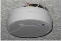
A knowledge-based system is a fundamental AI system that makes decisions purely based on rules. A traditional knowledge-based system comprises a large set of if-else rules that builds a decision tree and processes FDD queries efficiently. A semantic of a typical knowledge-based FDD system is shown in Figure 1. The collected sensor data is evaluated by maintainability rules. The evaluation results lead to the various maintenance decisions following a tree-alike structure.

Details are in the caption following the image

For example, following the escalator maintainability rules stated in Table 2: ‘The landing area of escalators and passenger conveyors should have a surface that provides a secure foothold for a minimum distance of 0.85 m (measured from the root of the comb teeth)’, the measurement data collected from the sensor can be easily evaluated as ‘satisfactory’ or ‘unsatisfactory’. Different evaluation results will arrive to different decisions for automated maintenance.

2. Elevators & Escalators - Escalator.
Problem Design Construction Maintenance
  1. Escalator and passenger conveyor related maintainability issues
  2. image
  3. Accumulation of debris within the escalator interior
  4. image
  5. Footwear getting stuck between steps
  6. image
  7. Good practice: Escalator cordoned off during maintenance operations to prevent unauthorised access
  1. Ensure that the landing area of escalators and passenger conveyors have a surface that provides a secure foothold for a minimum distance of 0.85 m (measured from the root of the comb teeth) in accordance with AS 1735.1 or equivalent.
  2. Ensure that the escalator and its surroundings have sufficient and adequate illumination. The supporting structure for escalators and passenger conveyors should be designed in accordance with BS EN 115-1, SS 626 or equivalent.
  3. Comply with the safety code for elevator design and construction in accordance with ASME A17.1/CSA B44, ISO 8100-20, BS 8899 or equivalent.
  4. Incorporate anti-climbing, anti-sliding, access restriction and deflecting devices to maintain safe operation in accordance with SS 626 or equivalent.
  1. Installation of escalators should be guided by the relevant standards and codes for safety and reliability in accordance with BS EN 115-1, SS 626 or equivalent.
  2. All machinery should be mounted securely and be defect free (e.g., should not have any oil leakage).
  3. To ensure safe operation without issues due to corrosion and wear and tear, all escalator components should be of durable and reliable make.
  4. All signs, inscriptions and notices should be made of durable materials in accordance with BS EN 115-1, SS 626 or equivalent.
  1. Ensure proper housekeeping of escalator to keep it clean and free of debris. Building owner/operator need to conduct monthly maintenance of escalators (including maintenance of safety switches, sensors, emergency stops, and handrails) in accordance with SS 626, BS EN 115-1 or equivalent. The annual inspection and testing should be performed by an independent authorised examiner (AE).
  2. Bar access to the escalator or passenger conveyor with suitable devices and notices/signage displaying “no access/no entry” during maintenance, repair works, or inspections, in accordance with BS EN 115-1, SS 626 or equivalent.
  3. Adopt the inspection criteria for safety of escalators in accordance with JIS A 4302. Refer to procedure for ride quality measurements of escalators and moving walks in accordance with BS ISO
  4. 18738-2 or equivalent.

A knowledge-based FDD system integrating traditional data-driven FDD framework treats the knowledge pool (Figure 1) as an expert system [9, 56]., where if-else rules are derived from maintainability rules. Following the existing rule-based system structures proposed in the related fields, such as [45, 57, 58], decisions for labeling various faults can be reached. The accuracy and performance of such FDD systems depend on the precision and reasonings of the rules. Compared with the existing rule-based systems, the maintainability rules proposed in this study are more precise and reasonable, consequently providing better results in terms of diagnostic accuracy.

3.2. Maintainability Rules as Inputs for Data-Driven FDD Systems

Data-driven FDD applied machine learning techniques to sensor data and performs automated classification with a pre-defined training process on the collected data. A typical data-driven FDD process is shown in Figure 2, where historical data containing both normal operational and faulty conditional data is received by the machine learning (ML) models. Two particular ML models are trained. The binary ML model handles the fault detection for facilities management, which classifies the future sensor data into normal or faulty classes. The multi-class ML model handles the fault diagnosis part, which classifies the faulty sensor data into different types of faults.

Details are in the caption following the image

Traditional FDD methods, as shown in Figure 2, assume completely no background knowledge of the maintainability of the facilities. The maintainability rules that we proposed in this study provide a great opportunity to improve the existing FDD approaches. The simplest way of extending the current FDD framework with the maintainability rules is to treat them as inputs for the ML models. We formalize the proposed extension of the existing FDD framework in Figure 3.

Details are in the caption following the image

In Figure 3, the traditional FDD framework has been improved by adding maintainability rules as inputs for both training and testing phases. Since ML models, in general, do not require background knowledge for classifications, the maintainability rules are served as additional inputs for both training and testing of the ML models. The maintainability rules have the potentials of enhancing the interpretation capability of the ML models as well as the prediction performance.

A concrete example of the proposed framework shown in Figure 3 is the three-layer Bayesian Belief Network (BBN) adapting the maintainability rules as an additional layer for FDD. The three-layer BBN is a three-layer neural network, calculating the probabilities of label assignment based on evidence and conditional probability. The details of the BBN construction can be found in [46, 47]. The internal structure of the BBN is illustrated in Figure 4, where expert knowledge is interpreted using maintainability rules as introduced in the Introduction Section (Section 1) and Section 4. For prediction probabilities calculated by neural networks, the maintainability rules provide evidence that influence the probability calculation. Therefore, the FDD accuracy will be improved significantly.

Details are in the caption following the image

4. Maintainability Rules Study for Facility Management in M&E Services

In this section, we summarize the maintainability rules following the expert knowledge of typical components in M&E services, namely, HVAC system, plumbing and sanitary system, fire safety, electrical system and elevator & escalator system collected through survey and interview results over 110 buildings in Singapore, including commercial, hotels, industrial, institutional, clinical and residential buildings. The maintainability rules summarize the preventive checklist based on expert knowledge as well as standards regionally or globally in all design, construction and operational stages of buildings. The maintainability rules are useful serving as the knowledge pool for the post-caution FDD approach or as the additional maintainability layer for a precaution FDD approach, as explained in Section 3.

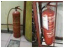
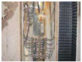
The maintainability rules for the chiller plant, the cooling tower, the air handling unit (AHU) and the air distribution, terminal system of the HVAC system are summarized in Tables 36, respectively. The maintainability guidance for general pumping issues, the water supply system and the water tank of the plumbing and sanitary system ae summarized in Tables 79, respectively. The maintainability issues for the fire detection, the fire hydrant system, the sprinkler system and the fire extinguishers of the fire safety (Table 10) are listed in Tables 1113, respectively. The maintainability rules for the switchgear, the standby generator, the artificial lighting, the lightning protection system (LPS) and earthing are summarized in Tables 1417, respectively. The general rules for the elevators and escalators, common faults for the elevators and escalators, the elevator safety, energy efficiency for the elevators and escalators and the maintenance for escalators, in general, are summarized in Tables 1821, respectively.

3. HVAC System - Chiller Plant.
Problem Design Construction Maintenance
  1. Chiller frequently unloading (stop-start); compressor not starting
  2. image
  3. Rust stain
  4. image
  5. Leaking condenser pipes
  1. Conform to the minimum requirements for air- conditioning equipment efficiency in accordance with SS 530: 2014, ANSI/ASHRAE/IES standard
  2. 90.1 or equivalent.
  3. Specify proper placement for installation of temperature sensors/probes to capture realistic average temperatures of spaces.
  4. Conform to the safety and environmental requirements for refrigeration systems in accordance with ISO 5149-1 or equivalent.
  1. For applications with high dynamic load conditions of a facility, install and commission chillers with variable speed drive (VSD) compressors.
  2. Ensure that schematics and maintenance regime of refrigerant leak detection system is handed over to maintenance personnel upon completion.
  1. Set up appropriate cut-in and cut-out temperatures in chiller to avoid frequent unloading.
  2. Inspect evaporator tubes for excessive oil, dirt or frost; check operating condition of expansion valve; check condenser tubes for air, dirt, scale, and sludge, and clean/purge if necessary. Check condenser water supply and cooling tower efficiency. Inspect overload relay, and the condition of high- pressure and low- pressure cut-outs.
  3. Carry out monthly inspection on refrigerant level to avoid low pressure cut-outs of chiller in accordance with ANSI/ASHRAE/ACCA standard
  4. 180 or equivalent.
  1. Insufficient cooling/slow cooling
  2. image
  3. Scale in condenser pipes
  4. image
  5. No insulation for chilled water pipe
  6. image
  7. Leakage of refrigerant
  1. Design chiller plants for recommended cooling
  2. Demand with provisions for future expansions guided by SS 553, SS554, AS1668.2, ISO16814 or equivalent.
  3. Comply with air conditioning plant optimisation strategies (e.g. high-efficiency chillers, aggressive condenser water reset, medium temperature chilled water loop, chilled water VFD pumping, etc.) in accordance with SS564-1 or equivalent.
  4. Use refrigerants with zero ozone depleting potential (ODP) or global warming potential (GWP) of less than 100 [7]. Recommend installation of leak detection system in critical areas of plant rooms.
  1. Cary out proper commissioning of chiller plant and set reasonable points. Perform post-installation monitoring of the installed instrument’s performance through the BMS (building automation system) or EMS (energy measurement system).
  2. Document as-built drawings (including concealed services) for building user phase. Prepare and handover maintenance checklists for service and repair of each instrument during commissioning. Refer to measures for recommended monitoring procedures for chiller efficiency in accordance with SS 591 or equivalent.
  1. Inspect temperature controllers and thermostatic control valve for any malfunctions and then reset.
  2. Perform routine inspection of condenser pipes. Carry out cleaning and servicing (de-scaling) if/when necessary.
  3. Routinely inspect insulation for any damaged/worn-out layers. Daily logging of chiller system to ensure system operates at optimum conditions. Any deviation from the intended chiller operation or alarms need to be attended promptly.
  4. Perform annual shutdown or overhauling in accordance with manufacturer’s guidelines (ANSI/ASHRAE/ACCA standard 180).
  1. Chilled water pipe and condenser pipe leakage and condensation
  2. image
  3. Leaking motor valve
  1. Adopt the pump system design calculation and recommend outputs in accordance with ISO 13612-1 or equivalent.
  2. Specify the use of unplasticized PVC pipes for cold water services/industrial use as in accordance with SS 141 or equivalent.
  3. Provide flow meters for chilled/condenser water loops.
  1. Ensure proper workmanship during pipe installation and testing, especially at joints.
  2. Perform proper insulation of chilled water pipes to avoid condensation.
  3. Use primary-only variable flow chilled water pumping systems in accordance with SS 564-1 or equivalent.
  1. Cary out quarterly check for pitting noise in pumps. Avoid harsh cleaning methods that may damage pipes or cause the thinning of pipes.
  2. Prepare maintenance checklist for flow meters (ultrasonic and full-bore magnetic in-line types) in accordance with SS 591, ISO 12242 or equivalent.
4. HVAC System - Cooling Towers.
Problem Design Construction Maintenance
  1. Biological fouling of cooling tower
  2. image
  3. Foaming in cooling tower basin
  4. image
  5. Scale and dirt build-up in fouled fills
  1. Provide a suitable cooling tower design to prevent dirt accumulation and stagnation.
  2. Minimise tower fan power and size of towers for close approach in accordance with SS 564-1 or equivalent.
  3. Provide automatic chemical dosing system to ensure acess hatches, level indicators mixers, pump etc. can be easily reached by personnel for maintenance and operation.
  4. Provide adequate reach to all parts of the cooling tower for cleaning so as to prevent bacterial growth.
  5. Specify locally green certified cooling tower water treatment system [8], but not limited to automated non-dispersant, non-chemical treatment etc. as it will minimise the downstream maintenance issues. The automated system with the capability of checking of the conductivity and other recommended parameters can be also linked to the building management system (BMS).
  1. Prepare and submit an operation and maintenance (O&M) manual
  2. For the chemical dosing system after the successful commissioning of the system.
  3. Install equipment to routinely observe chemical tank levels and the tank condition of the automated dosing system. During installation, ensure that access hatches, level indicators, mixers, pumps, etc. can be easily reached by personnel for maintenance in the operation phase.
  1. Perform frequent overall visual inspection and cooling tower sequencing. Clean tower fill, basin and drift eliminators. Conduct weekly check on fan motor; clean screen; make up water float and water sampling.
  2. Carry out monthly check of motor supports, fan blades, motor alignment.
  3. Check on condition of bearings and motor, as well as for nozzle clogging, annually. Clean cooling tower at least once a year.
  4. Perform monthly checks for legionnaire, scaling and corrosion in/of the condenser system. Disinfect and manually de-sludge cooling towers if required.
  5. Monitor water usage in cooling towers and review the efficiency.
  6. Ensure optimum scheduling of temporary shutdown and standby of cooling towers.
  7. Discharge used water from cooling owners into a sewerage system.
Water efficiency
  1. Consider collection of condensates for re-use.
  2. Take into consideration the cycles of concentration of the cooling owner used in order to reduce blow-down frequencies.
  3. Avoid uncontrolled water losses due to drift, splash, overflow etc.
  1. Ensure proper installation of float operated inlet valve to reduce frequencies of overflow.
  2. Link cooling towers in order to maintain water balance.
  3. Consider using solenoid operated inlet valves for cooling towers.
  1. Legionella outbreak
  2. image
  3. Outbreak on air-water surfaces of cooling tower
  4. image
  5. Cooling tower air intake blocked by organic matter
  6. image
  7. Testing the water for legionella
  1. Avoid redundant pipework, bends, and loops for cooling system design. Allow easy access to all parts of the system for maintenance [9].
  2. Minimise drift by enclosing cooling tower pond.
  3. Take the wind direction/distribution and the surrounding environment into account when designing the cooling system.
  4. Use non-corrosive, chemical-resistant, non- porous, smooth, opaque (to block sunlight) material to inhibit growth and proliferation of microorganisms.
  5. Design of cooling towers must be capable for preventing dirt accumulation and water stagnation.
  6. Accommodate suitable and efficient water treatment methods in the system’s design.
  1. Perform proper commissioning to ensure safe operation of cooling towers. Develop cooling tower maintenance manual including cleaning/water treatment/decontamination procedures and handover during commissioning.
  2. Ensure system is clear of dirt/debris/organic matter and clean before operation.
  3. It is presupposed that the control of legionella bacteria in cooling towers is in compliance with applicable statutory and regulatory requirements.
  1. Cooling tower’s water temperature should be monitored since elevated temperatures and moisture at air-water surfaces provide ideal conditions that may serve as a nutrient source for legionella growth.
  2. The chemical concentration limits of cooling tower effluents should be checked and in compliance with the relevant local standard.
  3. If cooling tower is not in use, it should be kept drained and dry. If not in use for more than 5 days, it should be drained, cleaned and disinfected before operating. Regular testing for legionella bacteria should be carried out and get water samples from the cooling tower pond in accordance with ASHRAE 12-2000, ANSI/ASHRAE
  4. 188 or equivalent.
5. HVAC System - Air Handling Unit (AHU).
Problem Design Construction Maintenance
  1. Air distribution system efficiency
  2. image
  3. Broken fan belt
  4. image
  5. Blue/grey formicary corrosion on Al-cu cooling coil
  1. The design of an AHU system must take into consideration energy efficiency and maintainability when selecting the system and its components. Design AHU in accordance with ANSI/ASHRAE/IES standard
  2. 90.1/SS 553 or equivalent.
  3. Fan power limitation requirements in mechanical ventilation systems to comply with SS 553, AS 1668.2 or equivalent.
  4. Specify minimum performance for air- conditioning equipment (including test procedure) in accordance with SS 530, ANSI/ASHRAE/IES standard 90.1 or equivalent. Propose a biological film application on cooling coil.
  1. It is presupposed that the installation (and subsequent operation) of the AHU is in compliance with statutory and regulatory requirements.
  2. For the vibration control of fan systems, refer to CP 99 for the installation/commissioning in accordance with ISO 9996 or equivalent.
  3. Install/integrate AHU system components (e.g. VFD, control dampers/actuators) off-site to ensure quality installation.
  1. Clean dirt from impeller, fan scroll and blower blade, washable filters, filter frames and AHU frame slot. Clean cooling coil face with water. Flush with chemical cleaner, but avoid over dosage. Chemical wash should be carried out followed by thorough cleaning with water. Check for any dents on the coil fins. Comb/replace as needed. Clean off any hardened and dirty grease or grime from fan and motor shaft and lubricate properly.
  2. Do not use AHU rooms for storage and avoid housing installations that are not associated with the air- conditioning system, in accordance with SS 553, AS
  3. 1668.2 or equivalent.
  1. Noisy operation and excessive vibration
  2. image
  3. Noisy fan motor
  4. image
  5. Good practice: Install a connection box on AHU for vibration monitoring
Careful design is necessary to reduce vibration disturbances caused by impact force. Conform to noise control and elimination guidelines. Use principles of vibration control in determining noise control measures in accordance with SS CP 99, AHRI 260, ISO 9996 or equivalent.
  1. Use acoustic silencers, shock isolators, machine enclosures and partition walls to reduce noise disturbances. Use vibration isolators/mounting of equipment to minimise transmission of vibration from machine to load-bearing structure of the building in accordance with ANSI/AHRI Standard 260, CP 99, ISO 9996 or equivalent.
  2. Recommend installing vibration monitoring equipment for AHU to assist in predictive maintenance.
  1. Inspection should be carried out to determine noise levels (ANSI/AHRI standard 260). Inspect chiller plant with maintenance experts if abnormal sound occurs.
  2. Isolation/mounting systems should be provided to reduce mechanical vibration and shock in accordance with ISO 2017-1 or equivalent. Vibration from bearings, and sliding and rolling friction could be reduced by maintaining minimum clearances and proper lubrication in accordance with CP 99, ANSI/AHRI Standard
  3. 260 or equivalent.
  4. Regular monitoring of AHU fan vibration should be carried out and compare with the vibration readings specified in ISO 10816-3 or equivalent.
6. HVAC System - Air Distribution and Terminal Systems.
Problem Design Construction Maintenance
  1. Dirty and mouldy ductwork
  2. image
  3. Mould growth in duct
  4. image
  5. Damper inside AHU collecting condensation, leading to biological growth
  1. Conform to the design requirements for air duct systems, including for fittings and accessories, in accordance with SS 553 or equivalent (where consideration is given to air velocities in ducts, materials and construction method, etc.). Fulfil the compliance requirements of thermal insulation for pipework. Comply with the ductwork seal requirements. Ensure that rigid ducts are manufactured from steel, aluminium, glass-fibre or mineral wool, or other approved materials. Conform to the minimum duct
  2. insulation R-values for cooling supply/return ducts in accordance with SS 553, AS 1668.2 or equivalent.
Adopt the construction and installation requirements for air duct systems and their fittings and accessories. Ensure that the ducts or duct linings (where glass fibre or mineral wool is exposed to the air stream) are suitably protected to prevent fibre erosion. The ducts should be sturdily supported - provide metal hangers and brackets for supporting ducts. Guarantee that the inner surfaces of the ducts for supply and return air are smooth and resistant to abrasion in order to reduce dust accumulation in accordance with SS 553, AS 1668.2 or equivalent.
  1. Carry out noise and air loss check when necessary.
  2. Perform testing and rating of performance of ducted air-conditioners (ventilation, exhaust and leakage air flow) in accordance with ISO/FDIS 13253.
  3. Carry out yearly check of ducting insulation.
  4. Perform duct leakage test as per industry requirements in accordance with SS 553, AS 1668.2 or equivalent.
  1. Filter media choked at the air terminal
  2. image
  3. Choked filter
  4. image
  5. Bent aluminium fin
  1. Provide locations for intake and return air terminals. Adopt the minimum standard air filter requirements with regard to the use of air filters for cleaning outdoor air so that no unfiltered air can enter the air handling system. Follow the recommended use of secondary air filter of 80% dust spot efficiency in accordance with SS 553, AS 1668.2 or equivalent. Use of locally green certified energy efficient air filters (SGBP) if space provision is adequate [8].
  2. Provide sufficient access space for easy cleaning and replacement of filters.
  3. Provide a display system for temperature and relative humidity at each floor and at each tenanted area.
  1. Carry out an alternate efficiency test method for filters in accordance with ISO 29463-5 or equivalent.
  2. Perform a one-time vet airflow test during commissioning and keep proper record of the report to ensure the cooling capacity is adequate in accordance with design load and applicable statutory and regulatory requirements, and that the noise level is within the desired level in accordance with applicable statutory and regulatory noise pollution standards.
  1. Monitor air pressure and pressure drop across the filter and replace filter when needed. If filter is heavily dented, the filter should be replaced.
  2. Cary out leakage test to test filter for local penetration in accordance with ISO
  3. 29463-1.
  4. Carry out monthly check and observe the dust accumulation level in ducts or grilles.
7. Plumbing & Sanitary Systems - General Pumping.
Problem Design Construction Maintenance
  1. Water supply — General defects
  2. image
  3. Leaky joint wetting the floor
  4. image
  5. Ceiling damaged by pipe leakage due to haphazard pipe laying
Adopt the pipe sizing requirements based on hydraulic design and pump performance. Provide allowance for head loss, and frictional loss due to internal roughness, loss at fittings, turbidity, surge and pumping facility. Do not oversize piping as slow flow will cause stagnation. Specify standard fittings such as tees, elbows, etc. in accordance with BS 7291-1, BS EN 598, BS EN 545 or equivalent.
  1. The installation of water fittings should comply with the requirements as stipulated in SS 636 pr BS 8558. It is presupposed that it is also in compliance with applicable statutory and regulatory requirements.
  2. Fittings that are fabricated by welding together segmented pieces are not recommended. Avoid haphazard pipe laying.
  3. It is presupposed that all water tanks, pipes and fittings are in compliance with applicable statuary and regulatory requirements.
Perform thorough investigation to check compliance with SS 636 and BS8554. Monthly inspection of water flow rate and pressure should be carried out, and position and functioning of valves. Maintenance inspections of the pipe installation should be carried out and identify/rectify physical defects such as broken pipe braces, dents, or leaks in accordance with BS 8558, BS EN 806-5 or equivalent.
  1. Leaky joints in inaccessible areas
  2. image
  3. Leaking pipe above ceiling
  4. image
  5. Leaky water pipes in the ceiling
  1. Sufficient distance (>400 mm) should be maintained from structure or other services running parallel to each other, for easy maintenance and to avoid interference or damage.
  2. Pipes should be of adequate strength and durability, and adequately supported in accordance with BS 8558, SS 636 or equivalent.
  1. Ensure that the pipes and fittings are stored and installed in accordance with manufacturer’s instructions.
  2. Prevent any interior contamination. If contamination occurs, clean before installation.
  3. Take special care when joining two dissimilar materials.
  1. Perform routine monitoring of piping system and check for any possible water seepage through the building fabric in accordance with BS 8558 : 2, BS EN 806-5 or equivalent.
  2. Repair the pipe joints properly using the correct jointing method. Tighten valve stems by replacing/fitting any missing gasket/washer.
8. Plumbing & Sanitary Systems - Water Supply System.
Problem Design Construction Maintenance
  1. Corrosion and scaling of pipe/valve
  2. image
  3. Scaling in pipe
  4. image
  5. Corrosion of pipe flange
  1. Specify materials that are resistant to corrosion and non-reactive to the conveyed water and surrounding ground in a cadence with BS EN 545, BS EN 598 or equivalent, and that do not impart any taste or toxicity to the water in accordance with BS EN 1796, SS 375-1 or equivalent.
  2. Use of single material for the entire system is preferable for easy connection/jointing. Specify pipe system material that does not react with the pumped medium.
  1. Pipe penetrations and joints should strictly comply with manufacturer’s instructions.
  2. Jointing material should not enter pipe. Caulking at penetration sleeve should be made watertight.
  3. Proper installation should be fulfilled while ensuring that the protective coating is not lost/damaged during installation in accordance with BS 8558, SS 636 or equivalent.
  1. Carry out quarterly chemical and bacteriological analysis of water used [10].
  2. Perform monthly check of water supply for visual signs of leakage, scaling and corrosion of pipes, joints, valves, taps and mixers. Increase frequency of inspection for damp or polluted areas in accordance with BS 8554 or equivalent.
  3. Carry out monthly inspections and clean off/remove any rust or scale. Re-paint parts in a timely manner if needed in accordance with BS EN 806-5 or equivalent.
  1. Damaged piping
  2. image
  3. Burst outdoor pipe
  4. image
  5. Damaged outdoor pipes
  6. image
  7. Corroded galvanised piping
Pipework design should consider factors such as the choice of material, rate of flow, accessibility, protection against damage, corrosion, avoidance of airlocks, water hammers, noise transmission, unsightly arrangements, vibration and expansion of fluid, stress and strains, etc. in accordance with BS EN 1057, BS EN ISO 21003-2, BS EN ISO 21003-3, BS EN ISO 21003-5 or equivalent. Provide adequate longitudinal support to pipe installations below ground to cater for loads and traffic vibration.
  1. For underground pipe laying, fully compact bedding prior to installation and maintain the correct depth of trench, gradient, width and bottom condition.
  2. Properly align pipe work and use suitable joints. Ensure careful backfilling at an adequate depth for underground pipe laying. Completed sections should be tested for defects using leakage tests and should be rectified by the contractor as required. Maintain proper water pressure in piping system to avoid bursting from over pressurisation.
  1. Carry out thorough cleaning and disinfection of service pipes on a monthly basis, and clean the main pipes semi-annually. If required, removal of blockage with manual cleaning method (e.g., plunger, drain rod, spring auger) should be performed.
  2. Carry out chemical de-scaling quarterly (care should be taken so that it does not harm the pipes or jointing by giving consideration to chemical type or contact time). Perform maintenance schedule to check for clogged outlets in accordance with BS 8558, SS 636 [11].
  3. Isolate all leaks and faulty water pipes and fittings first to prevent water wastage before they are being repaired by a licensed plumber. All repairs should be done as soon as possible.
  1. Water hammer
  2. image
  3. Cast iron pipe cracked by water hammer
  4. image
  5. Thrust bearing of a submersible pump ruined by water hammer
  1. Avoid water hammers (water pipe banging) in pipework design in accordance with JIS A 4422, BS EN 1057 or equivalent.
  2. Design airlocks and low supply pressure to minimise turbulent flow.
  3. Evaluate the required strength of valves and tightness of body and in between the inlet and outlet chamber in accordance with BS EN 1567 or equivalent.
  1. Note that a water hammer may arise when the electric valves on appliances or single control valves are shut off fast. Although all noises due to water flow and pipe expansion cannot be removed, the contractor is responsible for fastening the pipes properly and commissioning valves/actuators to minimise the water hammer.
  2. Install check valve to control the creation of a vacuum in discharge pipe in accordance with BS EN 16767, BS EN 545 or equivalent.
  1. Monthly pressure test should be carried out by operating pump for min. 1 hr with 125 m head or 150% of working pressure (whichever is greater) and check for any individual leakage or overall leakage.
  2. Semi-annual pressure test should be carried out for sewage pumps.
  3. Additional bracing or anchor block support at bends and branches should be provided in order to withstand the hydraulic thrust.
  1. Excessive vibration
  2. image
  3. Insufficient vibration damping causing wear-out of parts
  4. image
  5. Dented pump impeller
  1. Ensure that pumps are properly sized to meet the required pressure. Head loss, frictional loss and loss at bends should also be considered.
  2. Sewage pumps should be able to handle long and fibrous material. If required, pre-treatment (e.g., crushing) is provided.
  3. Specify variable speed drives (VSD) that are able to handle both maximum and variable demand. Ensure that the pump is mounted on an isolation bed (e.g., 150 mm insulated padding) and that no site adjustment in height or position should be done.
  1. The installation of pumps should be adopted in accordance with manufacturer’s instructions. Ensure proper construction of isolation beds and installation/mounting of equipment.
  2. Special attention should be given for tightness of joints, and alignment of bearings and pipes.
  3. Testing and commissioning of the auto and manual interchange of duty and standby pumps should be carried out.
  1. Lubricate pump parts with oil or grease in accordance with manufacturer’s instructions.
  2. Carry out routine checks, clean motor starter and all heavy current contacts, and replace worn parts.
  3. Visually check for any damage or missing parts (screw, nuts, strainer, etc.).
  4. Ensure that after installation, pump is tested with power on mode for any unusual vibration, noise, leakage or burnt smell.
Sensor self-closing delayed-action basin taps To specify the display contact numbers of maintenance staff so that users can report any faulty, leakages or damaged taps to them for immediate rectification. To ensure the display contact numbers of maintenance staff so that users can report any faulty, leakages or damaged taps to them for immediate rectification. Carry out routine checks to ensure that sensor self-closing delayed-action tap can function properly and when the tap is activated, the water is automatically cut-off after a pre-set period of time. The tap should automatically stop functioning during power failure in accordance with SS 448.
Self-closing delayed-action basin taps To specify the display contact numbers of maintenance staff so that users can report any faulty, leakages or damaged taps to them for immediate rectification. To ensure the display contact numbers of maintenance staff so that users can report any faulty, leakages or damaged taps to them for immediate rectification. Carry out routine checks to ensure that self-closing delayed-action tap can function properly and that the water is automatically cut-off after a pre-set time in accordance with SS448.
Dual-flush low-capacity flushing cisterns To specify the display contact numbers of maintenance staff so that users can report any faulty, leakages or damaged taps to them for immediate rectification. To ensure the display contact numbers of maintenance staff so that users can report any faulty, leakages or damaged taps to them for immediate rectification. Ensure that flushing cistern can function properly in accordance with SS574 and check for signs of leakage, defect or damage (including any leakage, defect or damage at the outlet and inlet valves).
Sensor urinal flush valves To specify the display contact numbers of maintenance staff so that users can report any faulty, leakages or damaged taps to them for immediate rectification. To ensure the display contact numbers of maintenance staff so that users can report any faulty, leakages or damaged taps to them for immediate rectification. Carry out routine checks to ensure that sensor urinal flush valves can function properly and discharge the flush volumes not exceeding those specified in SS 636.
Sensor WC flush valves To specify the display contact numbers of maintenance staff so that users can report any faulty, leakages or damaged taps to them for immediate rectification. To ensure the display contact numbers of maintenance staff so that users can report any faulty, leakages or damaged taps to them for immediate rectification. Carry out routine checks to ensure that sensor WC flush valves can function properly and discharge the flush volumes not exceeding 4.5 L per flush as specified in SS 636.
9. Plumbing & Sanitary Systems - Water Tank.
Problem Design Construction Maintenance
  1. Unauthorised/poor accessibility
  2. image
  3. Lack of safety cover and security lock in water tank
  4. image
  5. Good practice; make provisions for access to water tank(s) for maintenance and/or inspection
  1. Provide a permanent climbing ladder for easy inspection and cleaning of interior. If the ladder rises a vertical distance of more than three metres, then additional fall prevention measures should be considered such as install a safety cage [12, 13]. Provide a minimum of 600 mm space, all around the sides of the tank with at least 1.2 m space from the top of the tank to the ceiling for maintenance, repair and inspection purposes. Install minimum possible number of openings to each compartment; each opening should be fitted with a cover/trapdoor. Sanitary pipes should not be placed above potable water storage tank. Backwash water from swimming pool filter system backwash holding tank should be discharged into a sewerage system.
  2. Provide corrosion- resistant, mosquito-proof netting for overflow pipe/vent.
  3. Design a series of tanks instead of one large tank, to meet demand for isolation during maintenance, for ease of access.
  1. Ensure there is adequate access space to and around the tank. Edge protection e.g., guardrail should be provided to prevent personnel from falling from open sides of the tank [12, 13].
  2. Ensure that the tanks are not compartmentalised, so as to avoid the shutting off of the whole supply during cleaning (inconveniencing building users).
  3. For the purpose of safety and security, provide a lock to water tank, so that only authorised personnel can access it. Ensure that the access is easy and safe, and for authorised persons only.
  4. Comply with all security measures in accordance with SS 636 or equivalent.
  1. Carry out general housekeeping within and around the tank room to remove any obstructions to maintenance access. Perform monthly cleaning of wash-out pipes to ensure proper flushing out of the water.
  2. Remove sand and dirt deposits in cisterns and tanks. Remove rust stains and repaint affected parts as recommended. Prevent dirt, dust, insects, birds, etc. from entering the tank.
  3. Carry out thorough cleaning and disinfection of tank interiors semi-annually.
  1. Leakage from water tank
  2. image
  3. Corrosion of bolts and subsequent leaking
  4. Of GRP tank
  1. Ensure the proper design detailing of pipe penetrations at the tank to avoid leakage.
  2. Avoid cracks in concrete tanks; ensure water-tightness, through proper structural design.
  3. Specify appropriate water stops and sealants where pipes penetrate the structure.
  4. Maintain a minimum air gap above maximum water level in accordance with SS 245, BS EN 13121-3 or equivalent.
  1. Construct the tank body in accordance with specifications (additive, coating, and lining), and render as a monolithic and watertight container. Maintain the exact size and positions of installed devices in accordance with SS 245, BS EN 13121-3 or equivalent.
  2. Commission tank by testing for water-tightness; check for any leakage, seepage, and water loss. Ensure that all components are functioning well.
  1. Inspect drainage lines and basin.
  2. Carry out routine checks for rusting of metal tanks and apply anti-corrosive paint/coatings where necessary.
  3. Perform routine checks on float valve and liquid level indicator for damages to avoid potential overflow.
  1. Corroded water tank body
  2. image
  3. Corroded tank body
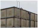
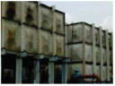
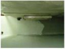
The body of the water tank should be made of watertight and corrosion-resistant material, such as reinforced or pre-stressed concrete, steel, and glass fibre reinforced plastics in accordance with SS 245, BS EN 13121-3 or equivalent. Structure of water tank should be constructed with adequate strength and be free from any deformation. Refer to BS EN 10088-2 for standards for a Stainless-Steel Sectional Water Storage Tank (Minimum Grade 316).
  1. Ensure that the parts (e.g., pipes/strainer) and fittings (e.g. ball float, valves) are corrosion-resistant and can be replaced over time.
  2. Perform timely re-application of coatings to avoid peeling and delamination of coat
  1. image
  2. Corroded and damaged water tank
  3. image
  4. Corroded water tank
  1. Surface treatments, waterproof coating, or lining coating should be specified to resist water seepage and weathering.
  2. Ensure that such finishes do not affect the stored water’s quality of hygiene in accordance with BS 8558, SS 636 or equivalent.
The water storage tank’s installation should be certified by a professional engineer to ensure that it is structurally sound with regard to hydrostatic pressures, deflection and leakage. Use disinfectant to clean water tanks in accordance with BS EN 805 or equivalent. Once disinfectant has been sprayed on inner surfaces and pipes for the designated period, it should be thoroughly cleaned/removed.
  1. (for steel tanks), and water seepage (for concrete tanks).
  2. Use disinfectant to clean water tanks in accordance with BS EN 805 or equivalent. Once disinfectant has been sprayed on inner surfaces and pipes for the designated period, it should be thoroughly cleaned/removed.
  1. Overflow of water
  2. image
  3. Overflow of water as seen from underneath a tank
Decision on the size(s) of the tanks should be made based on water demand, supply, probability of pump failure, time needed for repairs, ratio of peak hours to average flow rate, provision of alternative supply or storage, etc. in accordance with BS 8558, SS 636 or equivalent. Ensure that the tank is capable of handling various loads (as applicable) without showing cracks, stress or deformation in accordance with SS 245, BS EN 13121-3 or equivalent.
  1. Carry out monthly inspections to check the operation of float valve or any other effective device for controlling the inflow of water. All valves should be periodically operated to ensure that the working parts are moving freely in accordance with BS 8558, SS 636 or equivalent.
  2. Inspect condition of overflow warning alarm for the water tank. Inspect the condition of warning alarm which indicates when water levels fall below 50 mm from the invert level of the pipes.
Potable water tanks Cleaning and disinfection of potable water tanks should be adopted in accordance with SS 636 or equivalent.
10. Fire Safety - Fire Extinguishers.
Problem Design Construction Maintenance
  1. Poor discharge of portable fire extinguisher
  2. image
  3. Low pressure indicated in the fire extinguisher. This often leads to poor or no discharge
  4. image
  5. Extinguishing cone missing
  6. image
  7. Fire extinguishers not kept properly and not secured
  1. The locations and number of portable fire extinguishers are to be based on the maximum travel route in accordance with SS EN 3 Series, BS 5306-8, ISO 7165 or equivalent.
  2. Access to or visibility of extinguishers should be unobstructed. Extinguishers should be visible along an escape route (preferably near room exits, along corridors and staircases, in lobbies, and on landing).
  3. The extinguishers’ body and the parts should be of approved quality to prevent rusting, early damage or deterioration in accordance with BS EN 3 series).
  1. Ensure the proper positioning (designated location, hung properly with label facing out) of fire extinguishers.
  2. For installation of small fire extinguishers (≤4 kg), hang on the wall with hanger or bracket such that the handle is about
  3. 1.5 m from floor. Hangers should be securely fixed.
  4. For installation of heavier fire extinguishers (≥4 kg), ensure carrying handle is about 1 m from floor and the arrangement will not hurt the person carrying it. Parts should be attached in accordance with manufacturer’s instruction.
  1. Conduct regular servicing to confirm required working condition. (Refer to the recommended schedules for maintenance in accordance with BS 5306-3 or equivalent.
  2. Conduct monthly inspection to ensure that the pressure gauge is in operative range and check for any sign of corrosion of the body of the extinguisher. Adopt the recharging frequency in accordance with the type of extinguisher.
  3. Adopt charging, testing and maintenance of fire extinguishers in accordance with SS 578 specifications or equivalent. Extinguishers should be recharged with the same agent only. No mixing or cross contamination allowed and no overfilling in accordance with BS 5306-9, NFPA 10 or equivalent.
  1. Fire door malfunctioning
  2. image
  3. Self-closing closer
  4. image
  5. Exit door obstructed by stacking of material
  1. Fire door should be selected in terms of stability, integrity, insulation and installed in accordance with SS 332, NFPA 80 or equivalent and in compliance with applicable statutory and regulatory requirements.
  2. Modifications to fire doors are not allowed unless in accordance with SS 332 or supported by assessment report from an accredited testing laboratory.
  1. Fix fire door in accordance with manufacturer recommendation. Fire door should be the same make and model as the tested prototype. Door frames installed during wall construction should be thoroughly grouted in cavity as deeply as possible with corrosion-proof anchor. Screws for attachment should be driven properly, and not hammered or placed in other positions in accordance with SS 332, NPFA 80 or equivalent.
  2. Ensure proper workmanship to avoid damaging/jamming/sagging door (e.g., tilted hinge).
  1. Inspect fire doors at least once a year, to ensure that self-closing mechanism functions as intended at all times. Check for and remove any door stoppers, or materials stacked near or by the fire exit door. Remove any obstructions.
  2. Check integrity of door leaf and frame for superficial damage, structural damage and excessive bowing or deformation. Inspect hinges, latches, door closer, bolts and pull handle weekly. Automatic release mechanisms should be tested in accordance with BS 5839-3 or equivalent.
  3. Ensure that egress is unobstructed in case of emergency evacuation in accordance with evacuation plan and NFPA 101 or equivalent.
11. Fire Safety - Fire Detection.
Problem Design Construction Maintenance
  1. Faulty fire alarm panel
  2. image
  3. Fire alarm system fault indicated in fire panel. A faulty fire panel can cause fire incidents to go unmonitored
  4. image
  5. Control panel displaying fault message and indicating that detectors are offline
  1. Design system to accommodate false alarm management in accordance with SS 645 (formerly CP 10) and applicable statutory and regulatory requirements [14]. Maintain the alarm system in accordance with manufacturer’s recommendations. The provision of alarm verification feature (AVF) and its functional requirement is covered under SS 645, subject to final approval from the relevant regulatory body to use it.
  2. Locate fire alarm panel in corrosion resistant cabinet without any exposure to excessive dampness. Fire panel connectivity should be independent and compatible with the building automation system (BAS).
  3. Specify red wiring for fire alarm system. Segregate from other ELV cables to remove electromagnetic interference.
  4. Use alarm verification features to reduce incidence of false alarms.
  1. Identify circumstances that can lead to a high rate of false alarms and inform both the designer and user. Check to ensure acceptable levels of false alarms during commissioning in accordance with SS 645, BS 5839-1, BS 5839-6 or equivalent.
  2. Install neatly and protect with sleeve in accordance with manufacturer’s requirements (care to be taken in concealed spaces).
  3. For the protection of joints in junction box, refer to minimum joint requirements.
  1. Conduct regular testing and inspection of fire alarm panel in accordance with SS 645, BS 5839-1, BS 5839-6 or equivalent.
  2. Conduct daily check to ensure normal operation, and to record and rectify any faults. Perform weekly tests to check battery and voltage conditions. Conduct monthly simulation of zonal fire and fault conditions. Clean fire alarm panel for proper operation and visibility (NFPA 72).
  3. Keep fire panels safe and secure from unauthorised tampering.
  1. Faulty manual call point
  2. image
  3. Dirty manual call point at an institutional building
  4. image
  5. Damaged manual call point
  1. Designate locations of manual call points along all exit routes and at
  2. final exits in accordance with BS 5839-1, BS 5839-6 or equivalent.
  3. Manual call points should be located in such a way that a person should not have to travel more than
  4. 45 m along an escape route to reach a manual call point, when the layout of the building is known. Each manual call point should be positioned 1.4 m (+/-200 mm) from floor level in accordance with BS 5839-1 or equivalent.
  1. Ensure that manual call points are securely mounted and properly aligned in accordance with SS645 (formerly CP 10) or equivalent.
  2. Upon installation, test the system (e.g., three- second response test for manual call point, battery removal test, etc.) in accordance with BS 5839-1, BS 5839-6 or equivalent.
  1. Conduct monthly test of manual call points on all alarm zones to ensure each part is functional, and especially check whether the remote auxiliary facilities are initiated or not.
  2. Monitor power supply and faulty wiring of call points and other elements of the fire detection system.
  1. Faulty fire detector
  2. image
  3. Dirty and damaged fire detector
  4. image
  5. Faulty, corroded and improperly installed detector
  1. Adopt the fire detection system requirements and applicable statutory and regulatory requirements [14] and in accordance with SS 615, ISO 7240 series, BS 5839-1, BS 5839-6 or equivalent. Ensure detectors are accessible for maintenance and replacement. Implement the selection of heat, smoke, and flame types based on requirements on-location. For decisions regarding the number of fire detectors, and their location and spacing design requirements,
  2. refer to SS 575, BS 9990 or equivalent.
  1. Ensure the proper fitting of each fire detector, to avoid misalignment or damage caused by shock.
  2. Ensure quality workmanship so as to avoid detector obstruction and or detector being covered by paint.
  3. Remove paint, dust or any foreign material that can affect its function from detector.
  1. Practice proper housekeeping to maintain cleanliness and avoid obstructions (especially at poorly accessible points).
  2. Inspect fire detectors weekly, and conduct monthly fire alarm simulations from a randomly selected detector to check the entire system.
  3. Perform annual test of 20% of all detectors; all detectors will be inspected over a five-year period in accordance with SS 645, BS 5839-1, BS 5839-6 or equivalent.
  1. Inaudible/unidentifiable alarm1
  2. image
  3. A site damaged by fire; fire propagated due to alarm system’s failure to signal in time
  1. Design fire alarm system (e.g., location, type and number of alarms) in accordance with SS 645, BS 5839-1 or equivalent and emergency voice communication system in accordance with SS 546, BS 5839-9 or equivalent.
  2. Select alarm sound that is distinguishable from general clutter. Use a visual alarm with excessive background noise.
  3. Propose incident communication facilities in accordance with SS ISO
  4. 22313 or equivalent and determine internal/external communication needs (e.g., through PA system integrated with iBMS) in accordance with SS ISO
  5. 22301 or equivalent.
  1. Establish, implement and maintain procedures for warning and communication (e.g., life safety); and set incident communication procedures in accordance with SS ISO 22313 or equivalent.
  2. Link lifts with audible warnings and emergency detection system and BMS, for emergency evacuation in accordance with ISO/TR 25743 or equivalent.
  3. Installation and cabling of fire alarm devices should be done in such a manner where in the event of a fault, at least one sounder located within the vicinity of the control and indicating panel will remain in operation in accordance with BS 5839-1 or equivalent.
  1. Inspect alarms for defects (e.g., loose or blocked gong bolt, damaged or corroded alarm, alarm spoilt by temperature fluctuations, etc.).
  2. Conduct annual check of all installed speakers, amplifiers, and connecting appliances (including cables) and keep records.
  3. Conduct routine check of fire alarm panel indicator bulb operation and battery according with NFPA 72 or equivalent.
  4. Perform real time monitoring and management of system performance.
  1. Malfunctioning or damaged backup power/lighting
  2. image
  3. Damaged exit signage; may interfere with egress during evacuation
  4. image
  5. Good practice: Regularly test emergency exit signs to ensure that they are in working order
  1. Design emergency power supply systems in buildings in accordance with SS 563-2 or equivalent; and emergency lighting fixtures in accordance with SS 563-1, BS 5266-1, BS EN 50172, BS 5266-8, AS/NZS 2293 SET or equivalent. Building emergency generator supply should be able to back up the emergency voice communication system in accordance with SS 546, BS 5839-9 or equivalent.
  2. Consider the use of a standby generator solely to provide power to emergency lighting systems, or in addition, to meet requirements other than those directly associated with emergency lighting.
  1. Requirements for the installation of emergency power supply systems in buildings should be adopted in accordance with SS 563-2, BS EN 1838, BS 5266-1 or equivalent.
  2. Individual luminaires should be mounted to avoid glare and if possible, should be positioned at least 2 m above floor level (measured from floor to the underside of the luminaires).
  3. The horizontal illuminance on the Centre line of any exit cannot be less than 0.5 lux. A fuel supply should be readily available to ensure that emergency lighting operates continuously for the rated period following the failure of normal power supply in accordance with SS 563-2 or equivalent.
  1. Ensure the maintenance of emergency power supply systems in buildings. Conduct a monthly manual test of emergency lights and replace batteries or lamps as soon as a fault is detected in accordance with SS 563-2, AS/NZS 2293.2/AMDT 3 or equivalent.
  2. Conduct monthly fire simulation test. Simulate failure of main power supply and test the efficiency of the standby battery.
  3. Ensure visual and audible fault signals are activated once the battery is disconnected.
12. Fire Safety - Fire Hydrant System.
Problem Design Construction Maintenance
  1. Fire hose damaged (cut kink, leak, missing part, abrasion)
  2. image
  3. Haphazard winding
  4. image
  5. Damaged hose reel cabinet
  6. image
  7. Damaged hose reel
  8. image
  9. Damaged fire hose coupling
  1. Ensure that the fire hose reel is suitable for the particular use of the facility in question, and that it is in accordance with BS EN 694, BS EN 1947 or equivalent.
  2. Adopt the technical quality acceptance for fire hoses in accordance with BS 6391.
  3. Fulfil cabinet specification (Size and mounting) in accordance with standard guidelines. Follow the distribution and number of fire hose reel cabinets in accordance with SS 575, BS 9990, NFPA 14 or equivalent.
  4. Adopt authority’s stipulated requirements if water supply is taken directly from authority’s water main.
  5. Ensure that access to or visibility of fire hose is not obstructed.
  6. Use maintenance-free fireproof material for the fire hose cabinet. The location should allow for 180° opening of cabinet door. The wall mounted type is only allowed in riser main shaft.
  1. Protect hose reels from mechanical damages. The reel should be mounted overhead, but the nozzle retainer, hose guide and inlet valve must be kept at 900 mm above finished floor level in accordance with BS 9990, SS 575, NFPA 14 or equivalent.
  2. During commissioning, flush out the hose to remove harmful matter.
  3. Conduct flush out test to remove any kink or knot and to ensure that all valves and nozzles are operational.
  4. Ensure that reel brackets are firmly fixed, so that the hose can be used properly.
  1. Perform proper housekeeping and avoid mishandling.
  2. Check for corrosion/leakage (of drum) once a month and ensure that hose, nozzle, stopcock, hinges, break glass device and cabinet are in acceptable working condition. Lubricate as required.
  3. Conduct monthly water flow pressure test and annual hydrostatic test in accordance with BS EN 1402 to check for defects or leaks, especially if the hose has been exposed to chemical or severe stress. During the test, the hose is completely run out and subjected to operational pressure. After the test, it should be dried and properly secured with a Velcro strap.
  4. Ensure that fire hose is stored in a cool, dry place in accordance with ISO 2230 or equivalent.
  1. Accessibility problems (difficulty in accessing fire hydrant)
  2. image
  3. Inaccessible hydrant points due to positioning
  4. image
  5. Improper housekeeping practices, and storing of combustible material in wet riser
  1. For the location and number of fire hydrants, refer to the applicable statutory and regulatory requirements [14].
  2. Adopt the positioning of breeching inlets as close as possible to rising main/hydrant in accordance with BS 9990, SS 575, NFPA 14 or equivalent.
  3. Ensure that the locations are accessible, with no obstructions from parking, loading bays, landscaping, building elements, etc.
  4. Provide protection to hydrants from mechanical damage.
  5. Specify easily visible/identifiable signage and colour in accordance with SS 508-3, ISO 3864-1 or equivalent.
  1. Installation should be secure and safe, with special consideration given for potential sources of damage.
  2. Connections and position of valves should be guided by specifications. Risers must be securely anchored before any pressure or flow test is performed.
  3. Hydrants should be made operable immediately after completion and should be tested to protect the construction site.
  4. Mounting height of hydrant and breeching inlet should be strictly maintained during installation in accordance with BS 9990, SS 575, NFPA 14 or equivalent.
  1. Perform proper daily housekeeping practices at hydrant points to remove obstructions (debris, stacked material) that impede accessibility.
  2. Ensure that the storage tanks are accessible for maintenance. Ensure that the valve pit is accessible for inspection and cleaning.
  3. Conduct semi-annual check for rust, dirt, or foreign material on valves, or other operating parts; as well as clean, paint and lubricate as required.
  4. Ensure that additional building elements, landscaping, etc. (during building operation and maintenance phase) do not impede accessibility to hydrant points in accordance with BS 9990 or equivalent.
  1. Faulty fire hydrant point (damaged, jammed, leaky)
  2. image
  3. Damaged hydrant
  4. image
  5. Damaged and unusable breaching valves
  1. Materials that are strong and rust-proof (e.g. gunmetal parts) should be specified for the construction of hydrant pillar, in accordance with BS EN 1982 or equivalent.
  2. The rising main and other pipework are in compliance with applicable statuary and regulatory requirements.
  3. Pit covers on roadways should be able to withstand vehicular load in accordance with BS 9990, SS 575, NFPA 14 or equivalent.
  1. Ensure the proper installation of all components (parts-stem, cap, plug, thread, etc.) without damaging them.
  2. Lubricate and paint for additional protection.
  3. Tighten outlet properly after commissioning and testing.
  1. Conduct weekly check of isolating valves to ensure that they are kept locked in open position daily and that breeching inlets are functioning in accordance with NFPA 25 or equivalent.
  2. Conduct monthly checks for any leakage, blockage or corrosion, and for workable line pressure.
  3. Perform thorough inspection of booster pump and associated systems semi-annually.
  4. Ensure that a thorough inspection of the hydrants is annually performed by a competent professional.
13. Fire Safety - Sprinkler System.
Problem Design Construction Maintenance
  1. Faulty/compromised sprinkler system
  2. image
  3. Leaky sprinkler pipe
  4. image
  5. Obstructed sprinkler
  6. image
  7. Corroded and faulty sprinkler
  1. Sprinkler design requirements should consider hydraulic principles and parameters such as hazard class, discharge density, and AMAO
  2. (assumed maximum area of operation) in accordance with CP
  3. 52, ISO 6182 series, NFPA 13 or equivalent. The usual requirement is 75 L/min for 2.5 m wide area.
  4. Rust resistant material should be specified to avoid corrosion, pitting and scaling.
  5. Potential obstructions should be considered during planning stage.
  1. Installation and testing of sprinkler system, its associated controls, fire pumps and water supply should be guided by CP 52, NFPA 13 or equivalent.
  2. Mounting should be carried out in accordance with manufacturer’s instructions. To adopt general guidelines in accordance with NFPA 13 or equivalent.
  3. Sprinkler system should be carefully installed to maintain correct orientation without hindrance by supports.
  4. Spare sprinklers and sprinkler spanner should be maintained after installation for future needs.
  1. Conduct quarterly visual inspection of all sprinklers for any leakage, damages or grease/dirt in spray nozzle and replace as necessary.
  2. Conduct annual inspection of pipes and hangers for corrosion and mechanical damage (clean, paint or replace as necessary).
  3. Clean quarterly and remove any obstruction affecting efficient discharge from sprinklers. Check for any sign of corrosion or deposit of dirt, paint or foreign material in accordance with NFPA 13 or equivalent.
  4. Practice good housekeeping to avoid stacking of material leading to obstruction of sprinklers.
14. Electrical Systems – Switchgear.
Problem Design Construction Maintenance
  1. Unsafe switchboard/electrical power distribution
  2. image
  3. Water seepage in electrical closet
  4. image
  5. Thermal image of an overheated circuit breaker
  6. image
  7. Burnt cable
  1. Adopt the requirements of electrical installations in accordance with BS 7671, SS 638 (formerly SS CP 5), NFPA 70 [15] or equivalent; including the location and number of power points. Ensure switchboards have adequate space and access for operation and maintenance.
  2. Specify suitable switch closets with regard to moisture exposure conditions. Refer to the definition of types and functionality of RCCBs (residual current circuit breakers, and specifications for RCBOs (residual current operated circuit breaker with overcurrent protection) in accordance with SS 480, type tested to IEC 61439, IEC
  3. 61009-1, BS EN 61009-2-1 or equivalent.
  4. Provide sub-metering system with remote measurement capability and link to BMS/EMS to track energy consumption data trends.
  5. Do not place sanitary pipes above electrical transformer/switchgear.
  6. Consider having arc chute design for switchboards with rating 200 A and above for protection and safety of personnel against explosion.
  7. Install fault management system to provide historical data trends for ease of troubleshooting and maintenance in the event of constant or random tripping to earth leakage.
  8. For minimal electrical shutdown to replace faulty breakers, consider having the plug-in breakers/units building low voltage boards.
  1. Adopt the guidelines for construction and compliance inspection of electrical connections and earthing in accordance with BS 1363-4, SS 403 or equivalent.
  2. Refer to BS 8512 for storage, handling and installation of power cables on wooden drums.
  3. Install sub-metering system with remote measurement capability and link to BMS/EMS to track energy consumption data trends.
  4. Ensure all accessible metal parts of connection units are in electrical contact with the earthing terminal(s) in accordance with BS 1363-4, SS 403 or equivalent.
  1. Adopt the maintenance of electrical installations in accordance with BS 6423, BS 6626, SS 538, SS638 (formerly CP5), NFPA 70B or equivalent.
  2. Check for insulation damages (e.g., cracks, blisters, warping) caused by overheating, physical impact or by spillage of cleaning chemicals. Check for potential short circuits or ground faults. Ensure that switchboards are not exposed to direct sunlight or alternative heat sources conduct annual shutdown to eradicate hot spots along the distribution network as witnessed by the owner and certified by a licensed electrical worker (LEW). Provide necessary warning notices/labels at switchboards (e.g., shock hazard warnings).
15. Electrical Systems - Standby Generator.
Problem Design Construction Maintenance
  1. Standby power generator issues
  2. image
  3. Failed connecting rod of diesel generator (Photo credit: Juarez et al., 2016)
  4. image
  5. Burnt fuse
  6. image
  7. Storage of combustible material in generator house
  8. image
  9. Charging batteries of generator
  1. Design mains failure standby power generation system in accordance with code requirements. Provide sufficient headroom (>2600 mm) in generator rooms for maintenance tasks - i.e., sufficient height to enable any portion of the generating set or equipment to be raised freely for dismantling — in accordance with SS 535, BS 7698-7, ISO 8528-7, NFPA 110 or equivalent.
  2. Adopt the general guidelines for earthing of generator sets and substations in accordance with BS 7430, SS 551 or equivalent.
  3. For daily diesel service tank package and tank storage (i.e., safety and suitability of design, emergency provisions, and minimisation of vapour hazard), refer to SS 532, BS 5908-1 or equivalent.
  1. Adopt requirements for the construction, installation and testing of generator systems for buildings. Provide sufficient access and clear passage for construction and maintenance. Allotted spaces should be of sufficient strength or suitably strutted to support the loads in accordance with SS 535, BS 7698-7, ISO 8528-7, NFPA 110 or equivalent.
  2. Install indoor fuel tank with a level indicator that can be easily accessed for observation. List and mark electrical wiring and equipment located near/within hazardous zones (i.e., day tank) (as defined by NFPA 70 or IEC 60079 SER) for installation in an appropriate manner in accordance with SS 532, BS 5908-1 or equivalent.
  1. Practice proper housekeeping and avoid stacking and storing of combustible materials in the generator house. Maintain records of preventive maintenance activities in a secure manner. Conduct general inspections daily and check on fuel, lubrication and cooling systems.
  2. Perform a monthly running of the generator on no load for half an hour. Check battery charger, starting batteries and drive belt tension.
  3. Adhere to the requirements for operation and maintenance of standby generator systems for buildings. Once a year, run load test on the generator and check to ensure that emergency supply can support all essential emergency services in accordance with SS 535, BS 7698-7, ISO 8528-7, NFPA 110 or equivalent.
16. Electrical Systems - Artificial Lighting.
Problem Design Construction Maintenance
  1. Faulty/compromised artificial lighting and control system
  2. image
  3. Discoloured outdoor lighting cover
  4. image
  5. Corroded metal conduit
  1. Ensure that lighting design will improve energy and sustainability objectives of the building, a centralised lighting control system should be specified to allow easy monitoring; or automate the system with a proper control strategy.
  2. Ensure the following:
  3. (a) The lighting control is readily accessible
  4. (b) Lamp efficacies and ballast energy performance should meet the latest minimal energy performance standard (MEPS)
  5. (c) Lighting power density is calculated for the building and, that it meets the lighting power budget in SS 530 (see also ANSI/ASHRAE/IES standard 90.1)
  6. Calculate daylighting in accordance with BS ISO 10916 or equivalent.
  1. Adopt the recommended illumination levels for office areas and task activities in accordance with SS 514, CSA Z412-2000 (R2016), ISO 8995-1 or equivalent.
  2. Adopt the specifications for luminaires, for general requirements and tests in accordance with SS IEC 60598-1 or equivalent.
  3. Note that accordance with ISO 8995-1, SS 531-1 or equivalent, maintained illuminance depends on the maintenance characteristics of the lamp, the luminaire, the environment and maintenance programme.
  4. Separate control display and ornamental lighting.
  1. Routine checking should be carried out of adequate lighting levels and maintain adequate lux for appropriate activities in accordance with users’ needs and statutory guidelines in accordance with CSA Z412-2000 (R2016), ISO 8995-1, SS 531-1, SS 514 or equivalent.
  2. Lamp surfaces should be dusted off and cleaned.
  3. Regular inspection of light fittings should be carried out and replaced if burnt-out. Consider group re-lamping if lamps in the same batch are failing.
  4. Routine check on transformers and drivers of luminaires should be carried out.
  5. Exterior lights for corrosion, torn cables, compromised watertight seals and discolouration should be checked, remedial action should be taken where needed.
17. Electrical Systems - Lightning Protection System (LPS) and Earthing.
Problem Design Construction Maintenance
  1. Lightning protection system (LPS) defects (corroded/exposed parts)
  2. image
  3. Unsecured clamp/joint
  4. image
  5. Corroded conductor
  1. Adopt the protection measures to reduce risk of damage by lightning (e.g., injury to living beings, physical damage and failure of electrical and electronic systems) in accordance with SS 555-1, BS EN 62305-1, NFPA 780 or equivalent.
  2. Provide external lightning protection system (LPS) to intercept direct lightning flashes to the structure. Adopt the design considerations for system earthing, including selection of type of earthing system to be used. Material selection and minimum dimensions (for earth- electrodes to resist corrosion) should be guided by SS 551, BS 7430 or equivalent.
  3. Provide lightning electromagnetic impulse protection measures (LEMP) in accordance with SS 555-4, IEC 62305-4 or equivalent.
  1. Construct and install air-termination system and LPS in accordance with IEC 62305-3, SS 555-3 or equivalent. Installation to be performed by certified LPS installers.
  2. Choose electrode locations that avoid the drainage of fertiliser and other materials into the area. Top soil should not be mixed with the backfill around an electrode.
  3. Use compatible metals for the electrode system or protect it by adopting cathodic protection in accordance with BS 7430, SS 551 or equivalent, to avoid hazards to adjacent ground systems.
  1. A thorough check should be performed on surge arrestors and the earthing system once a year, together with the annual shutdown.
  2. Monthly inspection should be conducted by a Licensed Electrical Worker (LEW). Such inspection should cover internal LPS to avoid occurrence of dangerous sparking within the structure caused by lightning current flowing in the external LPS or other conductive parts of structure in accordance with IEC 62305-3, SS 555-3 or equivalent.
18. Elevators & Escalators – General.
Problem Design Construction Maintenance
  1. Compromised/poor condition of elevator machine room
  2. image
  3. Leaking ceiling of the machine room
  4. image
  5. Good practice: Installing a cooling system in the machine room to prevent excessive heat in equipment
  1. Adopt the local codes, and consider elevator system performance in accordance with SS 550, CIBSE Guide D, BS 5655-6, BS 5655-11, BS EN 81-20 or equivalent.
  2. Provide ease of access to the elevator machine room with outward opening door (minimum clear opening of 0.6 m ×1.8 m) and permanent safe access for personnel and heavy equipment.
  3. Equip machine room with electric lighting with a minimum illuminance of 200 Lux at floor level. Also provide switched socket-outlets in accordance with BS 5655-6, BS 5655-11, BS EN 81-20, SS 550 or equivalent. Provide good ventilation to the machine room (natural or mechanical). For natural ventilation, a 20% opening of the floor area is recommended to achieve cross-flow.
  1. Consider provision for mechanical ventilation when the ambient temperature of the room exceeds 32°C in accordance with BS 5655-6, BS 5655-11, BS EN 81-20, SS 550 or equivalent.
  2. Properly commission elevator prior to operation in accordance with BS EN 81-20 or equivalent. Lift machine and drive should be securely mounted. All movable parts, the gear box, and joints should be sufficiently lubricated [16].
  1. Regular inspection of room condition and practice proper housekeeping should be carried out. The room should not be used as storage; remove all non-elevator related materials from the machine room. Adequate lighting should be provided in the elevator machine room to allow workers to conduct maintenance works safely and efficiently [17].
  2. Machine room should be ventilated to ensure the temperature difference measured at any point within
  3. 1000 mm of machinery and associated equipment does not exceed 38°C in accordance with BS 5655-6, BS 5655-11, BS 7255, BS EN 13015, SS 550 or equivalent.
  1. Poorly-maintained elevator pit
  2. image
  3. Leaking elevator pit
  1. Ensure proper waterproofing design of elevator pit in accordance with BS 5655-6, BS 5655-11, BS EN 81-20, SS 550 or equivalent.
  2. Specify corrosion resistant material and components in elevator system to minimise damage by presence of water or excessive moisture.
  1. Test waterproofing of elevator pit before installation of elevator equipment in accordance with BS 5655-6, BS 5655-11, BS EN 8120, SS 550 or equivalent.
  2. Avoid any damage to waterproofing membrane during elevator installation.
  1. The pit areas should always remain dry. If there is any presence of water, the source of water should be identified and eliminated.
  2. Routine inspection of the elevator pit should be carried out for water seepage due to faulty waterproofing membrane.
  1. Lift lobbies with poor accessibility for the disabled
  2. image
  3. Good practice: Design a wheelchair accessible lift lobby (photo shows an example from a residential building)
  1. Encourage through or two-end entries for lift lobbies; or provide added space for dead-end lobbies to ensure the better distribution of waiting passengers in accordance with BS 5655-6, BS 5655-11, BS EN 81-20, SS 550 or equivalent.
  2. Provide rain covers for lift lobbies in residential buildings for protection from torrential rains.
Construct lift lobby pedestrian flooring in accordance with recommended minimum pendulum ratings specified in SS 485, HB 197, AS/NZS 4663 or equivalent.
  1. Practice proper housekeeping to keep the lift lobbies clean and clear of dirt and avoid any obstruction or stacking to accommodate easy egress and ingress.
  2. Carry out routine inspection of lift call buttons and indicator displays; check that they are in acceptable working condition.
19. Elevators & Escalators – Common Faults.
Problem Design Construction Maintenance
  1. Inaccurate elevator car levelling with the landing
  2. image
  3. Elevator car is not levelled with the landing floor
  4. image
  5. Poor levelling can cause trip hazard
  1. The design guidelines for permanently installed electric lifts should be adopted in accordance with SS 550, CIBSE guide D, BS 5655-6, BS 5655-11, BS EN 81-20 or equivalent.
  2. The stopping accuracy of the elevator car against the landing floor should be ±10 mm.
  3. Global standards on lift safety in accordance with ISO/TR 11071-2 (i.e., assumption of safe operation assured to 125% of rated load, assuring reliability of electric safety devices, mechanical devices built and maintained in accordance with good practice) should be collated.
  1. The guidelines for construction and installation of permanently installed electric lifts should be implemented in accordance with SS 550, BS 5655-6, BS 5655-11, BS EN 81-20 or equivalent. The safety rules for construction to be guided in accordance with BS EN 81-50 or equivalent.
  2. Every lift should be provided with a capacity plate located in a conspicuous place inside the car, indicating the rated load in kilograms and, in the case of passenger lifts, the maximum number of passengers to be carried in accordance with BS 5655-6, BS 5655-11, BS EN 81-20, SS 550 or equivalent.
  1. Upgrade the control system, braking, and motor types. A micro-processor controller will electronically monitor and control motor rotation to ensure that the elevator car accurately stops at floor level. Review levelling of car to ensure the value is acceptable by standards to avoid risk of passengers tripping and falling (e.g., wheelchair users).
  2. Permit to operate (PTO) to be displayed in the lifts.
  3. Measure ride quality of elevators in accordance with BS ISO 18738.
  1. Faulty door operation
  2. image
  3. The elevator inner doors failed to close completely during operation (Photo credit: Ben Tng, 2016)
  4. image
  5. Jammed elevator doors do not close completely
  1. The gap for the elevator car doorway should not exceed 12 mm, and the clearance between elevator car door panels should be less than 10 mm. The elevator car should not make any movement if the car doors and landing doors are not properly closed and locked.
  2. Durable materials for the doors and more durable materials for their frames (e.g. metals) should be used in accordance with BS 5655-6, BS 5655-11, BS EN 81-20, SS 550 or equivalent.
  1. Elevator car and landing doors should be tested to withstand an impact that is similar to the impact when a person collides with the door at running speed in accordance with BS EN 81-20 or equivalent.
  2. The main guiding elements of door should operate as intended. Doors should include retainers to keep the door panels in place in accordance with BS EN 81-20 or equivalent.
  3. Partially-closed door should open (if button controlling door opening is pressed); while the door should remain open when the door open button is pressed.
  1. Inspect elevator door and guides, shoes, and tracks. It should not show any permanent deformation or elastic deformation not greater than 15 mm (when force of >300 N is applied to 5 cm2 area at centre of door panels at a right angle) in accordance with BS 5655-6, BS 5655-11, BS 7255, BS EN 13015, SS 550 or equivalent.
  2. Review the service call frequency for the door. Increased service calls signify the need to upgrade/replace door operators.
20. Elevators & Escalators - Elevator Safety.
Problem Design Construction Maintenance
  1. Compromised safety and reliability
  2. image
  3. Dirt and rust in machine
  4. image
  5. Corroded guide rail
  1. Specify electronic components for elevator system reliability in accordance with BS 5655-6, BS 5655-11, BS EN 81-20, SS 550 or equivalent.
  2. Ensure compliance to global essential safety requirements (GESRs) for lifts and local safety standards in accordance with ISO/DTS 8100-21.
  3. Design lift to ensure all lift parts do not affect safe operation under reasonable levels of depreciation.
  1. Map out safety checks for lifts and classify them in accordance with safety and comfort requirements. Safety gear should be able to stop/hold lift car and counterweight within allowable distance in accordance with SS 550, BS 5655-6 or equivalent.
  2. Ensure proper installation and commissioning of emergency battery operated power supply (EBOPS) of lift car, braking system, call buttons, load alarm, safety switches functions, safety logic, emergency lighting and supply, etc..
  1. Conduct conformance test for electronic components of lift machines which are susceptible to damage from high temperatures that may impair reliability in accordance with ISO/TR 25743 or equivalent.
  2. Conduct monthly safety- levelling of the car and landing. Follow the mandatory incident reporting procedure in the case of an accident/incident.
  1. Faulty suspension ropes due to overloading
  2. image
  3. Elevator suspension ropes severely damaged
  4. image
  5. Condition of (broken) ropes in addition to presence of rouge indicate ropes need to be replaced
  6. image
  7. Broken suspension ropes
  1. Adopt the design requirements for rated loading capacity in accordance with SS 550, BS 5655-6, BS 5655-11, BS EN 81-20 or equivalent.
  2. Provide a lift monitoring system to enable remote tracking of lift breakdown. Refer to the guidelines for lift installation in accordance with ISO 8100-30, ISO 7465, ISO 14798, ISO/TR 16765 or equivalent.
  3. Consider designing separate service and passenger lifts. Specify durable materials for service lift floor and walls to withstand rough usage.
  1. Overload weighing device should be provided and should activate an alarm when the load in the car exceeds the rated capacity in accordance with BS 5655-6, BS 5655-11, BS EN 81-20, SS 550 or equivalent.
  2. Suspension ropes should be installed in accordance with ISO 2408, BS EN ISO 16841 or equivalent. Ensure that they are properly and equally tensioned. If rope is damaged during installation, even if it passed tests prior to elevator service, the damaged rope should be replaced with a new rope, instead of just replacing the strands, in accordance with ASME A17.6 or equivalent.
  3. Lift capacity rate should be located at a noticeable position in the elevator car. It should indicate the rated load in kilograms and state the maximum number of passengers.
  1. Periodic maintenance should be done by a BCA registered lift contractor at intervals not exceeding one month. An annual inspection and system test should be done by an independent Authorised Examiner (AE). Adopt the guidelines for the operation and maintenance of permanently installed electric lifts in accordance with SS 550, BS 5655-6, BS 5655-11, BS 7255, BS EN 13015 or equivalent.
  2. Annual test of safety equipment without load should be conducted. A full load test should be conducted every 5 years. Sufficiently lubricate ropes frequently to avoid abrasive wear between and within the strands. Ensure the timely replacement of ropes if they are permanently kinked, bent, or deformed in accordance with criteria set out in ASME A17.6 or equivalent.
  3. Lift ropes shall be tested against requirements of ISO 4344 or equivalent for signs of excessive wear and tear.
  1. Failure to activate overspeed governor
  2. image
  3. Example of a typical overspeed governor (photo credit: Jones, I. G. et al., 2013)
  1. The governor ropes should be made from iron, steel, monel, metal, phosphor bronze
  2. Or stainless steel in accordance with ASME A17.3 or equivalent.
  3. The governor rope’s diameter should be at least 6 mm in accordance with BS 5655-6, BS 5655-11, BS EN 81-20, SS 550 or equivalent.
  4. The electrical and mechanical tripping speeds should be guided by the requirements in accordance with SS 550, BS 5655-6, BS 5655-11, BS EN 81-20 or equivalent.
  1. For safety code for the construction and installation of the overspeed governor, refer to BS EN 81-50 or equivalent.
  2. For the type of examination for overspeed governors, refer to BS EN 81-50 or equivalent, which requires a minimum of 2 tests conducted with 0,9 – 1,0 gn acceleration to check the strength of the overspeed governor.
  3. Adopt BS EN 81-50 for tests of tripping by breakage of suspension means.
  4. Ensure that overspeed governor functions are commissioned as intended, for safety under all operating conditions.
  1. Inspect the general condition of the speed governor, governor rope and diameter, tripping mechanism and governor switch and governor data plate with no power.
  2. Inspect overspeed governor under normal running conditions with power on in accordance with BS 5655-6, BS 5655-11, BS 7255, BS EN 13015, SS 550 or equivalent.
  3. Ensure that the governor rope shows no sign of excessive wear and tear, in accordance with the requirements in ISO 4344 or equivalent.
21. Elevators & Escalators - Energy Efficiency.
Problem Design Construction Maintenance
  1. Inefficient energy performance
  2. image
  3. Good practice: Application of LED lighting fittings in an elevator car.
  4. image
  5. Good practice: Use of stainless-steel finishing to maximise illumination in car (by reflecting light). Also results in a more durable elevator car.
  1. Select and design lift equipment that will cater to expected traffic needs with energy efficiency, as attained by proper equipment management in accordance with BS 5655-6, BS 5655-11, BS EN 81-20, SS 550 or equivalent.
  2. Adopt the energy calculation and classification for lifts in accordance with ISO 25745-2 or equivalent.
  3. For the minimum energy efficiency requirements, refer to SS 530 or equivalent. For the planning of energy efficiency of lifts and escalators, refer to VDI
  4. 4707 or equivalent.
  1. Fulfil energy performance and verification of lifts in accordance with ISO 25745-1.
  2. Install luminaires which adhere to the maximum lighting power density for lift lobbies; i.e., 7 W/m2.
  3. Install equipment to measure energy consumption on installed equipment of lifts with reference to ISO 257545 series (refer also to SS 530 or equivalent).
  1. Adopt the measurements of energy consumption. Implement the energy calculations and classification of escalators and moving walks in accordance with ISO 25745-3 or equivalent.
  2. Conduct regular maintenance of the equipment to ensure moving parts are sufficiently lubricated and to identify early signs of wear and tear for timely corrective action and efficient equipment usage. Perform timely modernisation to enhance performance/energy efficiency in accordance with BS 5655-6, BS 5655-11, BS 7255, BS EN 13015, SS 550 or equivalent.
  1. Poor/compromised lighting
  2. image
  3. Burnt out elevator car lighting bulb.
Lift car should be provided with permanently fixed electric lights (no less than two lighting fittings per car to be provided). Ensure lighting intensity of at least 50 lux at floor level in accordance with BS 5655-6, BS 5655-11, BS EN 81-20, SS 550 or equivalent.
  1. Install emergency luminaires in lift cars in accordance with SS 550, BS 5655-6, BS 5655-11, BS EN 81-20 or equivalent.
  2. Use energy efficient lighting with sensors during installation for energy efficiency.
Ensure that luminaires are protected to prevent injury of passengers from breakage; and to prevent access to live parts by passengers in accordance with BS 5655-6, BS 5655-11, BS 7255, BS EN 13015, SS 550 or equivalent.

The details of the regional (Singapore-based) and global standards, such as SS, BS, ISO, EN, AS and ASTM, are listed in Table 1.

5. Conclusions, Limitation & Future Works

Maintainability rules for M&E systems based on the survey and interview results of 110 buildings including commercial, hotels, industrial, institutional, healthcare and residential buildings are summarized. The maintainability rules are useful to be integrated into the existing data-driven FDD approaches for 1) an extension of the existing FDD algorithm to all M&E facilities in buildings, 2) enhancing the interpretability of the existing AI models and 3) improving the performances of the AI models. In Section 3, we demonstrate two data-driven FDD strategies integrating the maintainability rules, including 1) data-driven expert rules for decision making in smart building facility FDD; and 2) maintainability rules as inputs for data-driven FDD systems.

Based on the literature study, the surveyed maintainability rules will greatly enhance the interpretability of the existing data-driven FDD methods for M&E services and consequently promote the FDD methods to other building facilities and to other industrial areas, such as the Industry 4.0 evolution solutions. Furthermore, existing works show that the expert knowledge potentially improves the data-driven FDD results by adding the rules to the machine learning models, such as the decision trees.

The limitation of this study includes not showing the actual implementation of the maintainability rules integrated FDD framework, which we believe is a repetitive work to the existing publications. The main contribution of this study is first, to further extend the existing studies and concretize the maintainability rules that are used in existing interpretable data-driven FDD methods based on expert knowledge and existing standards. The second main contribution is to extend the existing FDD methods to a broader scope of facility management.

Future study of this work includes the experiments on the accuracy and efficiency improvement on existing BMS system adding the maintainability rules for additional supports as well as a wider the scope of applications for maintainability rules in smart city design.

Conflicts of Interest

The authors declare no conflict of interest.

Authors’ Contributions

Conceptualization, M.Y.L.C.; methodology, M.Y.L.C.; investigation, M.Y.L.C.; resources, M.Y.L.C.; data curation, K.Y.; writing—original draft preparation, M.Y.L.C.& K.Y.; writing—review and editing, M.Y.L.C.& K.Y.; visualization, M.Y.L.C.& K.Y.; supervision, M.Y.L.C.; project administration, M.Y.L.C.; funding acquisition, K.Y.

Acknowledgments

This work was supported by the faculty research grant of the National University of Singapore under grant number R-296-000-208-133 (K.Y.).

    Data Availability

    The research data used in this study is confidential and only accessible internally for employees of National University of Singapore.

      The full text of this article hosted at iucr.org is unavailable due to technical difficulties.