Study on Settlement Influence of Newly Excavated Tunnel Undercrossing Large Diameter Pipeline
Abstract
With the rapid development of tunnel construction, there will be an increasing number of engineering cases about undercrossing existing pipelines. During the undercrossing process, the settlement control of existing pipelines is relatively strict. If the construction is not handled properly, the existing pipelines will cause a larger settlement, which will affect their normal use. This paper takes an existing pipeline project in Nanjing as the research object and uses numerical simulation to explore the influence of different excavation sequences and grouting reinforcement scopes on the existing pipelines above the newly built tunnels when using shallow tunnel excavation. The results show that the sections are constructed first on both sides of the construction, and the middle section is constructed subsequently, which not only increases the excavation speed but also the pipeline deformation is smaller, especially in controlling the differential settlement on both sides of the pipeline. By studying the relationship between the grouting reinforcement range and the vertical distance from the newly built tunnel to the existing pipeline, it is found that the soil engineering effect within 0.3 d above the arch line is more reasonable, and the feasibility of the proposed scheme is verified through actual monitoring data. This research can provide a reference for similar projects in the future.
1. Introduction
With the rapid development of underground engineering construction in China, underground pipelines will inevitably be encountered during the construction process [1, 2]. In the early stages of construction, pipelines usually migrate to other places, but the migration of pipelines will cause disturbance to the existing stratum. At the same time, it will cause uneven stress and strain redistribution of the pipeline, which is very detrimental to the pipeline and the construction project [3]. Therefore, it is important to choose reasonable construction methods and reinforcement measures to ensure the safety of the project and pipeline engineering crossing municipal pipelines.
Many scholars have studied the deformation of pipelines caused by tunnel underpasses. The main methods include analytical [4–15], numerical simulation [16–20], and model tests [21–28]. Zhang et al. [10] analyzed the influence of tunnel excavation in different soil layers on existing pipelines based on continuum elasticity theory using mathematical Hankel transformation and a transfer matrix and compared the results with published centrifuge model test results to verify the accuracy of the parameter values and the validity of the method. Based on the Winkel foundation model, Lin et al. [14] improved the relevant parameters to study the deformation of adjacent existing connecting pipelines caused by the soil deformation caused by tunnel excavation, and compared the calculation results with continuous pipeline deformation, field measured data, and centrifugal test data. The parameters of the pipeline joints, pipeline stiffness, and relative location of the pipe tunnels are analyzed. Lin et al. [15] deduced the existing pipeline deformation and internal force caused by tunnel underpass construction based on the Euler–Bernoulli beam theory and the Pastmank foundation model, mainly considering the gap between the pipe and soil and the pipe-tunnel clamp caused by the volume loss during the tunnel excavation process. Based on the angle factor, an analytical solution for the pipeline and the overlying ground was established, and the accuracy of the analytical solution was verified by on-site measured data and model test results. Luo et al. [20] used ABAQUS software to simulate the pipeline stress and deformation of a polyethylene pipeline under the condition of surface subsidence and considered that the polyethylene pipeline and the subsidence section are perpendicular to each other. Xu et al. [21] conducted a finite element parameter study on the mechanical behavior of the existing pipeline caused by the excavation of the nearby deep foundation pit, considering the influence of factors such as the relative position of the excavation and the pipeline, the diameter of the tunnel, the size of the excavation, and the tunnel protection measures on the tunnel. Vorster et al. [22] used the centrifuge model test to analyze the surface displacement, vertical displacement of the pipeline, pipeline bending moment, and surrounding soil strain caused by tunnel excavation under different stratum loss rate conditions and compared the results of the centrifugal model test with theoretical solutions. Marshall et al. [23] studied the effect of tunnel excavation in sandy soil layers for pipes with different stiffness characteristics through centrifugal model tests and analyzed the soil strain and pipe bending characteristics. Saiyar et al. [25] used a centrifuge model to study the effect of the formation of normal faults on node pipelines. The results showed that when the soil plastic shear strain area caused by the formation of a normal fault passes through the pipeline node and is located between the two nodes, the maximum turning angle of the pipeline node caused by the former is larger than that of the latter. Ng et al. [26] studied the influence of tunnel construction on existing tunnels through centrifuge model tests. The results showed that with the increase in the soil loss rate, the tunnel settlement deformation and bending moment gradually increased. Ma et al. [28] used a centrifuge model to study the influence of double-track tunnel excavation on the upper pipeline under different excavation sequences and layouts.
In summary, the current research on pipeline deformation caused by tunnel undercrossing is abundant, but there are many new conditions encountered in actual engineering, and the research can be further improved. For example, previous studies mainly focused on the influence of single-line or double-line tunnels on pipelines, and there are few studies on the impact of the excavation methods of the three-line tunnel on the pipeline. Second, there is less research about the deformation of the large-diameter pipelines caused by tunnel construction. Different construction schemes can make different influences on the pipeline, which also increases the risk of pipeline damage. Therefore, this paper introduced the project background in section 1, then studied the influence of different excavation schemes and advanced deep-hole grouting prereinforcement schemes on pipeline deformation in section 2 and section 3, the optimal construction schemes were proposed and verified by monitoring data in section 4. The conclusions were obtained in this paper can provide some references for similar projects in the future.
2. Background
The total construction length of the project is 2700 m, and the underground excavation tunnel, which is 500 m in length, is underneath the operating pipeline. The diameter of the pipeline is 2400 mm, and the vertical distance from the pipeline to the underground excavation section is 5 m. The diameter of the tunnel is 6 m, and the width is 5 m. The underground excavation and the overall project location map are shown in Figure 1 and Figure 2.
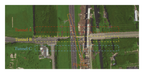
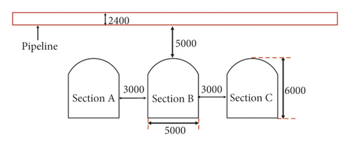
According to the geological survey report, the strata of the underground excavation section are mainly ④ sandy silt, ⑤ clay, and ⑥ silty clay. During the construction process, it is easy to collapse and experience local instability of the initial supporting structure. The parameters of the strata are shown in Table 1.
| Soil types | Depth (m) | γ (kN/m3) | с (MPa) | φ (°) | ν | E (MPa) |
|---|---|---|---|---|---|---|
| ① Miscellaneous Fill | 1.78 | 16.3 | 10.1 | 8 | 0.35 | 5.3 |
| ②Silty clay | 2.55 | 19.2 | 31.2 | 26 | 0.3 | 6.2 |
| ③Clay | 2.32 | 20.7 | 46 | 16 | 0.31 | 21 |
| ④Sandy silt | 2.31 | 22.1 | 9.2 | 19 | 0.28 | 16 |
| ⑤Clay | 2.61 | 48 | 47.2 | 16 | 0.31 | 21 |
| ⑥Silty clay | 12.35 | 20.5 | 33.1 | 24 | 0.3 | 6.2 |
3. Optimization Analysis of the Tunnel Construction Scheme
The tunnel excavation method has a greater impact on the deformation of the underground pipeline, especially because there are three tunnels in this project, which has a large section, so the selection of the excavation method is particularly important. Combining the actual situation of the project, the stability of the large-diameter pipeline, which is crossed beneath by the multihole shallow buried tunnel, is calculated and analyzed by the MIDAS GTS finite element software to obtain the influence of the tunnel construction scheme on the pipeline deformation. The three tunnel construction plans are shown in Table 2.
| Constructions schemes | Sequence of construction |
|---|---|
| 1 | A section ⟶B section ⟶C section |
| 2 | B section ⟶A and C sections |
| 3 | A and C sections ⟶B section |
Taking into account the influence of the model boundary conditions on the calculation results, the dimensions are 500 m in the x-direction, 400 m in the y-direction, and 30 m in the z-direction. The stratum, tunnel, pipeline, and grouting reinforcement are modeled by solid elements, the tunnel support is simulated by shell elements, the soil layer is modeled by Mohr–Coulomb, the tunnel structure is modeled by elastomer, and the boundary of the top surface of the model is set as a free boundary. Fixed constraints are set on the surrounding boundary and the bottom boundary. The formation parameters are shown in Table 1, the pipeline parameters are shown in Table 3, and the overall model diagram is shown in Figure 3. The different excavation steps are shown in Figure 4.
| Structure name | Diameter (mm) | γ (kN/m3) | E (GPa) | v |
|---|---|---|---|---|
| Pipeline | 2200 | 25 | 30 | 0.2 |
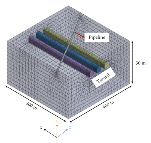
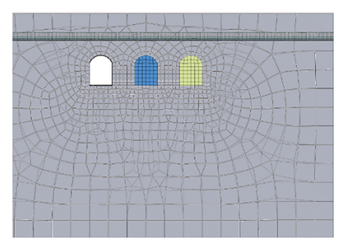
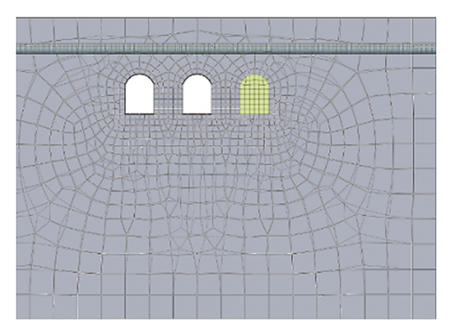
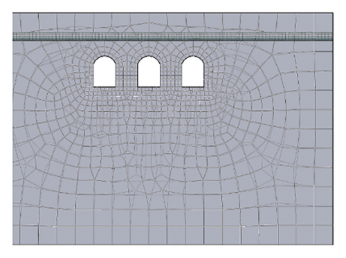
Scheme one: the order of construction is from left to right, namely, construct section A first, then construct section B, and finally construct section C.
The displacement cloud of the pipeline displacement in the first scheme is shown in Figure 5. Figure 5 shows that the maximum settlement of the pipeline is approximately 45.5 mm, and the differential settlement at both ends of the pipeline is approximately 11 mm. This is mainly due to unloading after the tunnel excavation, which causes the redistribution of stress and causes a certain amount of settlement in the upper strata and thus leads to the deformation of the pipeline, but because of the different excavation sequence, both ends of the pipeline will have differential settlement.
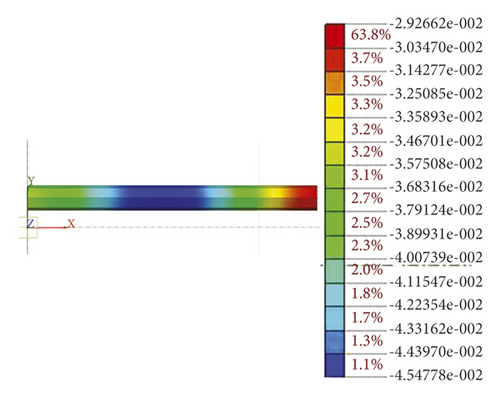
The displacement cloud of the pipeline displacement in the second scheme is shown in Figure 6. It can be seen from the displacement cloud diagram that the maximum deformation of the pipeline is approximately 36.6 mm, and the differential settlement at both ends of the pipeline is approximately 13 mm. Compared with the previous excavation sequence, the maximum deformation of the pipeline has been reduced by 8.9 mm, but the differential settlement at both ends of the pipeline has increased by 2 mm.
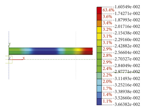
The displacement cloud of the pipeline displacement in the third scheme is shown in Figure 7. The maximum deformation of the pipeline is approximately 35.5 mm, and the differential settlement at both ends of the pipeline is approximately 10 mm. Compared with the above two excavation sequences, it can be found that the pipeline deformation caused by the current excavation sequence is moderate. At the same time, the differential settlement value at both ends of the pipeline is the smallest, indicating that the pipeline itself suffers the least disturbance.
Scheme comparisons are shown in Table 4. Table 4 shows that the pipeline settlement caused by the first scheme is the largest, and the second scheme is the smallest. However, the settlement difference of the pipeline in the second and third schemes is only 1.1 mm, the differential settlement at both ends of the pipeline caused by the second scheme is the largest, and the construction period is also considered. After comprehensive consideration, the third scheme was selected as the construction sequence for this project.
| Construction scheme | Maximum settlement of pipeline (mm) | Differential settlement on both sides of pipeline (mm) | Construction period |
|---|---|---|---|
| 1 | 45.5 | 11 | Longer |
| 2 | 36.6 | 13 | Moderate |
| 3 | 35.5 | 10 | Moderate |
4. Research on the Prereinforcement Scheme of Advanced Deep-Hole Grouting under Shallow Excavation
On the basis of the second section, the third scheme was selected and combined with the requirements of this project, and the range of deep-hole grouting was simulated. The soil parameters after grouting are listed in Table 5. In addition, find a construction plan that can not only meet the construction requirements but also reduce the project cost, which can further guide the construction.
| γ (kN/m3) | c (kPa) | φ (°) | E (MPa) | Ν |
|---|---|---|---|---|
| 2100 | 40 | 35 | 80 | 0.3 |
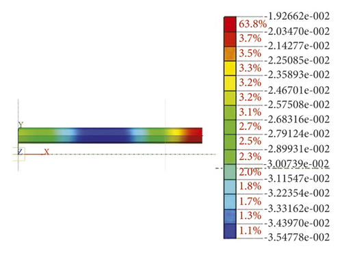
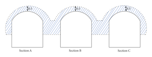
The first scheme: the soil is reinforced within 0.1 d (0.5 m) above the arching line, and the reinforced section is shown in Figure 8.
The displacement cloud of the pipeline displacement in the first scheme is shown in Figure 9. The maximum settlement of the pipeline is approximately 35.3 mm, and the differential settlement at both ends of the pipeline is approximately 13 mm. Compared with Figure 7, the maximum settlement values of the pipeline are similar, it shows that the first reinforcement scheme is not effective in controlling settlement.
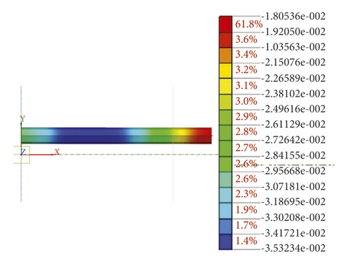
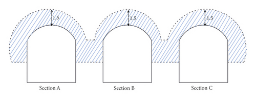
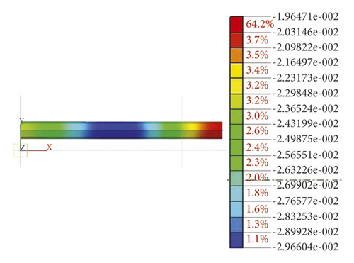
The second scheme: the soil is reinforced within 0.3 d (1.5 m) above the arch line, and the reinforced section is shown in Figure 10.
The displacement cloud of the pipeline displacement in the second scheme is shown in Figure 11. The maximum settlement of the pipeline is approximately 29.7 mm, and the differential settlement at both ends of the pipeline is approximately 6 mm. Compared with Figure 9, the settlement value of the pipeline in the first reinforcement scheme is smaller than that in the second reinforcement scheme, indicating that increasing the grouting range can effectively control the pipeline settlement.
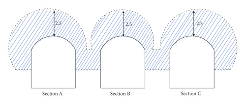
The third scheme: the soil is reinforced within 0.5 d (2.5 m) above the arch line, and the reinforced section is shown in Figure 12.
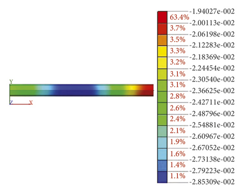
The displacement cloud of the pipeline displacement in the third scheme is shown in Figure 13. The maximum settlement of the pipeline is approximately 28.5 mm, and the differential settlement at both ends of the pipeline is approximately 4 mm. Compared with Figure 11, the settlement value of the pipeline in the third reinforcement scheme is smaller than that in the second reinforcement scheme, but the difference in value is only 1.2 mm, indicating that the third grouting reinforcement scheme can further control the settlement of the pipeline. However, the effect of controlling the pipeline settlement is not obvious.
The calculation results of the model are shown in Table 6. Table 6 shows that the pipeline deformation in Scheme 1 is the largest, with a value of 35.3 mm, which is close to the allowable specification value (35 mm). Therefore, the solution does not meet the requirements; although the maximum pipeline deformation in scheme 3 is the smallest, the difference between the pipeline and scheme 2 is only 1 mm, and considering the difficulty of construction and the cost of the project, scheme 2 is more cost-effective, so scheme 2 is selected as the final project construction plan.
| Grouting schemes | Reinforcement range (m) | Maximum settlement of pipeline (mm) |
|---|---|---|
| 1 | 0.5 | 35.3 |
| 2 | 1.5 | 29.6 |
| 3 | 2.5 | 28.5 |
5. Actual Monitoring Data Analysis
According to the above analysis, in the actual project, deep-hole grouting reinforcement is carried out on both sides of the tunnel, the reinforcement range is 1.5 m above the arch line, and then underground excavation is carried out. The above construction steps are carried out alternately. Until the tunnel is completed, the middle tunnel is finally excavated. The construction process is the same as that on both sides.
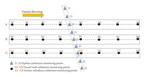
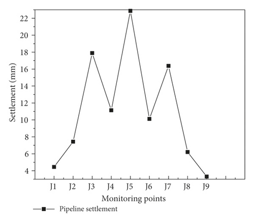
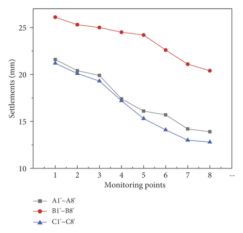
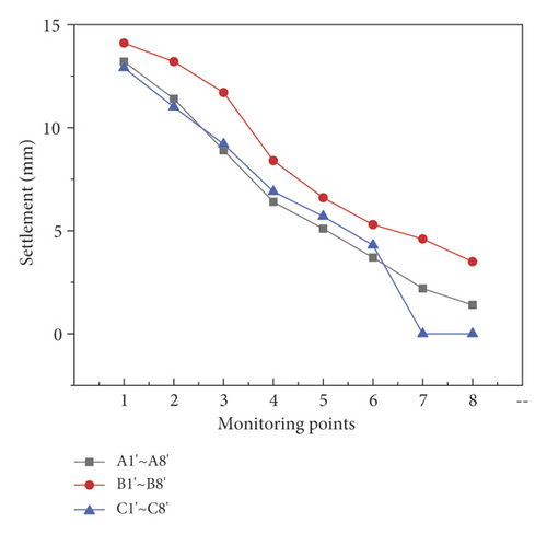
There are three rows of monitoring points, which are used to monitor surface subsidence and tunnel vault subsidence, arranged in the direction of the centerline of the digging section. A total of 48, such as point A1', are directly above point A1. There are nine pipeline settlement monitoring points, which are distributed along the pipeline through boreholes. The layout of the measuring points is shown in Figure 14.
5.1. Pipeline Settlement
Figure 15 shows that the settlement value of monitoring point J5 is the largest because it is affected by the superposition of three tunnel excavations. The final settlement value is approximately 23 mm, which is smaller than the result of the numerical simulation (29.6 mm). The main reason may be that there are various uncertain factors during the actual construction. For example, there will be certain errors in the quality of the slurry and the scope of grouting that will cause a difference between the monitoring value and the simulated value of the pipeline, but the settlement meets the requirements of the construction regulations (35 mm).
5.2. Tunnel Vault Subsidence
Figure 16 shows that the settlement value of the tunnel vault along the direction of undercutting gradually decreases. The maximum settlement values of the three tunnels are 21.6 mm (A1), 26.1 mm (B1), and 21.2 mm (C1), and the settlement value at point B1 is the largest because the settlement at this point is affected by the excavation of the three tunnels, which coincides with the settlement law of the pipeline.
5.3. Surface Subsidence
Figure 17 shows that the settlement value of the ground surface gradually decreases along the direction of the undercut. The maximum settlement value of the ground surface above the three tunnels is 13.2 (A1'), 14.1 (B1'), and 12.9 (C1'), and the settlement value of point B1' is the largest because the settlement of this point is affected by the excavation of the three tunnels, which is consistent with the settlement law of the pipeline and the tunnel vault. At the same time, due to the self-stabilizing ability of the soil, the surface settlement value at the same vertical position is smaller than that of the tunnel vault. Monitoring points C7' and C8' did not collect relevant data due to the failure of the monitoring equipment.
6. Conclusions
- (1)
According to the numerical simulation results, it can be found that different tunnel excavation sequences will cause the deformation of the pipeline in the upper soil, but the magnitude of the deformation is different. The excavation method, which constructs the tunnels on both sides at the same time and then constructs the middle tunnel, not only increases the excavation speed but also controls the pipeline deformation better than the other two schemes, especially in terms of differential settlement on both sides of the pipeline.
- (2)
By studying the relationship between the grouting reinforcement range and the vertical distance between the new tunnel and the existing pipeline, it is found that when the deep-hole grouting range is approximately 0.1d above the arch line, the pipeline deformation during tunnel excavation is large. When the reinforcement range is 0.5 d, the pipeline deformation is minimal, but the difference between scheme 2 and scheme 3 is small, and many other factors need to be considered, such as project cost and actual construction difficulty; thus, it is more reasonable to choose a reinforcement range of 0.3 d in scheme 2.
- (3)
The actual monitoring data show that the cumulative settlement value of the ground surface and pipeline gradually increases, and the final settlement values are 14.1 mm and 23 mm, respectively, which are less than the 30 mm and 35 mm required in the specification, indicating that the excavation plan and grouting method proposed in this paper are feasible, which can provide references for similar projects in the future.
Conflicts of Interest
The authors declare that they have no conflicts of interest.
Acknowledgments
The work presented in this paper was supported by the Project of State Key Laboratory of Geotechnical Mechanics and Engineering (no. Z019018) and the Regional Joint Fund of Guangdong Basic and Applied Basic Research Fund (no. 2019A1515110836).
Open Research
Data Availability
The numerical and measurement data used to support the findings of this study are included within the article.


