Physical Modeling of a Shallow-Buried Metro Tunnel in the Soft Loess Layer Using Similarity Theory
Abstract
The special engineering characteristics of loess will inevitably bring hidden trouble to the construction of shallow buried subway tunnel. The purpose of this paper is to investigate the variation law of surrounding rock stress, lining stress, and surface settlement in loess tunnel construction and further explore the optimum construction method in the soft loess area. A model test considering the different excavation methods and prereinforcement measures was conducted to measure the surrounding rock pressure, lining stress, and surface settlement under different working conditions. The results show that the sequence of tunnel excavation had a great influence on the stability of the tunnel. As the experimental steps increased, the surrounding rock stress and lining stress at each monitoring section gradually increase. Especially, stress concentration could easily occur at the arch foot of the tunnel. The pre-reinforcement measure, especially the WSS grouting, was more crucial than the excavation method. Considering the number of elements, the combination of DSDM excavation method and WSS grouting reinforcement method was proposed as the final construction method of the tunnel in soft loess area in this paper. The research results can effectively guide the design and construction of a shallow tunnel in the soft loess area.
1. Introduction
With the rapid development of urbanization, traffic congestion has become a momentous factor restricting the development of urban economy. The development and utilization of urban underground space can effectively address this problem. When the underground space is excavated, it will inevitably affect the safety of surface buildings, and even lead to collapse of ground or buildings, especially in the soft loess area with complex geological conditions, which brings severe challenges to the urban underground rail construction of cities in western China. Loess is a special soil with low strength, large pore diameter, and strong collapsibility, which often brings different degrees of influence to the metro tunnel construction [1–4]. With the development of urban underground rail transit construction, the research of a metro tunnel in the loess region has gradually become the focus of researchers [5–11] studying the deformation and settlement of surface structures caused by shield tunneling through the ancient city wall by combining numerical simulation and field test. Li et al. [12] analyzed the application of three-bench seven-step excavation method in a loess tunnel through numerical simulation and on-site monitoring. Shao et al. [13] put forward the deformation calculation method of collapsible loess foundation from the theoretical point of view. Zhang et al. [14] analyzed the possible factors causing loess tunnel collapse and found that the excavation method has the greatest impact on the stability of the tunnel. Qiu et al. [15] analyzed the tunnel structure response and surface response in a water-rich environment based on water gushing phenomenon in the loess metro tunnel. Liu and Lai [16] summarized the load distribution characteristics on the secondary lining. Xue et al. [17] studied the influence of the relative physical parameters on the stability of loess tunnel. Li et al. [18] carried out an in-situ immersion test on the construction site of a large thickness collapsible loess tunnel to discuss the influence mechanism of stratum subsidence on the tunnel lining structure. The abovementioned research studies on collapsible loess mainly focus on the highway tunnels engineering and the tunnel structural safety, which lay a commendable foundation for further research in the field. Nevertheless, there are few related research studies on the safety of subway tunnels under existing railways. In view of the abovementioned problems, the actual construction mainly exists in the following two aspects. On the one hand, the unloading action caused by underpass tunnel excavation in the actual project is easy to induce the uneven differential settlement of the surface subway lines, which seriously affects the operation safety of the existing railway. On the other hand, the loess stratum often has significant subsidence deformation under the influence of flooding, which will have a certain degree of influence on tunnel structure and surface railway. Hence, it is necessary to study the construction technology of the tunnel in the soft loess region.
There are many factors that induce surrounding rock deformation and stratum settlement, among which the more important factors are the excavation depth, section size, excavation method, and pre-reinforcement measures, especially shallow tunnel. Some scholars carried out research studies from the direction of theoretical research. Mair and Taylor [19] first reported the method of using simple plastic solution to predict foundation deformation and pore pressure changes caused by tunnel excavation. Mo and Yu [20] introduced the CASM model into the cavity contraction theory, so as to simulate the mechanical response of soil around the tunnel caused by excavation. Wang et al. [21] conducted a new two-dimensional model of settlement propagation based on the random medium theory to clarify the propagation law of soil settlement caused by tunnel excavation. Lyu et al. [22] proposed a theoretical analysis to calculate the stress distribution of the shallow-buried twin-tunnel around the layered stratum. In terms of numerical simulation, Sterpi and Cividini [23] studied the failure behavior of shallow underground roadway is discussed through model tests and finite element simulation. Kasper and Meschke [24] presented a three-dimensional finite element simulation model for shield-driven tunnel excavation. However, due to the limitation of finite element itself, the accuracy of simulation in actual engineering fluctuates greatly. Considering that the discrete element method (DEM) has some advantages in describing the instability and large deformation of rock mass, some scholars had carried out research studies on it and achieved some results [25–28]. In a field test, Bian et al. [29] conducted a long-term on-site monitoring of the Huangjiazhai tunnel during tunneling in order to analyze the formation mechanism of large soft rock deformation. Fu et al. [30] the effects on ground and adjacent buildings when tunneling through completely weathered granite debris based on field test. Although field monitoring can accurately determine the change law of physical parameters of tunnels, it usually requires long-term monitoring and high cost, which restricts its development to a certain extent. A physical model test is a common geotechnical test method, which has been widely used in tunnel analysis [31–37] indicated the stress and strain states of loess can be replicated by building the physical model on a proper scale. Yang et al. [38] used the physical modeling test to study the excavation stability of inclined upper soft and lower hard stratum tunnel. Song et al. [39] studied the deformation evolution laws, cracking mechanism, and failure process of the secondary lining for an existing highway tunnel in loess ground by carrying out laboratory model tests. Weng et al. [40] studied the influence of loess collapsibility on the stability of the subway tunnel under different water immersion conditions. Xu et al. [41] conducted a model test to investigate the relationship between collapse failure and longitudinal topography of loess tunnel construction and to further discuss the influence of slope angle and excavation direction on the terrain. The abovementioned research results have promoted the development of tunnel model test to a certain extent. However, there are few studies on the stability and safety of the special project in soft loess area, such as going through existing railway engineering by the metro tunnel. Although there are many existing methods of shallow underground excavation and pre-reinforcement of the stratum, its applicability to the special project that the subway tunnel goes through the existing railway in soft loess area remains to be studied.
In this paper, a shallow tunnel model of using the similarity theory of the tunnel engineering of Xi’an Metro Line 4 was designed to explore the evolution law of surrounding rock stress, lining stress, and surface settlement during tunnel excavation. Furthermore, the optimum tunnel excavation methods and pre-reinforcement measure were discussed which provides technical support for the construction of the shallow tunnel in the soft loess area. In particular, it can be applied to provide references for tunnel excavation, foundation reinforcement, and other related engineering construction in soft loess area.
2. Background and Geotechnical Investigation
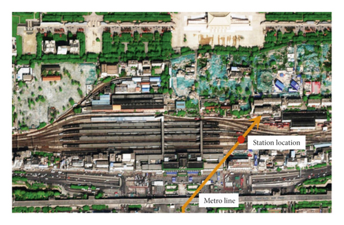
The engineering site was the shallow of tunnel Xi’an Metro Line 4, which is located in the Xi’an City, Shaanxi Province. The tunnel is the length of 34.34 km and passes through 28 stations. The construction of the national railway station as the project control project is the most difficult. In this paper, the research and analysis are mainly carried out on the tunnel under the national railway section. Figure 1 shows where the project is located. The left and right line tunnel length passing through 20 and 15 tracks are 240.85 m and 256.3 m, respectively. The tunnel is a separate double tunnel with a buried depth of 10.5 m, whose equivalent radius is 5.5 m and the distance of midline is 54.5 m. The main direction of the tunnel is north-south, oblique to Xi’an national railway Station about 53°. In addition, composite lining is determined as the support method in the project. This is not only the first shallow-buried tunnel project under the core area of railway station in China but also the first tunnel project in the world that has adverse effects on so many tracks. As the control engineering of the project, there are the following difficulties in the construction of the tunnel under the railway station: (1) it is a large-span tunnel with maximum cross section of about 11.70 m. (2) The loess near the groundwater level is prone to collapse in case of water, which brings severe challenges to the construction. (3) The groundwater level is located at 5.3∼6.2 m, higher than the construction area. (4) The ground track settlement caused by construction cannot exceed 15 mm.
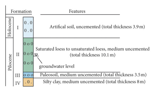
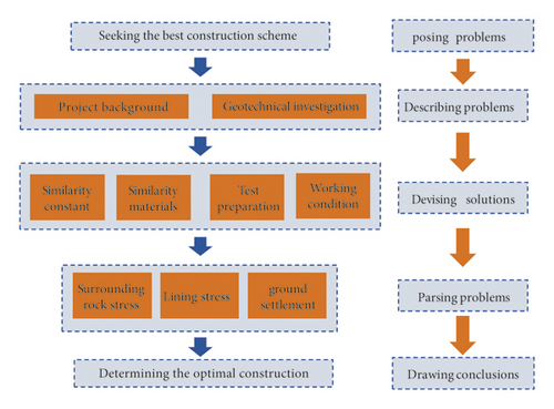
The geological condition of the tunnel excavation area belongs to the typical loess landform. Based on the geological survey and drilling exploration, the excavation area in the excavation area can be roughly divided into the artificial soil layer, loess layer, and paleosoil layer and silty clay layer based on the influence of sedimentary environment in Figure 2. The groundwater level is located in the loess layer, which shows flow plasticity and high compressibility after saturation. In this complex stratum condition, the construction of large section shallow-buried tunnel is risky extremely. In order to have a clearer exhibiting of the research strategies of this paper, Figure 3 shows the research flowchart of this paper.
3. Design of the Physical Model Test
3.1. Similarity Constant
In order to ensure that the conclusion of the model test can precisely clarify the deformation and stress characteristics of the prototype, the similarity theory shows that the geometric and physical parameters in the model test must be similar to the corresponding prototype parameters. C is the similarity constant. The physical quantities included in this paper are shown in Table 1. To accurately reflect and simulate the mechanical characteristics and deformation of surrounding rock, the geometry similarity ratio between the prototype model and model was determined as CL = 15. The similarity ratio of bulk density was taken model test as Cγ = 1. Furthermore, the similarity ratio of other physical quantities could be obtained by combining CL, Cγ, and the similarity conditions obtained by the three basic theorems of similarity theory.
| Physical quantities | Symbol | Similarity ratio | Dimension |
|---|---|---|---|
| Geometry | L | CL = 15 | [L] |
| Bulk density | γ | Cγ = 1 | [M · L − 2 · T − 2] |
| Stress | σ | Cσ = 15 | [M · L − 1 · T − 2] |
| Strain | ε | Cε = 1 | 1 |
| Displacement | δ | Cδ = 15 | [L] |
| Elastic modulus | E | CE = 15 | [M · L − 1 · T − 2] |
| Poisson’s ratio | μ | Cμ = 1 | 1 |
| Cohesion | c | Cc = 15 | [M · L − 1 · T − 2] |
| Friction angle | φ | Cφ = 1 | 1 |
| Compressive strength | R | CR = 15 | [M · L − 1 · T − 2] |
3.2. Similar Materials of the Model
The soil similar materials were determined according to the physical parameters of natural soils in-site of the project. The soil layers with similar properties were grouped into one group to reduce the number of soil layers in the experiment. As a consequence, the in-suit soil layers were divided two layers. In order to determine the soil material materials of the model, γ, μ, c, φ, and E were selected as the control indexes in the test. Loess, clay, sand, water, mineral butter, and wood chips were selected as initial materials in the experiment, and model materials were finally obtained through a lot of orthogonal experiments. Table 2 shows the physical parameters of soils, which shows that the soil materials meet the model test requirements.
| Category | Bulk density | Poisson’s ratio | Cohesion | Friction angle | Elastic modulus |
|---|---|---|---|---|---|
| γ(kN/m3) | μ | c(kPa) | φ (°) | E(MPa) | |
| Prototype | 18.0 | 0.38 | 24.0 | 14.5 | 12.5 |
| 20.0 | 0.33 | 31.7 | 17.2 | 40.3 | |
| Model | 17.3 | 0.37 | 1.55 | 14.2 | 0.9 |
| 19.8 | 0.31 | 2.10 | 16.8 | 3.0 | |
Similar to the model soil materials, the determination of tunnel lining materials also depends on the field measured physical parameters of them. The elastic modulus of primary support and secondary lining of the project were 20–28 GPa and 25–38 GPa, respectively. Poisson’s ratio was 0.2. The construction sequence was the secondary lining pouring after the initial support transfixion in the actual construction process. To ensure that the stress release of tunnel excavation is consistent with the prototype, the model only considered the influence of the primary support. It is noted that the lining mentioned below refers to the initial support. The control index of lining in the model was elastic modulus. Based on the elastic modulus as the control parameter of lining material in the model, gypsum, water, and barite powder were selected as initial materials through a series of orthogonal tests, and the appropriate material ratio was obtained. Table 3 shows the tunnel lining physical parameters for the model and prototype.
| Category | Strength | Poisson’s ratio | Cohesion | Friction angle | Elastic modulus |
|---|---|---|---|---|---|
| R(GPa) | μ | c(kPa) | φ (°) | E(GPa) | |
| Prototype | 33 | 0.2 | 2200 | 55 | 20.0 |
| Model | 2.26 | 0.2 | 2200 | 55 | 1.33 |
The stratum to be excavated must be pre-reinforced to weaken the influence of excavation on the stratum and the track above in the construction process. The prelining reinforcement and double pipe nonshrinkage grouting (WSS grouting) reinforcement as two kinds of advance reinforcement measures were adopted in the physical model test. WSS grouting reinforcement area at upper section of the tunnel 150°, and the outer lining 0.13 m used the mixed material of concrete and the second layer surrounding rock to simulate. When the mass ratio of concrete and the second soil layer was 1 : 9.8, the model parameters satisfied the similarity ratio. By contrast, the prelining reinforcement region at arched outer lining 0.02 m adopted the mass ratio of concrete and the second soil layer was 1 : 3.5. In addition, the above pre-reinforcement measures were completed by compacting the soil during filling the soil layer. In particular, the compressive strength of the reinforcement area was selected as the control index for the ratio of the abovementioned materials based on engineering experience. The compressive strengths of prelining reinforcement region and WSS grouting reinforcement region in the prototype were 9.6 GPa and 1.8 GPa, respectively, while the compressive strengths of the model obtained by the above material ratio were 0.64 GPa and 0.12 GPa. It can be seen that the materials of pre-reinforcement region of the model primarily fit the model need.
3.3. Test Preparation
The size of the model box, shown in Figure 4(a), used in this test is 320 cm long, 60 cm wide and 200 cm high. The front and back of the model box were made of a 10 mm thick transparent toughened glass to observe the deformation of the tunnel. Moreover, a hole was cut in the transparent toughened glass in front of the model box, which is equal to the size of model tunnel section. It is worth mentioning that because the influence width of the settlement groove is less than the distance between the middle line of the two tunnels [42] the model test was carried out with a single tunnel. Therefore, the model box can meet the experimental requirements.
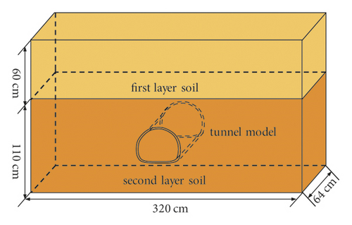
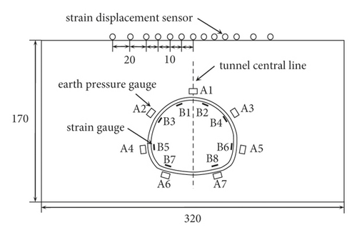
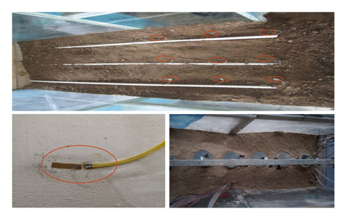
In the model test, the surrounding rock stress was monitored by the strain type earth pressure gauge. This paper selected the middle of the tunnel for monitoring the cross-section to reduce the influence of size effect. The seven monitoring points were installed in the surrounding of tunnel, respectively. Except for one measuring point at the vault, two measuring points are arranged at the other positions. The resistance type strain gauge and static strain gauge were used for lining strain test. The layout of a strain gauge was similar to the layout of the earth pressure gauge. The difference was that it was attached to the lining model, whereas the earth pressure gauge was buried in the soil.
The surface settlement was measured by symmetrically distributed strain displacement sensor. The measure points above the tunnel center line were more concentrated to accurately reflect the law of surface settlement. The detail layout of the test components is shown in Figures 4(b) and 4(c).
The excavation methods used in the model test included two-step excavation method, cross diaphragm method (CRD), and double-side-drift method (DSDM). The pre-reinforcement forms adopted no reinforcement, prelining reinforcement, and WSS grouting method. In the model test, six conditions were designed considering the combination of different excavation and pre-reinforcement measures, so as to determine the optimum construction technology of shallow tunnel in soft loess area, as shown in Table 4.
| Working conditions | Excavation methods | Pre-reinforcement measures |
|---|---|---|
| Working condition 1 | Two-step method | No reinforcement |
| Working condition 2 | CRD-4 method | No reinforcement |
| Working condition 3 | CRD-4 method | WSS grouting reinforcement |
| Working condition 4 | CRD-4 method | Prelining reinforcement |
| Working condition 5 | CRD-6 method | No reinforcement |
| Working condition 6 | DSDM method | WSS grouting reinforcement |
3.4. Detail Excavation Process
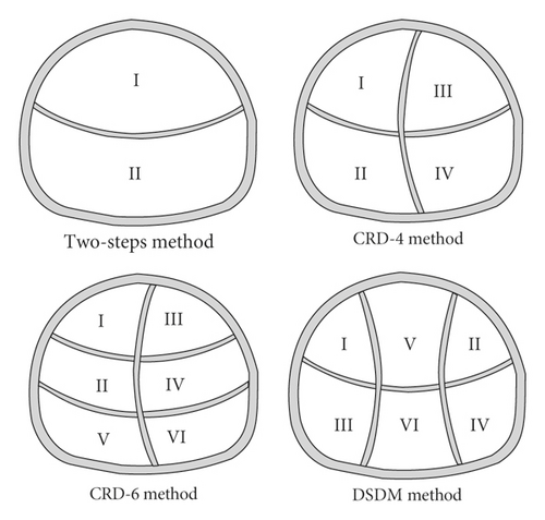
To truly and accurately reflect the mechanical form during the actual construction, the excavation scheme of the simulation was similar to that of the actual construction site. In this test, the Luoyang shove was used to slowly excavate the tunnel to prevent over- and under-excavation. The detail excavation sequences of different excavation methods are shown in Figure 5. The excavation step length of all the above excavation methods was 0.2 m. In addition, the previous procedure leaded the next procedure by one step length to form steps in above excavation methods. The two-step excavation was carried out from top to bottom. The CRD method followed the excavation method from left to right and from top to bottom. The DSDM method adopted the procedure from two sides to middle and from top to bottom. The testing data were recorded once for each excavation. It is worth noting that due to the small operability of the reserved core soil in the test, the reserved core soil was no longer simulated in the CRD method and only the influence of space release on the surface settlement was considered.
4. Results and Discussion
4.1. Stress Law of Surrounding Rock
4.1.1. Influence of Different Excavation Measures on Surrounding Rock Stress Change
Two steps, CRD-4 and CRD-6 (conditions 1, 2, and 5), were taken as a group to explore the overall stress distribution of tunnel surrounding rock in the soft loess area without pre-reinforcement, as shown in Figure 6. The stress of surrounding rock at each measuring point is basically proportional to the number of excavation steps. The surrounding rock grew rapidly at the initial stage of excavation. However, when the surrounding rock stress increases to a certain extent, the growth rate would not be significant. Specifically, the surrounding rock of tunnel was disturbed at different degrees in the process of tunnel excavation and its variation was affected by the degree of disturbance. For example, the positions most affected by the first step excavation were the vault and the left arch shoulder in the CRD-4 excavation method, whose corresponding confining pressures were 2.6 kPa, which were much higher than other parts of the tunnel as shown in Figure 5(b). In particular, the surrounding rock stress on the left and right sides of the two-step method showed obvious symmetry, while the data of CRD-4 and CRD-6 excavation methods were of poor symmetry, which is also caused by the reason. In addition, the surrounding rock stresses at different locations during tunnel excavation generally satisfied vault and arch shoulder > arch bottom and arch foot.
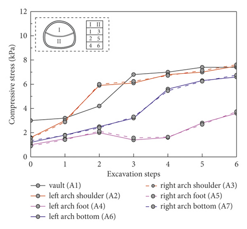
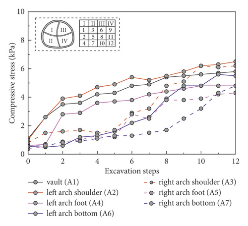
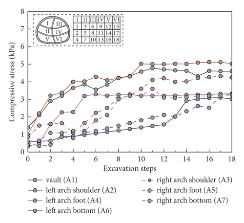
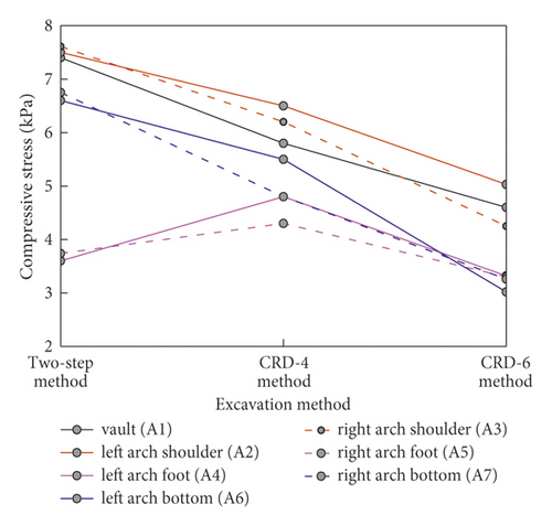
Figure 7 shows the final surrounding rock stress under different excavation method without pre-reinforcement. Except for the measuring point at the arch foot, the surrounding rock stress at other measuring points was as follows: two-step method > CRD-4 > CRD-6. This indicated that the increase of excavation section can significantly reduce the disturbance of surrounding rock. In addition, the stress release of surrounding rock can be further controlled. In particular, the stress at the arch foot of the two-step method is lower than that at CRD-4. The surrounding rock at the arch foot and the arch bottom were excavated at the same time during two-step excavation, so more stress was released at the arch bottom, while the stress at the vault position was less.
4.1.2. Influence of Different Pre-Reinforcement Measures on Surrounding Rock Stress Change
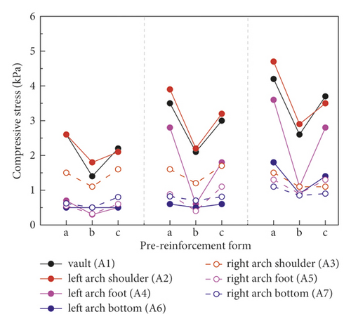
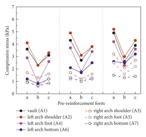
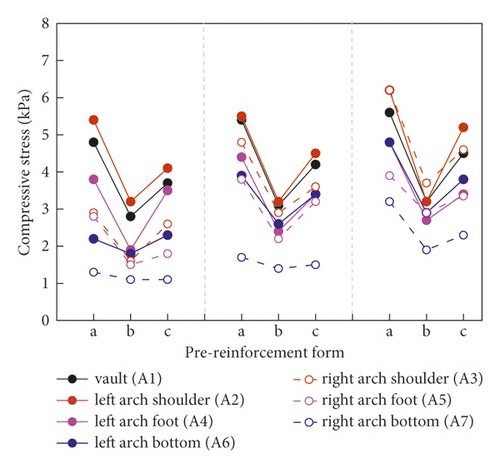
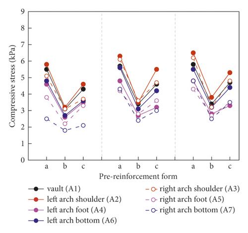
Figure 8 shows the change of the surrounding rock stress adopting CRD-4 excavation method to further analyze the influence of pre-reinforcement forms on surrounding rock stability. The parts a, b, and c in Figure 7 represent no reinforcement, prelining reinforcement, and WSS reinforcement, respectively. With the step sequence of each excavation section, the overall trend of surrounding rock stress was still increasing under the three working conditions. At the same time, the growth trend gradually slowed down with the excavation section gradually through. More importantly, the surrounding rock stress variation of the CRD-4 excavation method under different pre-reinforcement forms presented the same law. When the surrounding rock was excavated after pre-reinforcement, the surrounding rock stress was significantly reduced compared with that without pre-reinforcement. Compared with surrounding rock stress variation under the two kinds of pre-reinforcement forms, the prelining reinforcement measures can more availably limit the deformation of surrounding rock. The above conclusion can provide reasonable references for the surrounding rock control in the construction process of soft loess area in the future. In addition, the surrounding rock stress distribution range of each measuring point was wide, while the distribution of the measuring point was gradually concentrated with the excavation section increasing. It further indicated that the surrounding rock stress was released and stress redistribution occurred at the initial excavation. The stress redistribution was basically completed at the end of excavation. Therefore, the primary support can availably limit the stress of surrounding rock in the construction.
4.1.3. Influence of Different Excavation Methods on Surrounding Rock Stress Change (Pre-Reinforcement Method)
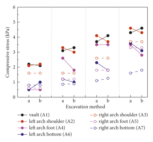
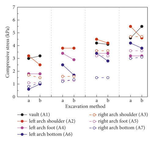
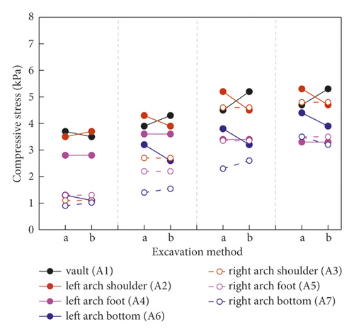
Figure 9 analyzes the influence of excavation method on surrounding rock stress distribution adopting WSS grouting reinforcement. The surrounding rock stress at each measurement point gradually increased with the sequence of excavation section increasing in the same excavation section. By comparing two different excavation methods, the surrounding rock stress distribution of them is basically the same. In other words, both the CRD-4 method and DSDM method can well solve the problem of controlling the surrounding rock deformation. Besides, the stress release of surrounding rock under six working conditions was statistically analyzed, as shown in Table 5. The ratios of final stress and initial stress of CRD-4 method and DSDM method were 4.40 and 4.11. It is further proved that the pre-reinforcement region and excavation method have great impact on the variation of surrounding rock stress. In particular, the two-step method has the minimum stress release ratio of surrounding rock in Table 5. Because the step sequence of the two-step method was less, the stress redistribution of the surrounding rock was still going on when the excavation finished. It is the dominant reason that the surrounding rock stress release ratio of the two-step method was the smallest.
| Working condition | Condition 1 | Condition 2 | Condition 3 | Condition 4 | Condition 5 | Condition 6 |
|---|---|---|---|---|---|---|
| Final stress/initial stress | 3.69 | 7.36 | 4.40 | 4.13 | 5.52 | 4.11 |
4.2. Law of Lining Stress
4.2.1. Influence of Different Excavation Methods on Lining Stress Change
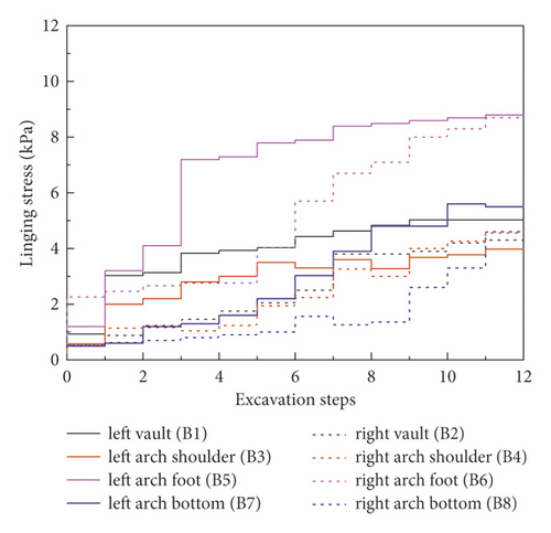
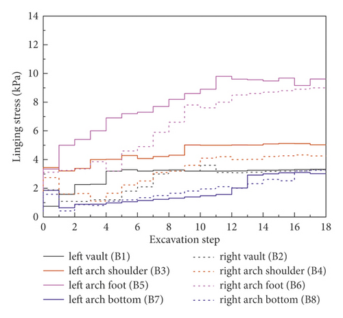
To study the real stress state of the lining in the actual metro tunnel, the stress of the lining in the process of excavation and unloading is deeply analyzed in this paper. The lining stress data was read per excavation step. Taking two working conditions 2 and 5 as an example, Figure 10 analyzes the lining stress variation law under different excavation methods. The lining stress began to increase, then decreased or tended to be stable gradually during tunnel excavating. In particular, compared the other measure points, the values of B5 and B7 were distinctly larger. Moreover, the variation rate of measuring points shows the follow laws: When the monitoring point is in the current excavation section, its stress variation rate increases significantly. Its variation rate is slower when the measuring point is far from the current excavation section. When the excavation of the current section is finished, the variation ratio gradually tends to be zero with the continuous excavation.
4.2.2. Influence of Different Pre-Reinforcement Measures on Lining Stress Change
As shown in Figure 11, the data from working conditions 2, 3, and 4 were analyzed for the lining stress variation laws of the different pre-reinforcement measures under the condition of the same excavation method (CRD-4 method). The lining stress in all measure points always increased prominently and then gradually stabilized under different pre-reinforcement measures. Especially, the stress at the invert arch tends to increase obviously, when the tunnel excavation process was completed. The lining stresses at each measuring points on the left positions were significantly higher than that at the same position on the right positions. In different pre-reinforcements, the overall variation of lining stress showed that the lining stress is the largest under the condition of no pre-reinforcement, followed by WSS grouting reinforcement, and the lining stress is the least under the condition of prelining reinforcement, which is more conducive to the stability of the tunnel. The largest surrounding rock stress increment is at the arch foot, and the peak value is about 8.79 kPa.
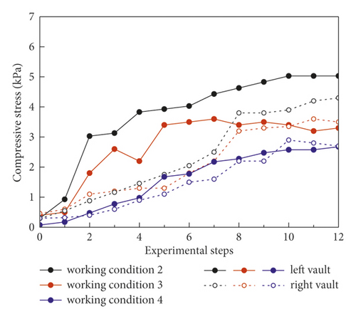
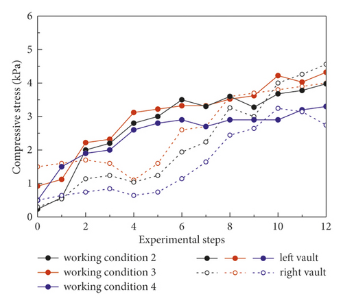
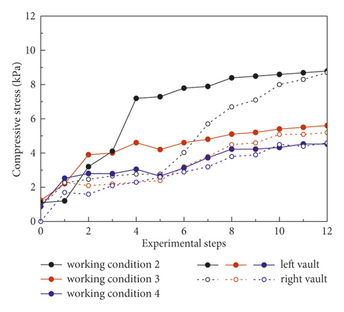
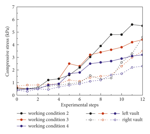
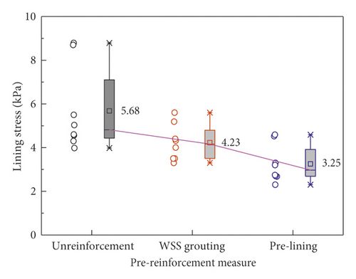
Figure 12 shows the ultimate lining stress data under various working conditions. When the pre-reinforcement measures changed, it shows that the lining stress increment at each measuring point of the same section was clear distinction. In addition, the mean lining stress under different pre-reinforcement measures (conditions 2, 3, and 4) was 5.68 kPa, 4.23 kPa, and 3.25 kPa, which shows that the lining stress decreases significantly after the preexcavated soil was strengthened in advance and the prelining measures is better at reducing lining stress than WSS grouting. Specifically, when the reinforcement measures changed from no reinforcement to WSS grouting, then from WSS grouting to prelining, the ultimate lining stress in the vault, the arch shoulder, the arch foot, and the arch bottom under the working conditions 3, 4, and 5 on the left of the tunnel was 5.03 kPa, 3.30 kPa, and 2.68 kPa, 4.32 kPa, 3.98kPa, and 3.30 kPa, 8.79 kPa, 5.60 kPa, and 4.52 kPa, and 5.50 kPa, 4.40 kPa, and 3.20 kPa, respectively. The lining stresses under conditions 3 and 4 were about 0.66 and 0.53; 0.92 and 0.76; 0.64 and 0.51; and 0.58 and 0.8 times of condition 2, respectively.
4.2.3. Influence of Excavation Method on Lining Stress Change (WSS Grouting Method)
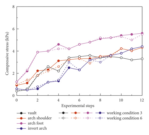
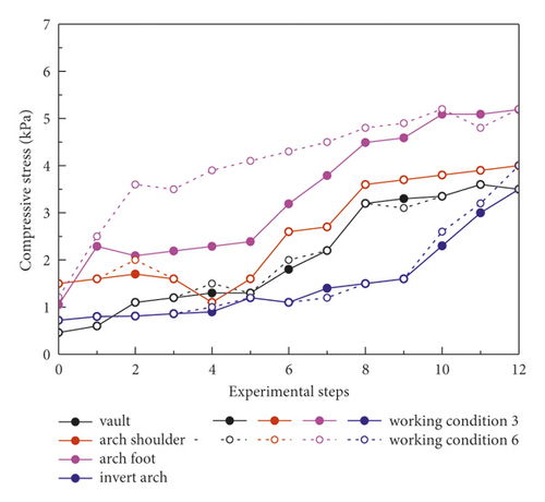
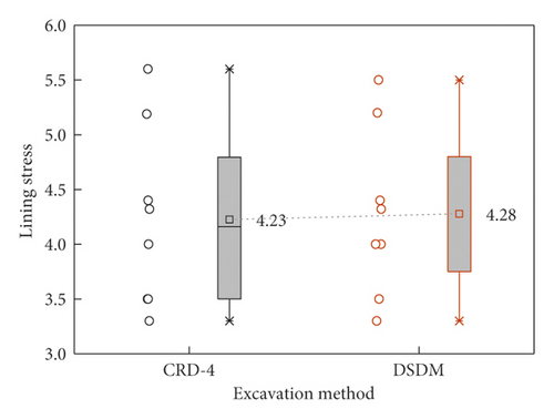
Figure 13 shows the lining stress monitoring result under different excavation methods under WSS grouting conditions. The lining stress gradually increased and eventually tended to be stable with tunnel excavating. In particular, the lining stress at the left and right arch feet increased more obviously than that at other measuring points. In addition, compared with the real-time variation of lining stress in the excavation process under the two excavation methods, the lining stress increment was almost the same. This indicates that CRD-4 and DSDM excavation methods have the same ability to reduce the lining stress under the premise of WSS grouting reinforcement. Figure 14 shows the ultimate lining stress at different measure points under working conditions 3 and 6. The mean ultimate lining stresses under working conditions 3 and 6 were 4.23 kPa and 4.28 kPa. This further indicates that both working conditions 3 and 6 can well control the deformation and loading condition of tunnel lining.
4.3. Displacement Law of Ground Settlement
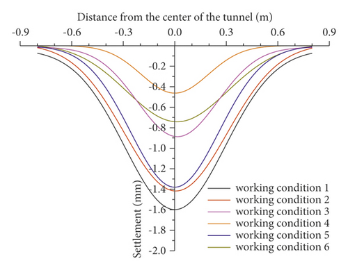
So as to analyze the variation law of surface settlement caused by tunnel excavation, 13 monitor points symmetrical along the tunnel center line were arranged on the surface above the tunnel. Figure 15 shows the distribution of surface subsidence under different working conditions. The results show that the surface settlement showed obvious subside. Moreover, the maximum surface settlement is at the vault. The peak values of surface settlement are 1.42 mm and 0.45 mm under all working conditions, respectively. By comparing the maximum settlement value under the condition that the soil is not reinforced in advance (working conditions 1, 2, and 5), it can be found that the settlement value of two-step method is the largest, followed by CRD-4 and CRD-6. This indicated that surface subsidence can be controlled to some extent by increasing the number of tunnel sections. Compared with the working conditions 3 and 4, the maximum settlement of the two are 0.87 mm and 0.45 mm, respectively. Therefore, the prelining reinforcement measure was superior to WSS grouting under the CRD-4 excavation method. Analogously, it can be seen that the DSDM method was superior to CRD-4 under WSS grouting reinforcement measure by comparing working conditions 3 and 6. In addition, it can be seen that it was more important to strengthen the soil in advance than the choice of excavation method in controlling the surface settlement.
5. Conclusion
- (1)
The excavation method has a significant effect on controlling the stress release of surrounding rock of the tunnel without advanced reinforcement treatment, the stress release of surrounding rock is significantly lower with the increase of excavated sections. At the same time, the stress release of surrounding rock near the tunnel face is the most significant, especially at the arch shoulder and vault.
- (2)
The excavation sequence has a significant effect on the lining stress characteristics in different parts of the tunnel, which shows that the lining stress in the part excavated first is more remarkable. In addition, the influence of tunnel excavation method on lining stress is no longer significant under the same advanced reinforcement condition.
- (3)
The pre-reinforcement measures can memorably improve the stability of the stratum. The prelining pre-reinforcement measure has better performance in controlling surrounding rock stress, lining stress, and surface settlement compared with the WSS grouting pre-reinforcement measure.
- (4)
The surface settlement presents a “V” distribution, and the peak value is located at the center line of the tunnel. In addition, pre-reinforcement measure was more crucial than the excavation method in controlling the surface settlement.
- (5)
The combination of DSDM excavation method and WSS grouting reinforcement method was proposed as the final construction method of tunnel in soft loess area in this paper, which can reasonably meet the engineering needs.
Conflicts of Interest
The authors declare that they have no conflicts of interest..
Acknowledgments
The authors acknowledge the financial support provided by the National Natural Science Foundation of China (U1934213).
Open Research
Data Availability
All data, model test photos, and codes generated or used during the study are included within the article.


