[Retracted] Dual Solution with Heat Transfer through Moving Porous Plate of an Unsteady Incompressible Viscous Fluid
Abstract
We examine graphically the behavior of the dual solution of an unsteady incompressible viscous flow with heat transfer due to a moving porous surface. The mathematical model is developed with the implementation of conservation laws which are then tackled numerically, and the simulations are performed through the Keller–Box technique. Application of the Keller–Box technique allows the non-linear differential equations to transform to a scheme of linear differential equations which are easier to illuminate. Outcomes of velocity and thermal behavior are shown graphically for certain values of the dimensionless parameters. It is obvious from the results that temperature of fluid decreases with the increasing values of dimensionless Prandtl number Pr, whereas the velocity enhances for blowing situations.
1. Introduction
Heat transfer properties and boundary layer flow through the contracting sheet include numerous implementations of the engineering system. Many fluids are involved in industries, especially in the metallurgy wrapping processes. These fluids are mostly non-Newtonian in nature. Some of these types of fluids include Casson fluid, Williamson fluid, Maxwell fluid, and so on. Many authors in their work have especially considered the non-Newtonian fluids to discuss the unwinding properties of fluid models. For these liquids, the framework is to demonstrate the nature of their viscoelastic behavior. The flow of viscous fluid is illustrated by Navier–Stokes equations. Equations describing highly non-linear partial differential equations (PDEs) with exact solutions [1] exist in some extraordinary circumstances. The solution of boundary layer flow over a continuously moving surface was discussed by Sakiadis [2]. Heat transfer is an important factor when dealing with boundary layers on moving surfaces [3]. The analytical solution of boundary layer flow by using linearly stretching sheet was achieved [4]. The 2-dimensional flow near a stagnation point was first presented [5]. Some more recent works on different flow geometries and scenarios are reported in [6–9].
During the flow of an incompressible viscous fluid, differentiation of the boundary layer has been actively considered [10]. Ma et al. [11] studied the non-porous plate’s unsteady separation stagnation point flow. In these studies, it was also discussed how the incompressible viscous fluid behaves for stretching/shrinking. This investigation was then extended by Mahapatra et al. [12] to incorporate the MHD analysis of flow. Furthermore, the analysis of separation for unsteady boundary layer flow was discussed in [13].
Flowing through the porous medium was attracted by researchers due to its applications in processes such as wire drawing, hot rolling, the aerodynamic bulge of plastics, and liquid film condensation [14], demonstrates the analysis of incompressible viscous fluid through a porous medium when the flow was considered over a stretching sheet. Application of fluid under difference circumstances has been discussed [15–19]. In chemical industries, high temperatures cause hydrocarbon oils to break down, becoming very viscous until they solidify at low temperatures [20]. Previously, Williams and Johnson [21] developed an unsteady model of 2-dimensional incompressible boundary layer flow. The obtained mathematical equations from model are discussed numerically using the free parameter technique to decrease the total number of independent variables from 3 to 2. The result shows flow separation point. But the following method does not fulfill the conditions of Navier–Stokes model [22] shows the exact solution for unsteady separation for two-dimensional flows. Whereas the dual solution was also obtained by Vajravelu et al. [23] in which they considered the flow with heat and mass transport over the shrinking sheet with the effects of thermal radiation and viscous dissipation. The unsteady Navier–Stokes equations can also be used for any solution that can also be solved to obtain a realistic description of the boundary layer near the point of separation. Some more works for unsteady flow are included in [24–26].
In view of the above study, we investigate and solve numerically the dual behavior of the flow of unsteady viscous fluid when it is considered over permeable surface. Numerical result is attained with the help of the Keller–Box technique. This flow model is considered due to its applications often seen in engineering and bioengineering systems. Graphs of different pertinent parameters are included in the form of solution which elaborates their dual behavior for velocity and temperature of fluid during the flow. The validity of the obtained method for drawing the solution is compared with the results already existing in the literature.
2. Construction of Problem
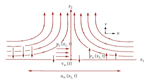
Consider the unsteady viscous fluid over the flat permeable surface. The flow is supposed to be incompressible and is considered in Cartesian coordinate system x1, x2 where x1 is taken along the surface and x2is vertical to the surface as shown in Figure 1.
3. Numerical Procedure for Solution of Model
The Keller–Box method is used to compute the solution to the formulated problem while applying finite difference, Newton iterative, and block elimination techniques. The Keller–Box method is considered one of the most accurate numerical techniques. This methodology has the advantage of not involving any complicated discretization procedure, which makes it superior to many other numerical methods.
3.1. The Finite Difference Approach
3.2. Newton’s Method
3.3. Block-Elimination Method
Once the entries of δ are found, equation (28) can be used to find the (j + 1)th iteration. The described procedure is implemented in Mathematica for the boundary value problems containing non-linear ordinary differential equations along with non-linear boundary conditions considered in the following sections.
4. Convergence and Stability Analysis
As an implicit method for solving problems, the Keller–Box technique consists of reducing the system of differential equations to a system of first-order differential equations. The differential equations are discretized by using central differences, and in the next step, the linearized discretized difference equations are solved by Newton’s method. Finally, they are solved using a tridiagonal block matrix system which gives the solutions to the differential equations. Second-order validity (convergence) and unconditional stability are guaranteed by the method. Cebeci and Bradshaw [28] illustrated the use of the Keller–Box method in their work.
For the unsteady flow of incompressible viscous fluid over a flat permeable moving plate, the stability of dual solution coupled with the model equations (2) and (3) and boundary conditions (4)–(6) is investigated comprehensively. A first time discussion of stability was presented by Merkin [29], and later on, some researchers discussed stability analysis [7]. Based on [29], a positive eigenvalue can be stable compared to a negative one for the dual solution. For a permeable medium, Harris et al. [30] studied the stability analysis of dual solutions for the stagnation point flow.
5. Graphical Results and Discussion
To understand the inspiration of relevant parameters on the velocity components and temperature, equations (11) and (12) under boundary conditions (13) and (14) are numerically solved by the means of the Keller–Box technique [6, 26] for numerous values of the suction (or blowing) parameter Λ. Figures 2–7 are plotted to detect the effects of incipient parameters on temperature profile and components of velocity. Numerical results for heat transfer rate and surface of shear stress present the influence of Λ and Pr parameters.
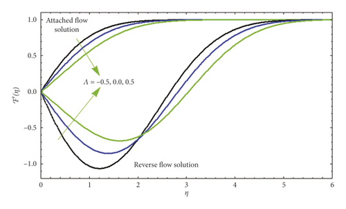
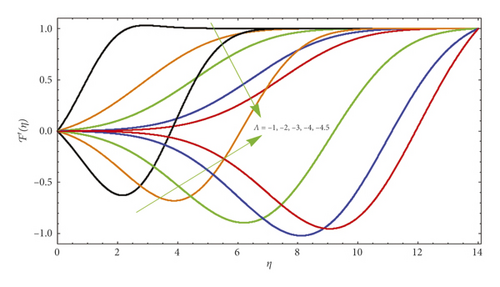
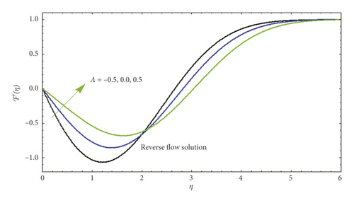
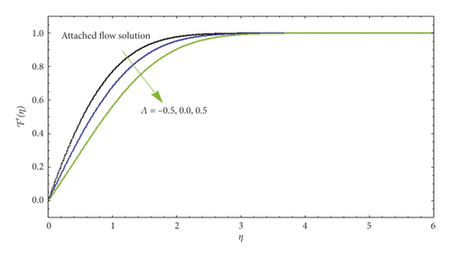
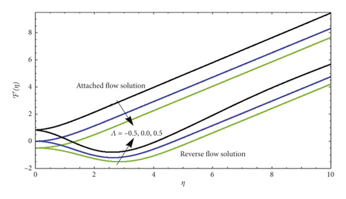
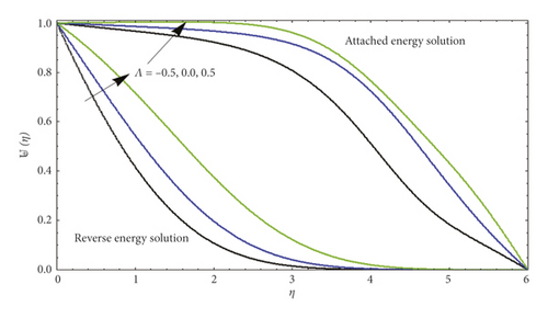
Figure 2 illustrates the dissimilarity of velocity profile corresponding to the plate ℱ′(η) away from the surface of the plate for numerous effects of parameter Ë in both circumstances, namely, AFS and RFS.
In the case of AFS, we can observe that for suction (Λ > 0), the velocity increases with an increase but decreases with an increase for injection (Λ > 0). In addition to affecting the velocity profile close to the plate, the suction reduces the boundary layer, which is responsible for increment in velocity gradient in the vicinity of plate, and as a result of this scenario, the velocity seems to be increased, whereas the opposite behavior is observed at the surface for the case of blowing (Λ > 0). When the flow reversal occurs close to the plate, the velocity of fluid seems to be negative but as the fluid moves from the surface, velocity changes its behavior and at the end converges according to the boundary condition. It is also witnessed that the flow behavior in terms of velocity appears to be same for both the cases of RFS and AFS. Figure 3 explores the behavior of blowing parameter (Λ > 0) on velocity profile for both cases of AFS and RFS. It is clear from the figure that in RFS, the velocity decreases for varying blowing parameters (Λ > 0). As shown in this figure, while the ascending flow is greater than the descending flow (AFS), no flow reversal (RFS) occurs. Based on our experiences of converting ℱ″(0) with Λ earlier, the following effect is stable. The velocity curves in Figure 4 for the case of RFS show its upsurging behavior when the suction parameter is incremented. Physically, the flow is lifted up when the suction is depressed by blowing on the plate.
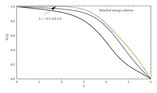
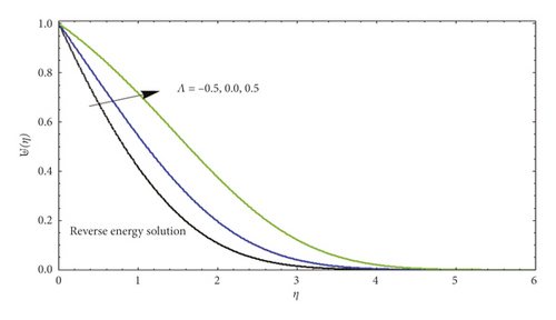
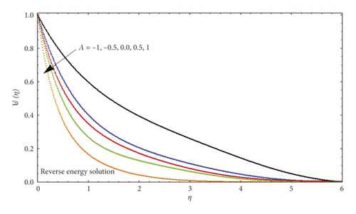
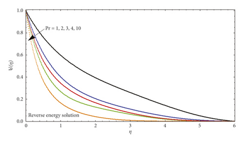
In Figure 5, several values of Λ are compared to show dissimilar vertical components of velocity ℱ′(η). According to our results, ℱ′(η) at a given location increases with blowing but decreases with suction for AFS flows. Figure 6 illustrates the significance of ℱ′(η) varying from AFS to RFS depending on the blowing parameter Λ. After a certain critical value of ℱ′(η) is reached (such that |Λ| critical ≈4.5), only AFS remains. In contrast, |ℱ′(η)| rises with rising suction as the corresponding position is specified in the RFS case. For both AFS and RFS, Figure 7 shows the temperature profile ⊎(η) when Pr = 1 with varying values of Λ. With AFS, it is observed that higher suction parameter (Λ > 0) leads to an increase in temperature of fluid at the point, while at lower injection parameter (Λ > 0), it attracts a higher temperature. Figure 8 is plotted for temperature profile ⊎(η) against numerous significant values of Λ when Pr = 1. This figure shows the increase in attached solution of ⊎(η). Figure 9 shows the temperature profile of reverse solution, with ⊎(η) for numerous significances of Λ and Pr = 1. An increase in temperature is witnessed. Figure 10 shows the temperature profile of attached solution, with ⊎(η) for numerous significances of Λ and Pr = 1. The effect of the Prandtl number Pr on the temperature profiles ⊎(η) is shown in Figure 11. These curves for temperature with increasing Pr are plotted with Λ = 0. An increase in Prandtl number physically means a decrease in thermal conductivity of fluid which causes the reduction of thermal boundary layer thickness. Table 1 shows the comparison of numerical values for attached and reverse flow for different values of suction/injection parameter without magnetic field effects. Numerical values show the validity of adopted method.
| Pr | −⊎′(0) | |||
|---|---|---|---|---|
| Λ | AFS | RFS | ||
| 1.0 | 1.6602 | −2.6360 | 0.5 | 0.41372 |
| 0.7 | 1.4356 | −2.1965 | 0.7 | 0.59341 |
| 0.5 | 1.2754 | −1.6684 | 0.9 | 0.63269 |
| 0.0 | 0.9232 | −0.9851 | 1.0 | 0.68305 |
| −0.5 | 0.6246 | −0.5467 | 1.3 | 0.74329 |
| −0.75 | 0.4800 | −0.3652 | 1.5 | 0.81435 |
| −1.0 | 0.3610 | −0.2524 | 1.7 | 0.97502 |
Table 1 shows the numerical values of skin friction coefficient and heat transfer rate for different vales of parameter Λ. The table demonstrates that the skin friction decreases for decreasing values of Λ for both the cases of AFS and RFS. Moreover, increment in values of the heat flux at wall has been noticed for different values of Prandtl number. Table 2 shows the comparison of different values of skin friction coefficient with the values already obtained. A good agreement has been observed from the obtained values.
| Λ | [23] | [27] | Present | |||
|---|---|---|---|---|---|---|
| AFS | RFS | AFS | RFS | AFS | RFS | |
| 1.00 | 1.6602 | −2.6360 | 1.66022 | −2.63603 | 1.66025 | −2.63603 |
| 0.75 | 1.4643 | −2.1132 | 1.46431 | −2.11321 | 1.46433 | −2.11322 |
| 0.50 | 1.2755 | −1.6684 | 1.27547 | −1.66844 | 1.27548 | −1.66845 |
| 0.00 | 0.9232 | −0.9851 | 0.92321 | −0.98514 | 0.92321 | −0.98514 |
| −0.50 | 0.6137 | −0.5306 | 0.61368 | −0.53058 | 0.61369 | −0.53059 |
| −0.75 | 0.4787 | −0.3724 | 0.47871 | −0.37243 | 0.47869 | −0.37243 |
| −1.0 | 0.3592 | −0.2517 | 0.35918 | −0.25167 | 0.35920 | −0.25166 |
6. Conclusion
- (i)
Heat transfer decreases for increasing Prandtl number Pr.
- (ii)
For AFS, i.e., for suction (Λ > 0), the velocity increases, but it shows opposite trend for injection.
- (iii)
Velocity of fluid upsurges for the case of RFS when the suction parameter is incremented.
- (iv)
A noteworthy result of the analysis includes that (Λ > 0)for blowing parameter (Λ<0), only the AFS exists and gives the unique solution.
Nomenclature
-
- x1:
-
- Surface of plate
-
- x2:
-
- Vertical to the surface
-
- u, ∨:
-
- Velocity components
-
- T:
-
- Temperature
-
- t:
-
- Time
-
- v:
-
- Kinematic viscosity
-
- ue(x1, t):
-
- External inviscid flow velocity
-
- ∨0(x1, t):
-
- Suction or blowing velocity
-
- p:
-
- Pressure
-
- ρ:
-
- Fluid density
-
- Pr:
-
- Prandtl number
-
- Λ:
-
- Suction or blowing parameter
-
- Nux:
-
- Nusselt number
-
- Cf:
-
- Skin friction
-
- τw:
-
- Wall shear stress
-
- qw:
-
- Surface heat flux
-
- Rex:
-
- Local Reynolds number.
Conflicts of Interest
The authors declare that they have no conflicts of interest.
Open Research
Data Availability
All the data are available in the manuscript.


