An Improved VSLAM for Mobile Robot Localization in Corridor Environment
Abstract
Localization is a fundamental capability for an autonomous mobile robot, especially in the navigation process. The commonly used laser-based simultaneous localization and mapping (SLAM) method can build a grid map of the indoor environment and realize localization task. However, when a robot comes to a long corridor where there exists many geometrically symmetrical and similar structures, it often fails to position itself. Besides, the environment is not represented to a semantic level that the robot cannot interact well with users. To solve these crucial issues, in this paper, we propose an improved visual SLAM approach to realize a robust and precise global localization. The system is divided into two main steps. The first step is to construct a topological semantic map using visual SLAM, text detection and recognition, and laser sensor data. The second step is the localization which repeats part work of the first step but makes the best use of the prebuilt semantic map. Experiments show that our approach and solutions perform well and localize successfully almost everywhere in the corridor environment while traditional methods fail.
1. Introduction
Nowadays, many commercial service robots are used for transporting goods in restaurants, hotels, and hospitals, especially during the COVID-19 epidemic time. Among them, the localization research for autonomous mobile robot navigation in a man-made structural environment is an ongoing challenge. In indoor scenes, the most used method is using a 2D laser rangefinder and laser-based SLAM to construct a 2D occupancy grid map [1, 2]. Then the mobile robot performs localization task by AMCL algorithm, which is a particle filter solution [3]. However, when the robot is in a long corridor, the mapping result is always shorter than the real scene and the localization is inaccurate. More seriously, it is easy for the localization process to fall into a symmetrical or similarly wrong position [4]. The reason is that, for the laser sensor used in the symmetrical and similar long corridor environment, the data collected at different times are similar. Therefore, the mobile robot can not get accurate pose information when it performs global localization tasks; besides, it is easy for the robot to converge to the wrong unimodal distribution. More than that, the number of particles increases with the size of the map; then the computing and memory costs also increase. Of all the shortcomings, the main one is the limited amount of data information collected by a 2D laser sensor.
In comparison to a 2D laser sensor, cameras provide more dense information such as point features, textures, lines, objects, and texts. It is one of the most potential sensors that can be used to perceive the environment and localize the pose for mobile robotics.
To address these problems, we propose a novel visual SLAM-based method for mobile robot localization, which is assisted by text information and laser data features extracted from the indoor scene, especially the long, symmetrical, and similar corridor environment. Firstly, the mobile robot initializes the system at the starting position. Secondly, it moves along the middle line of the corridor and constructs a features-based visual map using the visual SLAM method. Thirdly, the robot stops when passing through door areas, rotates the camera toward the doorplate, and records the text content together with the current keyframe node. Lastly, the mobile robot navigates and localizes itself according to the previously built map. The whole framework of the mapping and localization system is depicted in Figure 1.
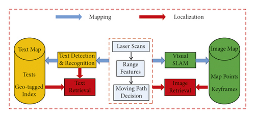
This paper is organized as follows. The related work of visual SLAM, text detection, and recognition are discussed in Section 2. A proposed method using visual SLAM for localization is presented in Section 3. The experiments and discussion are described in Section 4 and Section 5 concludes the paper.
2. Related Work
2.1. Visual SLAM
In the field of visual SLAM, feature-based indirect approaches and photometric-based direct methods are currently two mainstream techniques. The former one extracts salient image features, like points, lines, and planar features, to realize the target. By minimizing the reprojection errors of the matched feature pairs, the camera motion and the depth of map points can be computed. PTAM [5] firstly used the parallel threads to solve the visual SLAM problem; it estimated pose in the tracking thread and refined camera motion in the local mapping thread. ORB-SLAM series [6–8] adopted the idea of parallel threads, added a loop closure thread, and used ORB features in the overall process. It is a state-of-the-art solution in the research field and can be used directly in applications.
The direct methods solve pose estimation by minimizing the pix-level intensity errors from two adjacent images. LSD-SLAM [9] built a semidense map compared to the sparse points map by feature-based SLAM. However, it still needed features extraction for loop closure purposes. SVO [10] used a depth filter model to estimate the depth and filtered outliers. It tracked sparse pixels using the FAST corners and modeled the triangulated depth observations with a Gaussian Uniform distribution. DSO was direct sparse odometry and a probabilistic model without computing keypoints or descriptors [11].
2.2. Text Detection and Recognition
Text signs in the indoor environment have semantic content, which makes easy to realize human-computer interaction. To achieve and understand the scene text information, the OCR techniques usually have two phases, text detection and text recognition, respectively [12].
Text detection is to distinguish text regions from the background of a captured image. Traditional methods based on manually designed features perform well when there exists an obvious construct between the text region and the background part. The stroke width transform (SWT) employed a local image operator to compute the width of approximately textual pixels, searched letter candidates, and grouped letters into text lines [13]. The maximally stable extremal region (MSER) had a real-time detection performance [14]. In addition, it was robust to blur, illumination, and color variation. The morphology-based method extracted high contrast areas as text line candidates [15] and was also invariant to different image changes like lighting, translation, rotation, and complicated backgrounds. CTPN [16] was a connectionist text proposal network and used CNN to detect a text line in a sequence of fine-scale text proposals which were then connected naturally with RNN. The other famous works based on deep learning networks were EAST [17] and IncepText [18].
There are many open-source OCR engines and software using traditional text recognition algorithms can be used, such as Tesseract, Google Docs OCR, and Transym [19]. These methods have relatively high accuracy when the text region has large contrast with the backgrounds and simple text lines. In addition, it does not need a GPU configuration. If the scene texts are multiple fonts, colorful, and complicated backgrounds, then the deep learning approaches based on GPU will be essential. There are two mainstream solutions based on CNN and RNN. The first one uses CNN to extract image features and combines RNN with connectionist temporal classification (CTC) to predict sequence, like CRNN [20]. Another one employs CNN, the Seq2Seq model, and Attention framework [21], which includes encoder and decoder, which adopts ideas from machine translation techniques.
3. Method
When the mobile robot comes into a new environment for the first time, it needs to construct a map and then navigate in the environment according to the built map. We use a monocular camera to perform visual SLAM for both mapping and localization purposes. Different from the traditional laser-based SLAM method, our method uses laser sensor data only for basic geometry features extraction, such as door area, middle of the corridor, or end of the corridor. In addition, text information extracted from the doorplates region is used for semantic localization. The detailed descriptions are as follows.
3.1. Moving Strategy
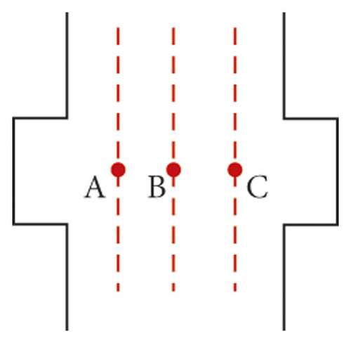
In the map building phase, the mobile robot mainly runs in the SLAM mode utilizing the ORB-SLAM framework. It will create a sparse feature map of the environment from scratch or incrementally update an existing map. However, most of the visual SLAM solutions are used for handheld mode or driverless scenes. In these cases, the moving trajectory of the camera will always be artificially moved on a fixed route and will certainly not lose the tracking of the route according to a prebuilt map. When it comes to the applications of autonomous mobile robots, for instance, the delivery robot moves in a corridor and needs to avoid obstacles when encountering pedestrians; changing the moving route will lose visual feature tracking. Consequently, the mobile robot needs to move within a fixed route range, preferably the middle line of the corridor, as shown in Figure 2, where a robot passes through a doorway area. Three routes indicated by red dotted lines are shown in Figure 2(a), and three positions are indicated by red points. There are only a few matched pairs between the visual features extracted from the image captured in position A and those in position C. Besides, the cameras oriented to different directions also have different matching results, even if in the same position. Therefore, if the mobile robot moves along the left red dotted line as the route and maps the corridor using visual SLAM, it will fail to localize itself when moving along the right red dotted line in the subsequent process. Ideally, the mobile robot moves along the middle red dotted line in Figure 2(a).

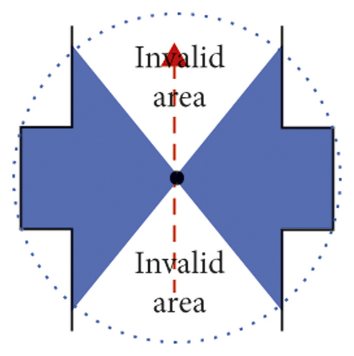
The next problem that needs to be solved is to determine whether the robot is in the corridor area. In most indoor scenes, the laser sensor can get whole valid distance data around the robot; if not, the robot is most likely in the corridor area, as shown in Figure 2(c) where the laser sensor gets two invalid range data regions. The blue areas belong to the range that can be covered by the scanning radius of the laser sensor.
It is easy to find that the mobile robot is at the end of the corridor if only one invalid area satisfies (6). Similarly, if two invalid areas satisfy (6) and are distributed like Figure 2(c), then the robot is most likely located in the middle of the corridor.
According to the above information extracted from the laser scanning data, the mobile robot can autonomously move to the free area along a preset fixed route. In addition, the robot can get a coarse position estimation relative to the corridor.
3.2. Build an Image Map
The next work is using visual SLAM to construct a visual features map along the fixed route which is got based on the previous laser data.
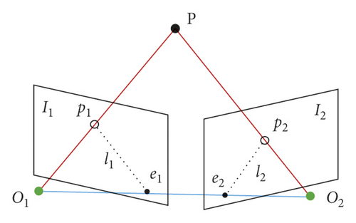
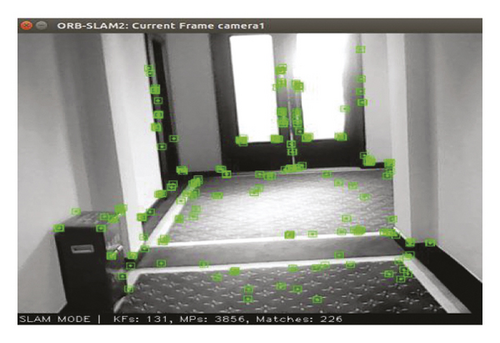
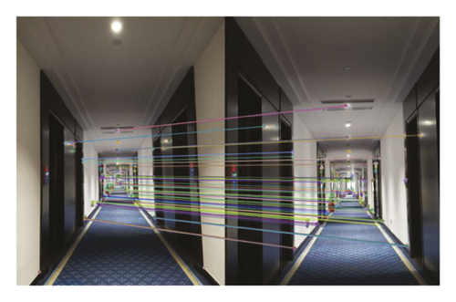
Then the depth of map points in the world coordinate can be computed by using the triangulation method. The constructed map of a corridor is shown in Figure 5, which has sparse points. The blue trapezoidal blocks are camera poses that represent the keyframes of those captured images and will be saved as one part of an image map. The green one means the current frame.

3.3. Extend to a Semantic Map
When the mobile robot performs a cargo transportation task and needs to interact with the user, it is more convenient to use the semantic map closed to human language expression and understanding. To realize this function, text detection and recognition techniques must be used to achieve the text-level information.
The text characters in the indoor environment are usually on the doorplate, room nameplate, signs, or billboard on the wall. The most common is the room number, which can uniquely determine the location of a room. Consequently, the mobile robot just needs to detect and recognize the text information in the door area and extract the room number; then the position of the robot can be determined.
However, the camera mounted on the robot platform captures images in real time and continuously. Most of the images do not have useful text information; processing these images will be a waste of time and computing power. Besides, the text information of a room number would probably only be partially captured in one image; this will lead to misjudgment of the whole semantic result. To solve this problem, we use the laser scanning data to get a preliminary judgment where the doorway area is in the corridor. Then the robot moves to a position facing the door and stops to capture an image with the best perspective. Lastly, detect the text region and recognize the correct room number.
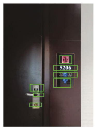
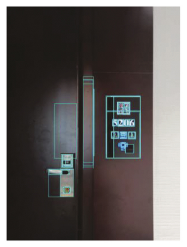
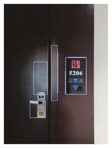
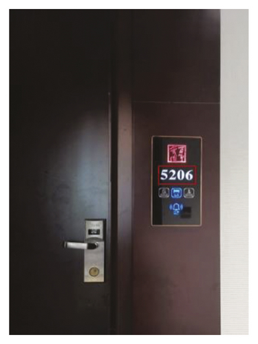
We use two traditional approaches and one deep learning method to detect text regions in a corridor environment, respectively. Figure 6 shows the three detected results; it is obvious that the deep learning method has the best and most accurate detected box. Figure 6(a) is the detected result by using the morphological method which has wrong boxes including the door handle and other text-like signs. Figure 6(b) uses the MSER approach and includes texture area affected by illumination. Figure 6(c) is a processed result from Figure 6(b) by using the nonmaximum suppression (NMS) algorithm [23]. The red rectangle in Figure 6(d) is the ideal result which is got by using the deep learning approach.
The subsequent recognizing phase is relatively easy if a correct text box is detected. In addition, the text information we need is only Arabic numerals. Many open-source OCR solutions can realize this function and have high accuracy [24]. However, to get a high overall text detection and recognition accuracy, we choose to utilize an online deep learning scheme which is called EasyDL from Baidu company [25], https://ai.baidu.com/tech/ocr/general. Thus, we do not need to use GPU as the deep learning processing module, which has high power consumption and cost. Instead, only a WIFI module is needed to access the Internet.
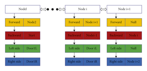
After achieving the text information, an extended semantic map can be accomplished and is shown in Figure 7. The node represents a geo-tagged place which has doors or an intersection, and the edge means a passable route. The images in the node are decided according to the keyframe selection strategy of ORB-SLAM. Three keyframes in each doorway or intersection area are chosen to generate a node. If a corridor is in the form of a straight line or circular, then the semantic map can be represented by the data structure of a two-way linked list. Other cases can be expressed as multilayer quadtree.
3.4. Path Following
When a semantic map is constructed and the robot’s initial pose is known, the navigation task is a path following problem. The path planning algorithm varies with the form of a map. The commonly used data structures are a two-way linked list, multifork tree, and graphs. Consequently, it is a look-up problem and finding the shortest path.
Compared with nodes in a social network or an electronic map of a city, the geo-tagged nodes in an indoor environment used by a personal robot are usually very few. Therefore, search algorithms commonly used in data structures are sufficient.
3.5. Localization Mode
In the localization or navigation mode using the visual SLAM method, the system firstly loads the previously built sparse feature map, then extracts features of a newly captured image, and matches with those from the image map. The difficult thing is not the image matching, but how to capture images in a fixed route and direction that the robot ever traveled before. The method is using laser data to get a coarse place judgment according to (1)–(8).
4. Experiments and Discussion
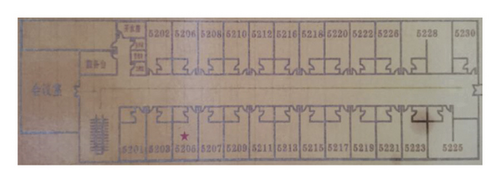
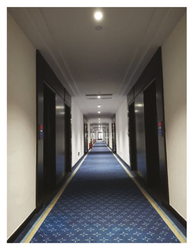
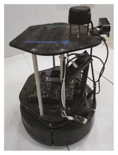
Our experimental platform is a two-wheel differential driving mobile robot equipped with a RPLIDAR A2 and a single perspective camera. The laser sensor has a 360-degree scanning rotation range and 8–12 meters’ distance. The CPU is ARM Cortex-A72 and the RAM memory size is 8 GB. The experimental environment is a long, symmetrical, and similar corridor inside a multiple-story hotel. The length of the corridor is 45 meters and the width is 1.85 meters. Figure 8 shows the corridor and platform. The laser sensor is used for collision detection and basic structural features extraction.
4.1. Lateral Deviation of Fixed Route
The mobile robot moves follow a fixed route which is the middle line along the corridor. According to the laser data computing and features extraction, the mobile robot adjusts its moving direction; a trajectory is shown in Figure 9.
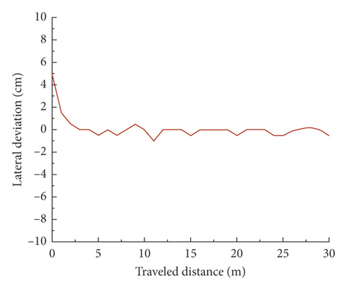
From Figure 9, we find that the precision of laser data is very high, which is suitable for applications with accurate distance requirements.
4.2. Text Detection and Recognition
We collected 150 images from 30 doorway areas in a fifth-floor corridor inside the hotel. Five images in each area are collected from different perspectives and positions, but all of them are roughly facing the door. Because GPU device is not used in the microcomputer system, the offline deep learning model is not adopted for comparative experiments. Firstly, different text detection methods are tested and the average detected text boxes per image are counted. Table 1 shows the result which demonstrates that traditional methods detect many wrong areas as the text regions while online deep learning method performs better. Many lines or outlines in the image are misidentified as text information like numerals or characters. Consequently, WIFI based cloud platform solution is the best solution.
| Method | Average detected boxes per image |
|---|---|
| Morphological method | 7.4 |
| MESR | 9.2 |
| MSER + NMS | 6.9 |
| Ours | 1.1 |
The second experiment is a comparison of the text recognition methods. The accuracy or successful recognition rate is calculated by counting the number of correct character recognitions out of the total tests (150 recognition experiments from 30 doorway areas). We used traditional method solution Tesseract and the online deep learning method to recognize the previously detected text boxes, respectively. Table 2 shows the recognition results. Compared with the traditional method, our online deep learning method achieved high accuracy.
| Method | Total number of recognitions | Number of correct recognitions | Accuracy (%) |
|---|---|---|---|
| Tesseract | 150 | 83 | 55.3 |
| Ours | 150 | 148 | 98.7 |
4.3. Global Localization
In order to achieve a quantitative evaluation of the global localization performance, we placed the robot in 20 different positions in the corridor and used four different methods to perform global localization task, respectively. Due to the different moving strategies in different methods, we set the task ending condition for each positioning process. The AMCL method corresponded to condition when the particles were converged to a single cluster. The ORB-SLAM and text identification methods allowed the robot to rotate one circle in place. In our proposed method, the robot was allowed to adjust its position near the middle line of the corridor, and it needed to move 0.24 meters and rotate 90 degrees on average which were the acceptable range and the requirement of our mobile strategy. The results are shown in Table 3. It is obvious that our approach achieves a higher localization success rate when compared with other methods.
| Method | Test positions | Success times | Correct rate (%) |
|---|---|---|---|
| AMCL | 20 | 9 | 45.0 |
| ORB-SLAM | 20 | 14 | 70.0 |
| Text | 20 | 4 | 20.0 |
| Ours | 20 | 19 | 95.0 |
5. Conclusions
This paper presented a novel mapping and localization approach for an autonomous mobile robot navigating in a long corridor environment. Laser data was used to keep a fixed moving route and extract features for coarse place judgment. Visual SLAM was used to get visual localization and text information for a semantic level purpose.
Although the proposed approach can solve most of the corridor environment localization and semantic interaction with users, the situation in which the mobile robot is inside a specific room was not considered. Therefore, in our future research work, we will pay attention to the topological metric map which can cover all indoor environments. In addition, the 5G communication and cloud computing technology can be used to achieve multiple semantic information in the field of robotics; thus, the mobile robot does not need to configure GPU and other large computing platforms.
Conflicts of Interest
The authors declare that there are no conflicts of interest.
Acknowledgments
This work was supported by the Natural Science Research Project of Guizhou Province Education Department (Grant no. KY[2017]023, Guizhou Mountain Intelligent Agricultural Engineering Research Center) and Doctoral Fund Research Project of Zunyi Normal University (Grant no. ZS BS[2016]01, Aerial Photography Test and Application of Karst Mountain Topography).
Open Research
Data Availability
The labeled dataset used to support the findings of this study is available from the corresponding author upon request.


