Study on Instability Mechanism and Support Scheme of the Tunnel Face in Carbonaceous Phyllite Stratum under High Geo-Stress
Abstract
The tunnel face collapses easily during tunnel construction in weak surrounding rock under high geo-stress. Identifying the instability mechanism of the face and proposing targeted control measures are of great importance to prevent the collapse of the face. Using the setting of the carbonaceous phyllite stratum of the Baima tunnel, a FLAC3D-PFC3D coupled model is used to analyze the influential factors on the stability of the face and optimize the original support scheme. The results show that the instability of the face is rooted in the collapse of the rock above the face, and the bench method with short cycle footage is more conducive to the stability of the face. Compared with single support mode of advanced small pipes, the combined support scheme of long bolts and small pipes can better control the displacement of the surrounding rock and prevent the collapse of the tunnel face. The numerical simulation and field surrounding rock monitoring results verify the rationality of the excavation method, the cycle footage, and the support system. This finding will be of great significance to guide design and construction in weak surrounding rock.
1. Introduction
Highway tunnels have become an indispensable part of the Chinese transportation system. In order to accommodate the huge traffic volume, an increasing number of deep-buried, large cross section and long-distance highway tunnels in complex geological conditions are being constructed. However, tunnel construction in weak surrounding rock under high geo-stress often faces the risk of large deformation of the soft rock and collapse of the tunnel face, which seriously affects construction safety and hinders construction progress [1–3].
Therefore, it is of great importance to study the large deformation of the soft rock under high geo-stress. Some researchers have focused on the deformation characteristics of the weak surrounding rock. Chen et al. [4] studied the deformation mechanism of deep-buried carbonaceous phyllite during tunnel excavation by combining field monitoring with numerical simulation and then proposed a classification criterion for large deformation of the tunnel surrounding rock under high geo-stress. Bai et al. [5] predicted the risk level for the large deformation of a weak surrounding rock tunnel. Chen et al. [6] investigated the reason for the large deformation in 93 layered weak surrounding rock tunnels under high geo-stress and summarized the asymmetric deformation and failure characteristics of layered carbonaceous phyllite under high geo-stress. In view of the extremely complex mechanical response of tunnel construction in weak surrounding rock under high geo-stress, Zhao et al. [7, 8] studied the deformation of a weak surrounding rock tunnel with a combination of laboratory tests and numerical simulation. They observed that the deformation of the weak surrounding rock tunnel had the characteristics of stage and lagging under high geo-stress. Based on the Dujiashan tunnel, Quan et al. [9] studied the deformation and failure characteristics of the weak surrounding rock in a strong seismic zone under high geo-stress. Chu et al. [10, 11] proposed coupled analytical solutions for predicting the mechanical behavior of deep-buried circular lined tunnels in a soft rock mass, which took both the rock rheology and tunnel face advancement effects into consideration. Based on the mixed continuum/discrete numerical model, Meng et al. [12] accurately predicted the deformation results of the large chamber at the Baihetan hydropower plant. Wen [13] used model test to study the deformation and failure process of a weak surrounding rock tunnel and found that the model test results were similar to the FLAC/PFC coupled numerical simulation results.
Many researchers have explored ways to control the surrounding rock deformation. Kong et al. [14] used self-developed numerical calculation software to simulate tunnel excavation; combining it with field monitoring data, they found that adopting the bench excavation method for a horseshoe-shaped cross section tunnel is effective at preventing the occurrence of large deformation of soft rock, while increasing inverted arch thickness during tunnel excavation can also effectively control the deformation of the tunnel vault and inverted arch. Fang et al. [15] used the finite difference software FLAC3D to simulate tunnel excavation and support under different excavation methods, studied the deformation characteristics of the surrounding rock under various working conditions, and discussed the control effect of surrounding rock deformation under different bolt support schemes. Utilizing the convergence constraint method, Guo et al. [16] studied the deformation characteristics of phyllite by combining rock tests with field tests. They found that measures such as optimizing the cross-sectional profile, strengthening support rigidity, and simplifying the excavation steps can effectively control the surrounding rock deformation in steeply inclined layered phyllite stratum under high geo-stress.
To sum up, scholars have carried out a large number of studies on the characteristics of large deformation and its control measures in weak surrounding rock tunnels. From the basic principle of the ADECO-RS approach, we can see that the key to controlling the stability and deformation magnitude of a weak surrounding rock tunnel is to control the deformation of the tunnel face [17–20]. For example, Pan and Dias [21] found that the use of bolts as a reinforcement technique was beneficial to improve the stability of tunnel face during tunnel excavation and explored the supporting effects on the tunnel face with different bolt lengths through numerical simulation. An et al. [22] used the Winkler foundation model and rigid limit equilibrium to study the stability of tunnel face under the support of advanced pipes. They found that the tunnel face stability can be improved through increasing the pipe diameter and the displacement at the face increased with the increase of the pipe ring spacing and the pipe longitudinal spacing. However, there is little research on the relationship between the instability mechanism of the tunnel face and the support in a weak surrounding rock stratum under high geo-stress. Li et al. [23] studied the macroscopic mechanical behavior of granite based on a mesostructure-based model and achieved remarkable research results. In the same way, this study studies the instability mechanism of the tunnel face from the microscopic particle structure of rock mass.
Using the carbonaceous phyllite stratum of the Baima tunnel project as the study setting, this study firstly uses a FLAC3D-PFC3D coupled model to analyze the instability mechanism of the tunnel face by simulating tunnel excavation and to investigate the influence factors on the stability of the tunnel face. Based on the results, the original support scheme of the tunnel face is optimized depending on the instability mechanism of the tunnel face. The stability of the surrounding rock at the tunnel face after tunnel excavation under different optimized support schemes is compared by combining the PFC3D-FLAC3D coupled calculation model with field measurement. Eventually, a reasonable and feasible support scheme for the tunnel face in carbonaceous phyllite stratum under high geo-stress is proposed.
2. Engineering Background
The Baima tunnel is located on the Jiumian highway in Mianyang City, Sichuan Province, China. The starting and ending mileage of the tunnel right line is YK34 + 664∼YK47 + 664, and the starting and ending mileage of the left line is K34 + 707∼K47 + 20. The tunnel adopts 4 lanes of two-way separation with a net width of 10.25 m and a net height of 5 m, and the maximum buried depth is about 1100 m. The stratum lithology of the tunnel crossing is mainly carbonaceous phyllite and slate, and the surrounding rock grade is mainly V grade. The geological section of the tunnel is shown in Figure 1.
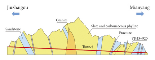
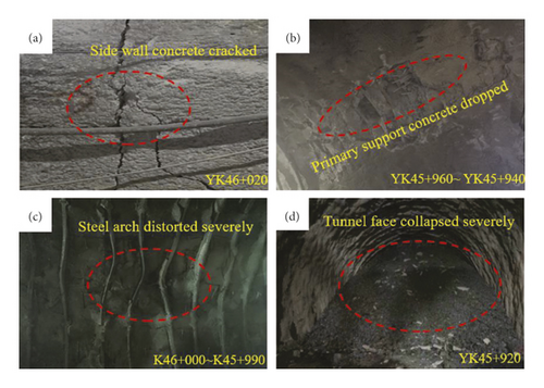
Field disclosures showed that most of the surrounding rock is fragmented, with developed joint fissures, low integrity, and poor self-stability when the tunnel passed through the carbonaceous phyllite in the YK45 + 920 section. Test using the stress relief technique indicated that the maximum principal stress was perpendicular to the tunnel direction with a value up to 14.92 MPa, as listed in Table 1. During tunnelling in the carbonaceous phyllite stratum, there was serious large deformation of the soft rock under high geo-stress, the primary support concrete cracked, the steel arch frame was seriously distorted and even broke off, the surrounding rock around the tunnel face lost its stability, and different degrees of collapse occurred, as shown in Figure 2.
| Measure location | Principal stress | Valve (MPa) | Azimuth angle (°) | Dip angle (°) |
|---|---|---|---|---|
| YK46 + 794 | Maximum principal stress | 14.92 | 100.7 | 8.7 |
| Intermediate principal stress | 5.21 | 45.2 | 79.6 | |
| Minimum principal stress | 4.60 | 191.6 | 5.7 |
3. Acquisition of Material Parameters
3.1. Selection of Computing Software and Computing Model
Since the discrete element model can simulate the motion law of the granular body very well under nonlinear interaction, it is widely used in studies of the stability of broken surrounding rock tunnel [24–28]. According to field investigation, the tunnel surrounding rock is mainly carbonaceous phyllite with the characteristics of broken structure, poor mechanical properties, and a morphology that is close to granular body. The displacement of the rock mass at the tunnel face gradually increases until it fails and separates from the matrix after tunnel excavation. It is difficult to use traditional continuum-based software to simulate this instability failure phenomenon.
Cundall and Strack [29, 30] developed a DEM program named Particle Flow Code (PFC). Their subsequent studies proved that PFC had obvious advantages in analyzing the micro-structure evolution of granular materials. In this study, PFC3D is utilized to simulate tunnel excavation to study the movement development law of surrounding rock particles after tunnel excavation and analyze the instability characteristics of the tunnel face. In light of the loose characteristics of the surrounding rock, the linear contact model is adopted, as shown in Figure 3.
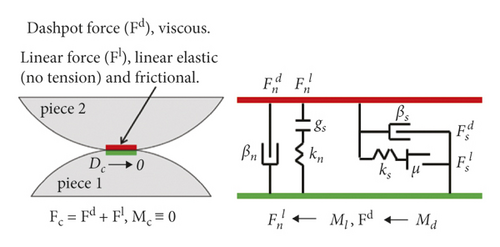
The linear model [31, 32] describes the behavior of an infinitesimal interface that does not resist relative rotation so that the contact moment equals zero (MC ≡ 0). The contact force is resolved into linear and dashpot components (FC = Fd + Fl). The linear component provides linear elastic (no tension), frictional behavior, while the dashpot component provides viscous behavior. The linear force is produced by linear springs with constant normal stiffness (kn) and shear stiffness (ks). The dashpot force is produced by dashpots with viscosity given in terms of the normal critical-damping ratio (βn) and shear critical-damping ratio (βs). The linear springs act in parallel with the dashpots.
3.2. Similarity Relation and Acquisition of Macro Material Parameters
The calculation process of the discrete element model requires large computing resources. If the tunnel prototype is calculated, millions or even tens of millions of particles are needed, which leads to a long calculation time. Therefore, the scale-model method is used for model calculation, and the geometric similarity ratio CL = 10 is ultimately determined due to the requirements for computational accuracy and computational power.
The macroscopic mechanical parameters of tunnel surrounding rock are obtained from a geological investigation report. The geometric similarity ratio CL = 10 and bulk density similarity ratio Cγ = 1 are selected as the basic similarity ratios to obtain the material parameters of the scale model. The material parameters are listed in Table 2.
| Parameter | ρ (kg/m3) | E (GPa) | μ | c (MPa) | φ (°) |
|---|---|---|---|---|---|
| Prototype | 1980 | 1.3 | 0.4 | 0.02 | 27 |
| Model | 1980 | 0.13 | 0.4 | 0.002 | 27 |
| Similarity ratio | 1 | 10 | 1 | 10 | 1 |
3.3. Acquisition of Micro-Material Parameters
According to the discrete element theory, the microscopic parameters determine the macroscopic response of granular materials. Only by selecting the correct microscopic parameters, the real-world situation can be reflected by the simulation. Generally, if the macroscopic mechanical parameters obtained by mechanical tests are consistent with the actual mechanical parameters of the material, the calibrated parameters are considered to be reasonable [33, 34]. The microscopic particle parameters corresponding to the macroscopic mechanical parameters of the rock materials in Table 1 are calibrated by the PFC3D triaxial numerical test model. Numerical triaxial tests are carried out under confining pressures of 50 kPa, 100 kPa, 150 kPa, 200 kPa, and 300 kPa, respectively, in order to obtain the constitutive relation curves, as shown in Figure 4. Ultimately, we get the target calibration values by continuously adjusting the microscopic parameters.
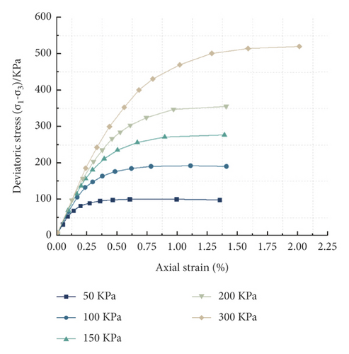
Internal friction angle φ = 26.97° and cohesion c = 7.69 kPa can be calculated from equation (2). There is little difference between the experimental results and the macroscopic mechanical parameters of the actual model listed in Table 1, which indicates that the calibration result is reasonable. Then, the microscopic parameters of the model are obtained, as listed in Table 3, and the corresponding numerical model is finally established.
| Particle density ρ (kg/m3) | Contact modulus of particles Ep (GPa) | Particle friction factor μp | Maximum/minimum particle size ratio Rmax/Rmin | Contact stiffness ratio Kn/Ks |
|---|---|---|---|---|
| 1980 | 0.14 | 0.3 | 16 | 2.0 |
4. Analysis of the Instability Mechanism and Influence Factors on the Tunnel Face
4.1. Establishment of Continuous-Discrete Stratum Model
The influence range after tunnel excavation is about 3–5 times the tunnel diameter [36, 37]. In order to reduce the boundary effect, the net distance from the tunnel excavation contour to the model boundary is 3D (D is the tunnel excavation span, about 12 m). Because this study aims to explore the instability characteristics and effective support measures of the tunnel face and mainly analyzes the deformation development process of the surrounding rock at the tunnel face after excavation, the surrounding rock far away from the tunnel face is not analyzed. In order to save model calculation time, the whole stratum model is divided into the core discrete part and the peripheral continuous part. The core discrete part is established using PFC3D software based on DEM and the peripheral continuous part is established suing the finite element code three-dimensional (FLAC3D) software based on the finite difference method (FDM). The simulation of the tunnel excavation and the stability analysis of the tunnel face are completed in the core discrete area.
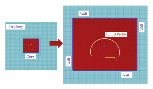
First, FLAC3D is used to establish the whole continuous stratum model according to the macroscopic parameters of the stratum listed in Table 1, and then the core discrete part is hollowed out. With the help of PFC3D, the discrete stratum model is established according to the micro parameters of the stratum listed in Table 2. Then, the built-in FLAC3D loading module in PFC3D is opened and the peripheral continuous stratum part is imported to construct the continuous-discrete coupled stratum model, as shown in Figure 5. The size of the core discrete part model is 2.4 m × 1 m × 2 m, and a total of 550089 particles are generated. Particles with the size of 0.008 m–0.0128 m obey uniform distribution and the porosity of the core discrete part model is 0.4.
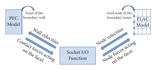
The coupling principle of PFC3D and FLAC3D is to take the wall unit as a coupled bridge to transfer velocity and force to each other. The wall unit converts the influence of the finite element on the discrete element into a displacement boundary condition and converts the influence of the discrete element on the finite element into a stress boundary condition [38, 39]. The original rock stress obtained by the results of the stress relief technique test is used as the stress boundary condition of the coupled model. During model calculation, a displacement wall consistent with the finite element is set at the coupled interface to restrict the displacement of the particle collection, and then the contact force of the particle on the wall is applied to the node of the finite element. The coupling principle is shown in Figure 6.
4.2. Analysis of the Instability Characteristics on the Tunnel Face
The excavation scheme of the bench method with 2 m excavation footage is adopted in the field. Because the geometric similarity ratio CL = 10 is being used, the corresponding excavation footage is 0.2 m in the numerical calculation model.
Figure 7 shows the deformation development process of the surrounding rock after the tunnel upper step is excavated by the bench method with 2 m excavation footage. As time passed, the deformation of the unsupported rock mass near the tunnel face became larger until it became completely unstable, represented by the dark blue zone in Figure 7. As time passed, the rock mass in the dark blue zone broke away from the matrix, and the dark blue zone extended to the depth of the surrounding rock and caused the deep rock mass to fall. For convenient analysis, this zone is called the “collapse risk zone” in this study.
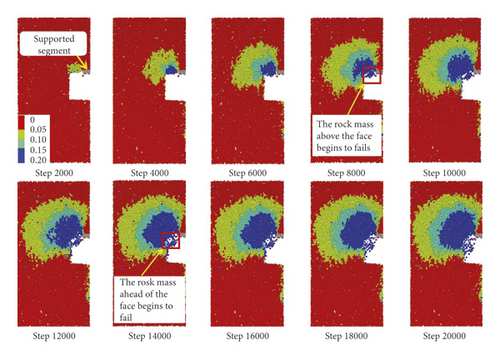
As shown in Figure 7, the unsupported rock mass near the tunnel face formed a large collapse risk zone when the calculation time reached 14,000 steps, and serious collapse occurred at the tunnel face at the same time. We can also see that the unsupported rock mass above the tunnel face experienced instability first when the calculation time reached 8000 steps, and the rock mass ahead of the face began to collapse subsequently when the calculation time reached 14,000 steps. The large-scale collapse of the tunnel face was rooted in the instability of the rock above the face, which led to the correlated slip of the rock ahead of the face. The results of the numerical simulation are very close to the reality.
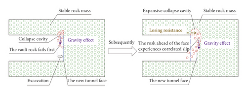
After tunnel excavation, the surrounding rock near the tunnel face became looser than before due to stress relief. Under the effect of gravity, the displacement of the surrounding rock above the tunnel face increased faster than that in front of the face, and the range of the collapse risk zone gradually extended from the top of the face to the front of the face. As time passed, the unsupported rock above the tunnel face experienced instability first. The further expansion of the collapse cavity caused by the continuous collapse of the upper rock mass enlarged the free face of the tunnel face, which led to the correlated slip of the rock mass in front of the face. It can be seen that the surrounding rock above the tunnel face should be reinforced first, and then the surrounding rock ahead of the face should be reinforced. The instability mechanism of the tunnel face is shown in Figure 8.
4.3. Influence of Excavation Footages on the Stability of the Tunnel Face
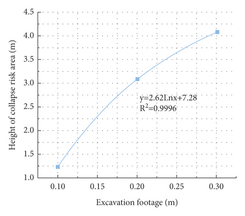
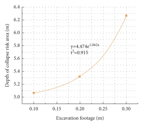
Three footages (i.e., 1 m, 2 m, and 3 m) are selected for working condition comparison. Figure 9 shows the displacement distribution law of the surrounding rock near the tunnel face under different excavation footages. The height of the collapse risk zone above the tunnel face is 3.1 m for the 2 m excavation footage, which is 2.5 times higher than for the 1 m excavation footage. The height of the collapse risk zone above the tunnel face is 4.11 m for the 3 m excavation footage, which is 3.3 times higher than for the 1 m excavation footage. The depths of the collapse risk zones in the axial direction of the tunnel are 5.07 m, 5.33 m, and 6.27 m for 1 m, 2 m, and 3 m, respectively. We can also see that the tunnel face experiences the most serious collapse under 3 m cycle footage, followed by 2 m cycle footage and 1 m cycle footage. The longer the excavation footage is, the more disturbed the surrounding rock near the face is, and the more unstable the face is.

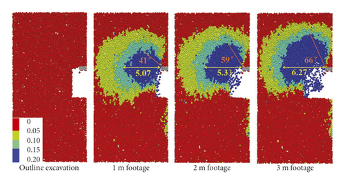
Figure 10 shows the distribution law of the collapse risk zones for different cycle footages. It can be seen from the data fitting that with the increase of the cycle footage, the range of the collapse risk zone gradually increases. Especially along the tunnel axis direction, the depth of the collapse risk zone increases exponentially with the increase of the cycle footage. The influence of the cycle footage on the surrounding rock ahead of the face is greater than on the surrounding rock above the face.
4.4. Influence of Excavation Methods on the Stability of the Tunnel Face
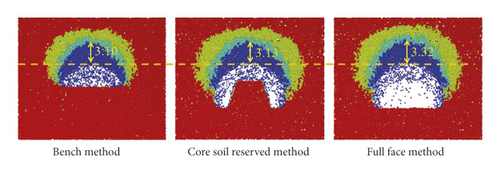
In order to further explore the influence factors on the characteristics of the instability of the tunnel face in weak surrounding rock, the bench method, reserved core soil method, and full section method are used to simulate tunnel excavation under 2 m cycle footage. Figure 11 shows the displacement distribution law of the surrounding rock near the tunnel face for different excavation methods. In the vertical direction of the stratum, there is little difference among these three excavation methods in the height of the collapse risk zone: all are about 3 m. Thus, under the premise of the same excavation span and excavation footage, the depth of the collapse risk zone caused by tunnel excavation has little relationship with the excavation method. In the axial direction of the tunnel, compared with the full section method and the reserved core soil method, the depth of the collapse risk zone generated by the bench method is relatively the minimum, about 80% of the other two excavation methods. The disturbed range of the surrounding rock when using the bench method is the smallest, and the tunnel face experiences the most serious collapse under full section excavation, followed by the reserved core soil method and the bench method. Considering construction safety and construction progress, the excavation scheme of the bench method with 2 m excavation footage is the best choice.
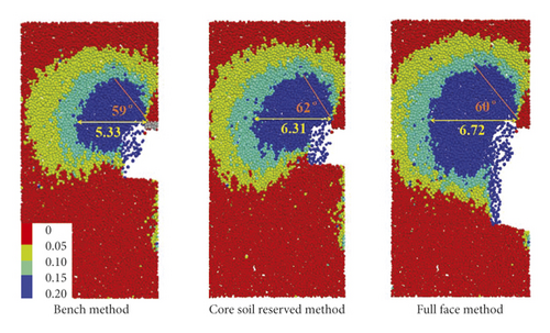
In summary, we constructed a coupled calculation model using PFC3D and FLAC3D to simulate tunnel excavation and recorded the deformation process of the surrounding rock near the tunnel face by time step. Further, we explored the influence factors on the instability characteristics of the tunnel face. The results show that the large-scale collapse of the tunnel face is rooted in the instability of the rock above the face, which further leads to the correlated slip of the rock ahead of the face. Therefore, controlling the displacement of the surrounding rock above the face is the key to prevent large-scale instability of the face. The longer the excavation footage is, the more disturbed the surrounding rock near the face is, and the more unstable the tunnel face is, so adopting short footage to excavate the tunnel is an effective way to control the deformation of the weak surrounding rock. Under the premise of the same excavation span and excavation footage, the height of the collapse risk zone caused by tunnel excavation has little relationship with the excavation method. Compared with the full section method and the reserved core soil method, the depth of the collapse risk zone generated by the bench method is relatively the minimum, so the disturbed range of the surrounding rock when using the bench method is the smallest. Considering construction safety and construction progress, the excavation scheme of the bench method with 2 m cycle footage is finally selected.
5. Optimization of Support Scheme
5.1. Original Support Scheme
Through the study of the instability mechanism of the tunnel face, we determined that the bench method with 2 m cycle footage is the most reasonable method for tunnel construction in carbonaceous phyllite stratum. However, as shown in Figure 7, the surrounding rock collapse risk zone was still large after tunnel excavation using the bench method with 2 m cycle footage, and part of the rock mass near the tunnel face lost its stability due to excessive displacement without any support measures. In order to control the displacement of the surrounding rock, targeted support measures can be taken for the surrounding rock above and ahead of the face depending on the instability mechanism of the tunnel face.
Advanced pipe can improve the stress environment of the surrounding rock ahead of the tunnel face. As an effective support method, it can effectively control the displacement development of the surrounding rock near the tunnel face. Therefore, advanced pipe support is frequently used in tunnel excavation under complex geological conditions [40–42].
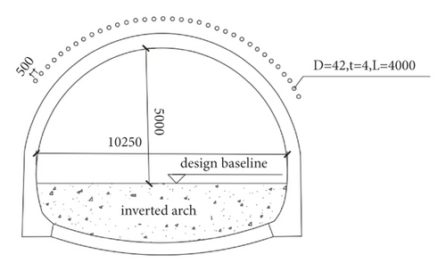
The surrounding rock in front of the tunnel face is prestrengthened by advanced small pipes with external diameter D = 42 mm and thickness t = 4 mm on-site. The length of the small pipes is L = 4 m, the circumferential spacing is δ = 0.4 m, and the application range is 120° along the centre angle of the vault. The support scheme is shown in Figure 12. However, the surrounding rock near the tunnel face still experienced serious instability after tunnel excavation using this support scheme, as shown in Figure 2(d). Therefore, to optimize the support parameters of the advanced small pipes, it is proposed to increase their support length.
5.2. Support Comparison of Long and Short Pipes
According to field investigation, the tunnel face still bears the risk of instability under the support of 4 m advanced small pipes. In order to explore whether increasing the support length of the advanced small pipes can better control the displacement of the surrounding rock, a discrete (stratum)-continuous (support structure) coupled model is constructed using PFC3D and FLAC3D to simulate tunnel excavation with the support of advanced small pipes of 4 m (short) and 8 m (long) lengths. This model is then used to analyze the displacement variation law of the surrounding rock near the tunnel face under each support condition. In the stratum model established in Section 4, the advanced small pipes continuous structure units are established along the tunnel excavation contour in the core discrete stratum area using FLAC3D’s built-in command and the stress boundary condition is applied on the peripheral continuous stratum model. After initial equilibrium, the bench excavation method with 2 m cycle footage is used to simulate tunnel excavation.
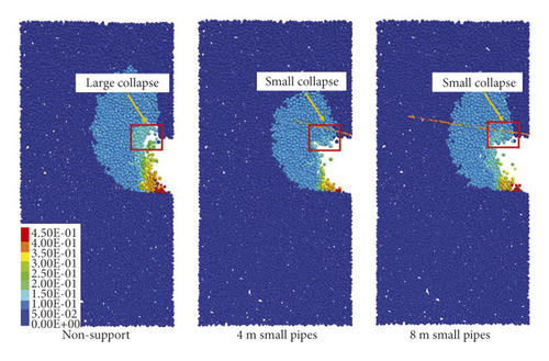
Figure 13(a) shows the displacement nephogram of the surrounding rock under different support conditions (large collapse: collapse occurs both ahead of the face and above the face; small collapse: collapse only occurs ahead of the face). In the no-support condition, the surrounding rock near the tunnel face experienced serious collapse. Compared with the no-support condition, the displacement of the surrounding rock near the tunnel face was effectively controlled using the support of the advanced small pipes, and the collapse range of the tunnel face is significantly reduced. Before tunnel excavation, the small pipes connected the unstable rock ahead of the tunnel face and improved the integrity of the loose broken surrounding rock near the face. The rock layers simply stacked together in front of the tunnel face put together as a whole, which is similar to a composite beam under the support of advanced small pipes. After excavation and stress relief, these rock layers deformed together. At the same time, the shear strength and tensile strength provided by the small pipes improved the shear and bending capacities of the composite beam, stabilized the rock mass that had slip risk, and reduced the collapse risk of the tunnel face.

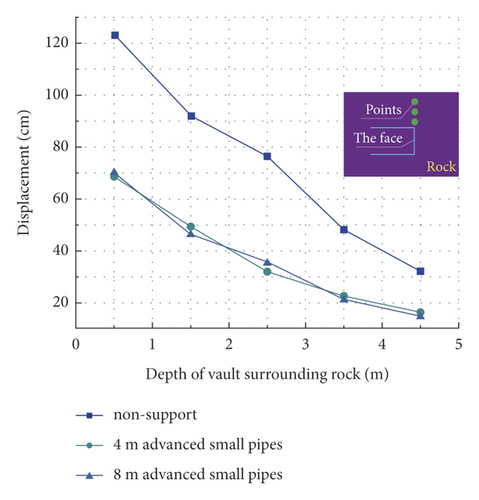
Due to the use of a scale model (CL = 10), the actual displacement of the surrounding rock should be expanded in the same proportion. As shown in Figure 14, under the support of the advanced small pipes, the vault settlement within 2 m ahead of the tunnel face is only 60% of that under the no-support condition. The regularly arranged advanced small pipes can squeeze and bond the surrounding rock within a certain depth ahead of the tunnel face, which is equivalent to forming a stable and continuous body that is similar to a balanced arch shell along the tunnel contour in the stratum ahead of the tunnel face. The stable and continuous arched shell can bear the pressure of the surrounding rock above and ahead of the tunnel face, improve the stress environment, and reduce the deformation of the surrounding rock.
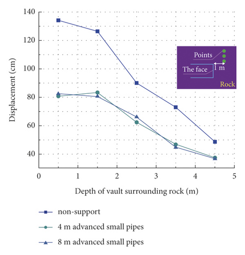
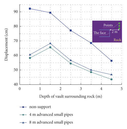
However, there is little difference in the control effect of short and long advanced small pipes on the surrounding rock deformation. As shown in Figure 13(b), the axial deformation of the long pipes in the middle part is the largest, and the closer to the tail, the smaller the deformation is until it is 0, which means that the end of the long pipes is basically free from the extrusion effect of the broken rock mass. The rock mass at the end of the long pipes exceeds the disturbance range caused by tunnel excavation, which can be self-stable, so the long pipes are too long to be fully utilized. Figure 13(a) shows that when the length of the small pipe is 4 m, it basically covers the loose zone of the tunnel face, and can support the loose zone of the surrounding rock ahead of the face.
At the same time, the same size of the elevation angle is used in the simulation calculation, so that the thickness of the arch shell formed under the action of the long or short small pipes is the same, which can effectively resist the rock pressure ahead of the tunnel face. Even if the length of the pipes is increased to 8 m, the displacement of the tunnel face is not significantly reduced, so there is little difference between the support of long and short pipes. Considering construction difficulty and economics, the support scheme of 4 m small pipes can still be used in the field. However, due to the influence of the elevation angle of the advanced small pipes, a small-scale surrounding rock collapse occurs because of the large displacement of the rock mass ahead of the tunnel face. Therefore, the reinforcement in this section should be strengthened during tunnel excavation.
5.3. Design of Combined Support Scheme
As shown in Figures 13 and 14, under the support of the 4 m advanced small pipes, the displacement of the surrounding rock above the tunnel face exceeds 70 cm. At the same time, due to the influence of the elevation angle of the advanced small pipes, the surrounding rock in front of the tunnel face still experiences a large displacement and partially collapses. This does not meet the requirement of safety for construction.
A large number of studies have shown that bolts can improve the mechanical parameters of surrounding rock, effectively strengthen the bearing capacity of surrounding rock, and reduce the deformation of surrounding rock [43–46]. The study on the instability mechanism of the tunnel face in this study shows that the instability of the tunnel face is rooted in the collapse of the rock above the face. After tunnel excavation, bolts are used to radially support the surrounding rock above the tunnel face, improve the mechanical parameters, and strengthen the bearing capacity of the surrounding rock, which can solve the instability of the tunnel face at the source. Using the single support mode of advanced small pipes supports the tunnel face in carbonaceous phyllite stratum with high geo-stress can-not meet engineering requirements. Therefore, we consider a combined support scheme of advanced small pipes and bolts.
The simulation of the advanced small pipes shows that their support effect will not increase with the increase of the length of the pipes, which is due to a certain loose range of the surrounding rock after tunnel excavation. When the thickness of the arch shell formed by the small pipes is basically able to cover the loose range of the surrounding rock, the length of the small pipes is no longer the main cause of the support effect. Considering the economic benefits, construction difficulty, and other factors, it is also necessary to compare the support effect between long and short bolts. Hollow bolts 32 mm in diameter and 6.5 mm in thickness with the length of 4 m (short) and 8 m (long) and spacing of 1.2 m × 1 m between the bolts are simulated. Because the bolts possess tensile and shear resistance in the surrounding rock, we also adopt pile elements to simulate bolts in the numerical calculation. The diameter of the solid bolt ϕ0 = 28 mm can be calculated by the equivalent bending stiffness in equation (3).
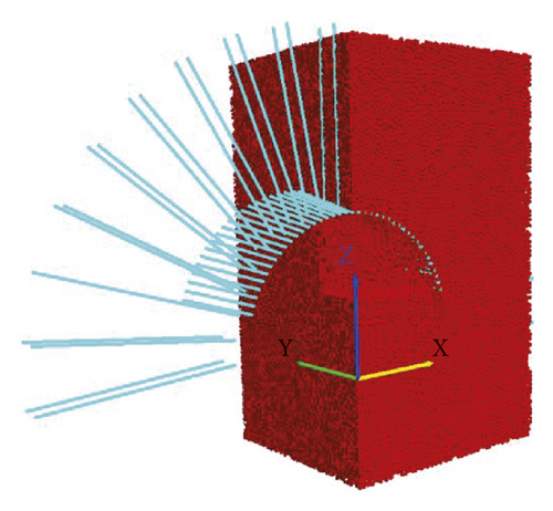
After the stratum model reaches initial equilibrium, tunnel excavation is simulated under the prereinforcement of 4 m advanced small pipes. After each cycle of tunnel excavation, bolts continuous structural units along the tunnel contour are established using the built-in command in FLAC3D. The coupled support model is shown in Figure 15.
After each cycle of tunnel excavation, bolts are used to support the surrounding rock near the tunnel face, as shown in Figures 16(a) and 16(b). Due to the use of a scale model (CL = 10), the actual displacement of the surrounding rock should be expanded in the same proportion. The zone where its displacement exceeds 15 cm is called the “large displacement zone” in this study. The area of the large displacement zone is about 73.9 m2 with the support of short bolts. The large displacement zone is about 35.5 m2 with the support of long bolts, which is 50% of that with the support of short bolts. At the same time, under the effect of the short bolts, the depth of the large displacement zone above the tunnel face is 4.5 m, which is 3 times that under the effect of the long bolts.
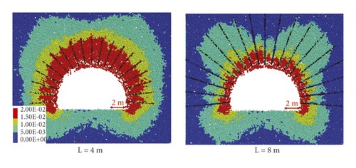
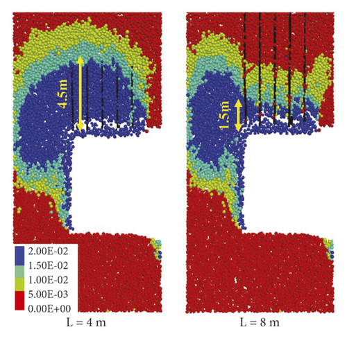

The long bolts have a better control effect on the displacement of the surrounding rock and can significantly prevent the instability of the tunnel face. This is because the short bolts are not anchored into the stable rock mass and are instead located in the loose zone caused by the tunnel excavation. In contrast, the long bolts are anchored into the depth of the stable rock mass, where they can anchor the loose rock mass in the stable matrix and give full play to the suspension effect of the bolts. It can also be seen from Figure 16(c) that the tails of the short bolts have the largest deformation and largest stress, while the tail deformation of the long bolts is small, as low as 0. This can be explained by the fact that the long bolts are anchored in the stable rock mass.
As shown in Figures 14 and 17, compared with the single support mode of advanced small pipes, the displacement of the surrounding rock above the tunnel face is less than 25 cm with the combined support scheme of advanced small pipes and bolts; this is only about 30% of the displacement with the single support mode of advanced small pipes. The displacement of the surrounding rock in front of the tunnel face is also significantly controlled, and there is no collapse at the tunnel face. From the study of the instability mechanism of the tunnel face, it can be seen that due to the application of radial bolts after tunnel excavation, the surrounding rock above the exposed tunnel face is reinforced in time, which strengthens the bearing capacity of the surrounding rock above the face and effectively controls the development of instability in the face at the source.
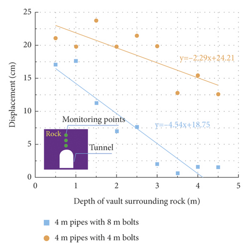
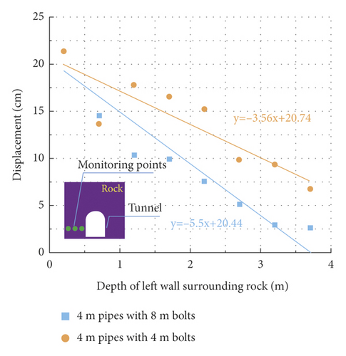
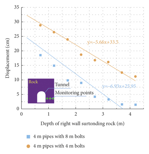
As shown in Figure 17, with the combined support scheme of advanced small pipes and bolts, the displacement of the surrounding rock around the tunnel decreases linearly with the increase of the surrounding rock depth. After tunnel excavation, the fitting line of the surrounding rock displacement under the effect of long bolts is steeper and the descending speed decreases more quickly than that under the effect of short bolts. Under the combined support scheme of advanced small pipes and long bolts, the settlement of the surrounding rock above the tunnel face at 4 m depth is only 5.9 mm, which is basically stable. However, under the combined support scheme of advanced small pipes and short bolts, the settlement of the surrounding rock above the tunnel face at 4 m depth exceeds 150 mm, and there is also a risk of collapse due to the large displacement of the surrounding rock. Meanwhile, at the same surrounding rock depth, the displacement of the surrounding rock with long bolt support after tunnel excavation is smaller than that with short bolt support.
It can be seen that the long bolts are anchored into the stable rock layers, giving them a better control effect on the displacement of the surrounding rock above the tunnel face than short bolts and better mitigating the collapse risk of the tunnel face at the source. Ultimately, the combined support scheme of 4 m advanced small pipes and 8 m long bolts is determined for the tunnel face in carbonaceous phyllite stratum.
5.4. Engineering Practice
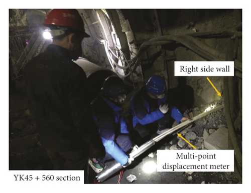
The displacement of the surrounding rock in the YK45 + 560 section is recorded by a multipoint displacement meter, which is shown in Figure 18. The field displacement test results are shown in Figure 19. The variation law of actual rock displacement is basically consistent with the numerical simulation results. The rock displacement decreases linearly with the increase of the surrounding rock depth, and the maximum settlement of the surrounding rock above the tunnel face is only 9.81 cm (as obtained from the fitting curve), which meets the requirement of safety for construction.
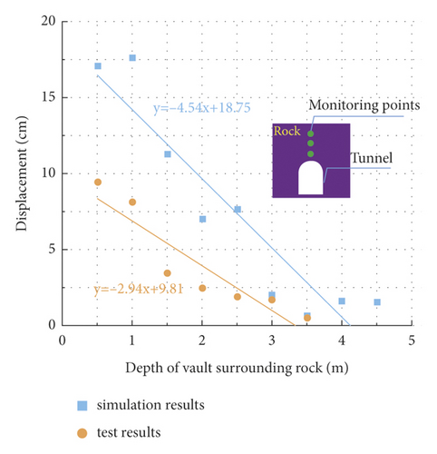
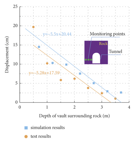
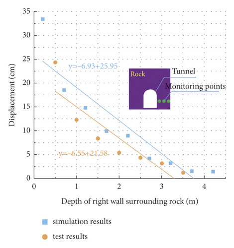
However, the simulation results are always slightly larger than the field measurement because particle flow simulation is adopted in the numerical calculation in this study, and particle flow simulation is unable to carry out the grouting simulation of the advanced small pipes and the bolts. In reality, grouting small pipes and hollow grouting bolts are used. The slurries that infiltrate into the surrounding rock can play a role in improving the stress environment and strengthening the bearing capacity of the surrounding rock. Consequently, the control effect on the displacement of surrounding rock in reality is better than that in the numerical simulation.
6. Discussion
In this study, the excavation stability of the tunnel face and its effective control measures in weak surrounding rock are studied by means of numerical simulation combined with field monitoring. The instability mechanism of the face in carbonaceous phyllite stratum is revealed, and excavation using the bench method with 2 m cycle footage and the combined support scheme of advanced small pipes and bolts are proposed. The numerical simulation and surrounding rock monitoring results from the field verify the rationale for using the excavation method, cycle footage, and support system that can effectively control the surrounding rock deformation at the tunnel face and further prevent the instability of the face. The instability mechanism and support mechanism of the face are further discussed below.
6.1. Instability Mechanism of the Face
In this study, the excavation stability of the tunnel face is studied using DEM, and the numerical simulation reproduces the instability process of the tunnel face in the field. As shown in Figure 7, after tunnel excavation, the displacement of the rock mass above the face gradually increases until it fails and separates from the matrix. Further, the rock mass in front of the face loses its lateral constraints and experiences correlated slip failure. This continuous instability failure process is vividly demonstrated by the PFC3D software based on DEM, which is not available in traditional continuum-based software, such as FLAC and ANSYS.
Many scholars have used traditional continuum-based software based on the finite element method (FEM) or finite difference method (FDM) to study the stability of the tunnel face. The comprehensive FEM study on the face stability of shield tunnels was carried out by Zhang et al. [47, 48], who used stepwise-reduced support pressure to achieve collapse failure at the tunnel face and took the critical support pressure to judge whether the face had been damaged. Höfle et al. [49, 50] studied the stability of the tunnel face through the deformation development law of the surrounding rock at the face and determined whether the face is unstable according to the deformation value of the face. These studies indirectly described the instability of the face through a certain quantitative index but could not reverse the essential phenomenon that the rock mass at the face fails and breaks away from the matrix due to excessive deformation. What is more, they were unable to show the whole continuous instability process of the face.
Therefore, DEM is more advantageous to study the instability of the face in weak surrounding rock. The numerical simulation process can clearly demonstrate the instability process of the face, which is more realistic.
6.2. Coupling Effect of Support Structure and Surrounding Rock
A coupled calculation model was constructed using PFC3D and FLAC3D to study the stability of the face under various support schemes. In the numerical simulation, the support structure generated based on FDM can be continuously stressed and deformed, the stratum particles generated based on DEM will fail and collapse due to excessive deformation in the calculation process, and the damaged rock will no longer have an effect on the support structure. As shown in Figure 13, after tunnel excavation, the deformation of the surrounding rock at the face is significantly controlled under support. However, the local rock mass at the face experiences collapse due to excessive deformation, and the detached rock mass loses its constraints and no longer interacts with the support structure in the subsequent calculation process. The whole interaction process of the support and the surrounding rock can be clearly expressed by the coupled calculation model, which is not available using a single method such as FEM, FDM, or DEM.
Qian et al. [51] combined the strength reduction method and the kinematic approach of limit analysis and used a three-dimensional model based on FEM to study the effects of the length and elevation angle of pipes on the stability of the tunnel face. They evaluated the failure of the surrounding rock by analyzing the size of the plastic zone. The rock mass in the plastic zone can partially collapse, and the collapsed rock mass should no longer have an extrusion effect on the support. However, in the finite element model, instead of failing, the rock mass in the plastic zone exists all the time and continues to transfer loads to the support structure during the whole calculation process, which is shown in Figure 20. Zhao et al. [52] studied the shear stress transfer law of bolt in pull-out test using the discrete element method, in which both the bolt and the surrounding rock were simulated by particles. The numerical simulation can obtain the shear stress of the bolt at each measuring point but not the continuous deformation and stress of the whole bolt.
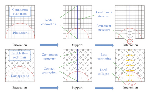
In summary, the method combining DEM and FEM has two remarkable advantages. On one hand, the simulation results can reflect the essential characteristics of continuous deformation and stress of the support structure. On the other hand, the coupled simulation process can clearly reflect the real situation of the interaction between the support and the surrounding rock, and the results are more reliable.
7. Conclusion
- (1)
The unsupported rock above the tunnel face collapses first after tunnel excavation. The further expansion of the collapse cavity caused by the continuous collapse of the upper rock mass enlarges the area of the free face behind the tunnel face, which further leads to a correlated slip of the rock mass in front of the face. It can be seen that the instability of the surrounding rock mass above the tunnel face is the source of the large collapse of the face. Controlling the displacement of the surrounding rock above the tunnel face is the key to preventing large-scale instability of the face.
- (2)
The depth of the collapse risk zone increases exponentially with the increase of the footage, so adopting short footage to excavate the tunnel is an effective way to control the deformation of the weak surrounding rock. The depth of the collapse risk zone under the bench method is 5.33 m, which is about 80% of that under the full section method and the reserved core soil method. The bench method with 2 m cycle footage is the most reasonable excavation method for the tunnel face in carbonaceous phyllite stratum.
- (3)
The displacement of the surrounding rock above the face under the combined support scheme is only about 30% of that with the single support mode. Compared with short bolts, long bolts with advanced small pipes can control the displacement of the surrounding rock more effectively and better prevent the collapse risk of the face at the source. The combined support scheme of advanced small pipes and bolts can control the instability of the tunnel face at the source.
- (4)
The bench excavation method with 2 m cycle footage and the combined support scheme of 4 m small pipes with 8 m bolts was ultimately adopted on-site. As shown in the actual monitoring data, the displacement of the surrounding rock near the tunnel face was effectively controlled, and the maximum vault settlement is 9.81 cm, which meets the engineering requirements.
Conflicts of Interest
The authors declare that they have no conflicts of interest.
Acknowledgments
This work was supported by the National Natural Science Foundation of China (52078428), the Sichuan Outstanding Young Science and Technology Talent Project (2020JDJQ0032), and the Sichuan Science and Technology Program (no. 2021YJ0542). The authors are thankful to the Sichuan Chuanjiao Cross Road and Bridge Co., Ltd., for sharing their data.
Open Research
Data Availability
The data used to support the findings of this study are available from the corresponding author upon request.


