Analysis on Sealing Performance for a New Type of Rubber Olecranon-Shaped Sealing Ring in Pipe Jacking Joint
Abstract
To address the easy damage of rubber sealing rings for pipe joints used in China’s first rock pipe jacking project, the launch of research concerning the optimization design of rubber ring structure was decided. However, modification based on the existing production mold was required, to prevent the construction period and cost from exceeding limits. Utilizing the optimization experience, the stress and waterproof property variations of rubber ring before and after optimization during the pipe translation and deflection were initially analyzed via the ADINA software. Meanwhile, the correct orientation of the ring optimization criteria was confirmed through the field test. Next, the effects of key structural parameters on the contact length and maximum contact pressure of rubber ring were quantified, thereby obtaining the sensitivity correlations between five key parameters of ring optimization to further establish the criteria for rubber ring optimization. The findings of this study offer safe construction suggestions for pipe jacking projects.
1. Introduction
In recent years, pipe jacking technology has gained ever broader applications in water conservancy, municipal works, and energy engineering. Despite these, as the jacking construction continues, new engineering challenges have been encountered successively, one of which is the construction in the artesian aquifer area with damaged rubber rings. After entry into the artesian aquifer, the pipe floats due to hydraulic pressure. This is bound to increase the deflection of preceding and following pipe joints, thereby affecting the waterproofness of rubber joint rings, as well as the safety of construction personnel inside the pipeline.
The rubber ring design is originally intended to ensure the waterproofness of pipe joints. With flexible structure, these rings can limit the joint deflection. The concrete pipe jacking technology is currently mature, and China’s Technical Specifications for Pipe Jacking in Water Supply and Drainage Engineering also provide detailed guidance on the design of pipe joints. Nevertheless, cases with concrete pipes exceeding 3 m in diameter are not common at present, so the suitability of copying the design criteria and experience to the large-sectional ultra-long-distance rock pipe jacking with direct reference to the specifications has not been explored sufficiently.
To solve the failure of hub bearings, a semi-simplified finite element method (FEM) was proposed by Shuai et al. [1] to investigate the sealing performance based on rigid-flexible combined seal groove. With the FEM, the effects of compression ratio, seal groove geometry, O-ring material hardness, and O-ring inner diameter on the Von Mises stress and contact pressure were explored.
Through FE numerical simulations of a compression seal, the rigidity and compressibility of each material in different configurations (temperature, CO2 pressure) were evaluated by Lainéa et al. [2]. To achieve this, a parametric study was carried out to clarify the influence of each parameter under the test conditions.
The extrusion resistance and high-pressure sealing performance of hydrogenated nitrile-butadiene rubber were studied by Chen et al. [3]. It was found that the correlation between critical tear pressure and extrusion gap was greatly important to mechanically design the elastomer seals of oil and gas tools for high-pressure high-temperature (HPHT) applications.
A submarine pipeline stopper used in deep water environment was developed by Zhang et al. [4], and the force, deformation, and sealing performance of the rubber barrel were investigated in each sealing stage. Variations in force distribution, axial/radial displacements, and the stress of five different hardness of rubber barrels during free and contact deformations were analyzed, which thus provides an excellent reference for the research of impermeability and sealing performance.
To sum up, the rubber ring sealing performance has been researched almost always by obtaining the equivalent stress and contact pressure of the rings through experimentation or finite element analysis [5–13]. Given the complex nonlinear contact between the rubber rings and the pipe spigots/sockets during installation, plus the material nonlinearity of rubber materials, the research on the joint sealing design for long-distance large-sectional rock pipe jacking construction is immature. In this context, this study creates the numerical mechanical model of rubber rings via ADINA software after consulting the analytical approaches and research ideas from similar extant studies, with which the stress variations of rubber rings before and after pipe joint installation are discussed, and the sealing performance verification and evaluation are carried out [14].
At the pipe jacking sites, the “eagle beak”-shaped rubber rings with irregular sectional shapes are generally used based on the design experience. Thus, the existing problem is that the rubber rings are easily damaged during installation and jacking to lose waterproofness, which seriously threatens the safety of the personnel inside the pipeline. Three focuses of this study are as follows: how to verify that the rubber rings optimized based on design experience indeed possess better waterproofness? How to mechanically explain the optimization experience? How to determine the key parameter categories of structural optimization and their sensitivities in a systematic and quantitative manner? Only when the above problems are resolved can a reference be provided for similar projects.
2. Joint Numerical Model
2.1. Optimization Criteria for Rubber Rings
- (1)
Since the project construction has already started and the design of jacking pipe structure could not be altered, the geometric size of the newly designed rings must satisfy the space requirements of existing joint groove.
- (2)
To avoid the construction delay and substantial cost increase, the rubber rings were required to be modified on the basis of existing mold.
- (3)
The rubber rings, which were responsible for withstanding the unidirectional medium pressure, should have ever-better sealing performance with heightening pressure. Thus, the basic shape of rubber rings after optimization was still eagle beak.
- (4)
Since the rubber rings were easily deformed due to strong extrusion during installation, the incision was enlarged in the middle part of thicker side of the original rings, to prevent the ring damage resulting from excessive compressive deformation. Besides, the eagle beak rubber rings could also be sectioned for use.
- (5)
Increasing the lateral opening reduced both the installation stress of the rubber rings and the contact pressure on their upper part, which was detrimental to the seepage resistance. Hence, the waterproof contact length in the upper part was increased to improve the impermeability.
Considering both the optimization principles and practical operability of the rubber rings, the numerical approach was initially employed to explore the variation trends of the ring stress and anti-seepage properties before and after optimization.
2.2. Finite Element Model of Rubber Joint Rings
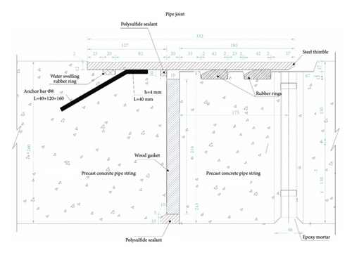
Initially, the structure of pipe joints is described as shown in Figure 1. The joint structure consists mainly of a socket at the tail of preceding pipe, a spigot at the head of following pipe, the flexible wooden gaskets at the ends, a steel thimble anchored in the socket concrete, and two water seal rubber rings bonded to the spigot groove. The pipe joints were also applied with elastic sealing filler (polysulfide sealant). Each wooden gasket, which is 20 mm in thickness, is made up of multiple plywood layers and, in this work, a total of six end-to-end wooden gaskets needed to be arranged on each ring joint surface.
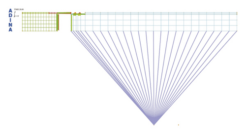
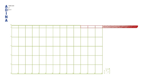
In view of the considerably lower deformation parameters of rubber rings than the steel thimbles and the C50 high-strength concrete for pipe jacking, the research model was simplified into a plane strain model, so as not to increase additional computational cost. The rigid connection method was employed in the model for simulating the translational installation and deflection processes of spigots. Symmetrical and end restraints were imposed on the pipe sockets, while mesh encryption was performed on the steel thimble ends to enhance the convergence of contact computation, as shown in Figure 2.
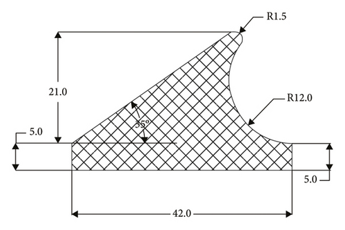
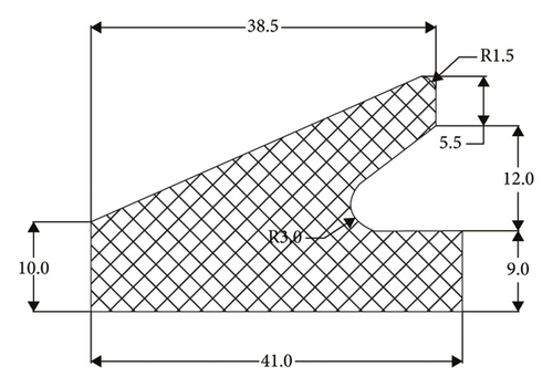
Irregular “eagle beak”-shaped rubber rings were adopted in the present pipe jacking project, whose specific geometric dimensions are detailed in Figure 3(a). The corresponding geometric dimensions of rubber rings after optimization are displayed in Figure 3(b). The type of rubber material is neoprene, with a Shore hardness range of 45–55. The interfaces are flat and smooth without traces, where no cracks are allowed. The rubber rings were bonded into the base groove of pipe insertion part using the neoprene adhesive 202.
2.3. Constitutive Model of Rubber Material
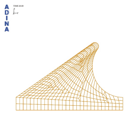
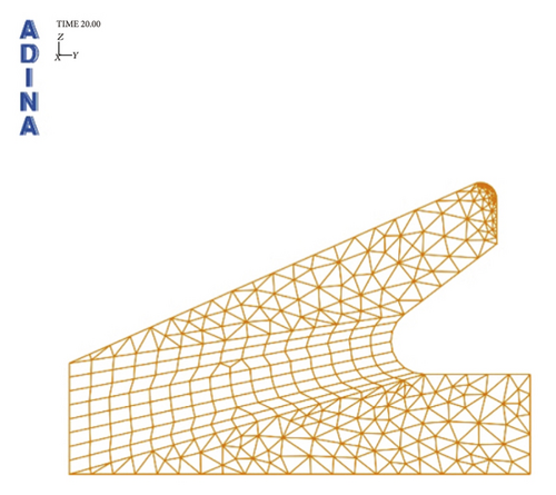
In Table 1, the computational parameters derived based on the Shore hardness of rubber rings are presented. For each joint socket and spigot, four-node plane strain meshes were generated, whereas for the rubber rings and the steel thimble (in contact with the rubber rings), the triangulation method was employed to generate and encrypt the three-node meshes. In Figures 4(a) and 4(b), the meshing diagrams of rubber rings before and after optimization are displayed, respectively. In a similar way, establishing contact relationships was needed between various surfaces of the steel thimble and rubber rings. The contact type was uniformly set as hard contact disallowing penetration among the materials, and a large deformation algorithm was adopted. Besides, considering that lubricating oil was applied during the installation of rubber rings, the friction coefficient between the ring and the joint was set to 0.1. The model computation was divided into twenty steps. The first ten steps were used to simulate the translational installation of joint. In particular, the joint was moved transversely at a constant velocity to a distance of 185 mm within ten computation steps. Meanwhile, the latter ten steps simulated the maximum 2° deflection of the joint.
| Material | Shall hardness | Tensile strength (MPa) | Elongation rate (%) | Shear modulus (MPa) | Poisson’s ratio | C 10 | C 01 |
|---|---|---|---|---|---|---|---|
| Neoprene | 50 | ≥9 | ≥375 | 13.694 | 0.47 | 0.328 | 0.082 |
3. Interpretation of Simulation Results
3.1. Joint Translational Installation Process
3.1.1. Stress Analysis of Rubber Rings
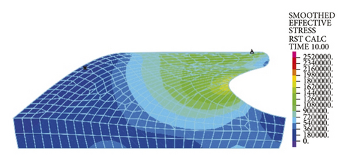
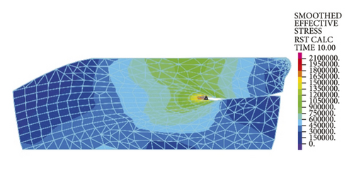
As is clear from Figure 5(a), the maximum stresses of rubber rings are concentrated on the upper surface that is in contact with the steel thimble, with a value of approximately 2.47 MPa. After optimization, the maximum ring stress is reduced to 2.06 MPa, which is located at the self-contact point (Figure 5(b)), exhibiting a decline of equivalent stress by about 20%. At this time, the maximum stress value at the upper contact surface is approximately 1.5 MPa, which is about 40% lower than the initial equivalent stress. These suggest that the optimized structure allows effective reduction in intrinsic stress and has better structural rationality, which can lower the damage probability during installation.
3.1.2. Contact Stress of Rubber Rings
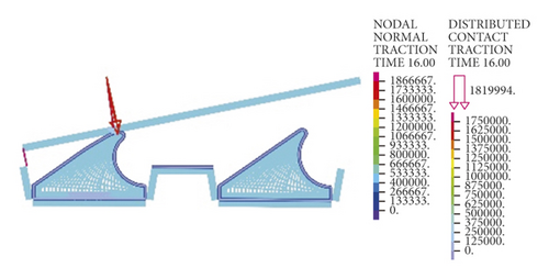
Based on the equivalent stress results, the probability of rubber ring damage seems considerably small, so the ring sealing performance is linked to the safety of the project. Under normal conditions, the sealing performance is considered good as long as the contact pressure generated by rubber ring on the contact surface is higher than the medium pressure. Accordingly, variation trends of contact pressures were analyzed in this section for two different types of rubber rings on various contact surfaces during the translational installation. To better understand the ring sealing performance upon deflection of the joint during and after installation, the contact pressures of contact nodes on the contact surfaces were extracted to establish the correlations of contact pressure with the installation displacement and deflection angle. Figure 6 details the locations and directions of data extraction [16].
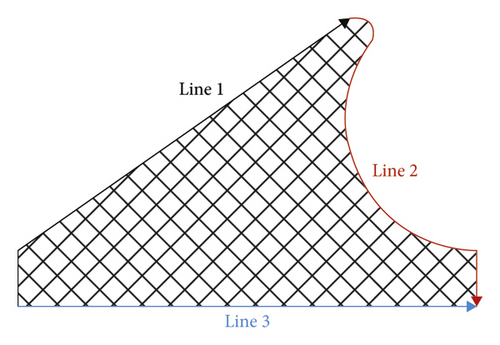
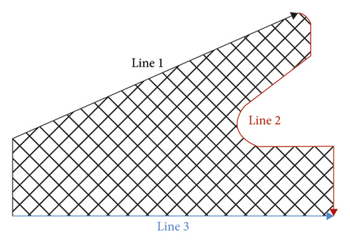
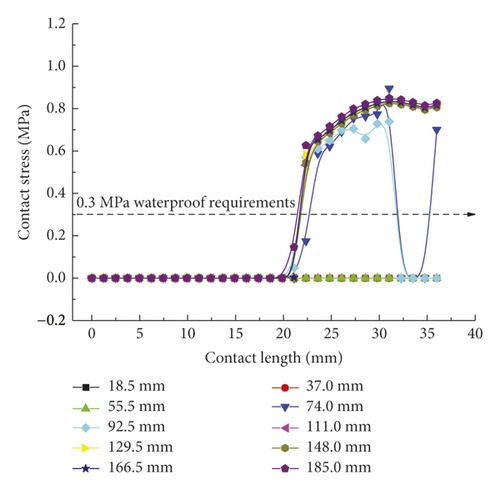
In ADINA, contact computation was implemented using the constraint function, and the relevant computational results served as the interpolation outputs at various contact nodes. Thus, the contact stress concentration at local nodes resulting from complex contact is normal. As shown in Figure 7(a), the rubber ring starts to contact the steel thimble after the pipe spigot is moved by 74 mm. At this time, however, the contact state is unstable, so the stress remains in a fluctuating stage. After the moving distance of the spigot exceeds 111 mm, the first rubber ring is already squeezed into the socket entirely, and the maximum mean contact stress stabilizes at around 0.8 MPa, with a minimum value of not less than 0.6 MPa. This suggests that under the linear installation of pipe joints, the first rubber ring fully conforms to the in situ waterproofing requirements (in this project, the maximum external water pressure was considered to be 0.3 MPa). As is clear from Figure 7(b), the contact stress extraction path for line 2 contains the geometrically highest point of rubber rings before optimization, so the relevant maximum contact stress is as high as 1.8 MPa. Since the rubber rings do not undergo self-contact, no contract force is present within a contact surface range of 4–30 mm. The lower right area of the rings contacts the pipe spigot concrete, and the relevant contact force is just in line with the waterproofing requirements. Regarding the bottom area of rubber rings, since the rings are compressed during forward movement, the contact force in the opposite direction of insertion is estimated to be higher than that in other areas based on the deformation compatibility conditions. As shown in Figure 7(c), the maximum contact force varies within a 0.5–0.9 MPa range. This suggests that the design of rubber rings before optimization fully satisfies the waterproofing requirements in the case of linear pipe jacking.
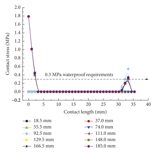
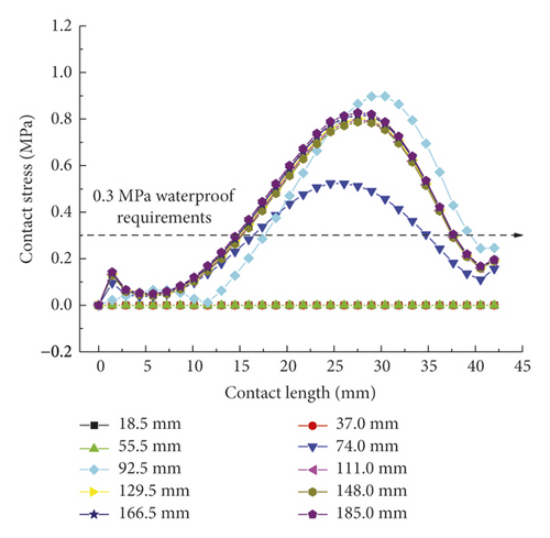
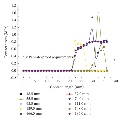
For the second rubber ring, its contact force distribution is similar in trends to the first rubber ring, with the only difference being the presence of time lag effect upon the ring contact. According to Figure 8(a), when the spigot moves to a distance of 129.5 mm, an apparent contact action is produced, although fluctuations remain, with a maximum fluctuating contact stress of up to 1.5 MPa. After full insertion of the spigot into the socket, the contact pressure also enters a stable state, whose maximum value approaches that of the first rubber ring. According to Figure 8(b), the compressive strain of rubber rings is the largest at the geometrically highest point, at which their contact stress is also the largest, far exceeding the waterproofing requirements. In contrast, the distribution trends and values of contact pressures in Figure 8(c) are fundamentally consistent with those of the first rubber ring, suggesting that the design of rubber rings before optimization in the translation process conforms to the waterproofing requirements. The two rubber rings exhibit basically similar deformations.
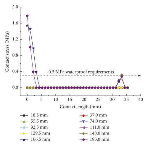
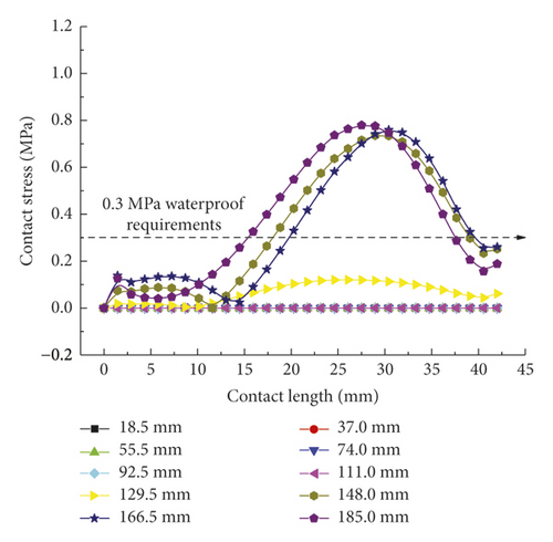
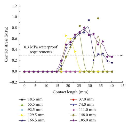
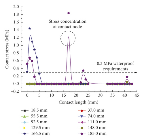
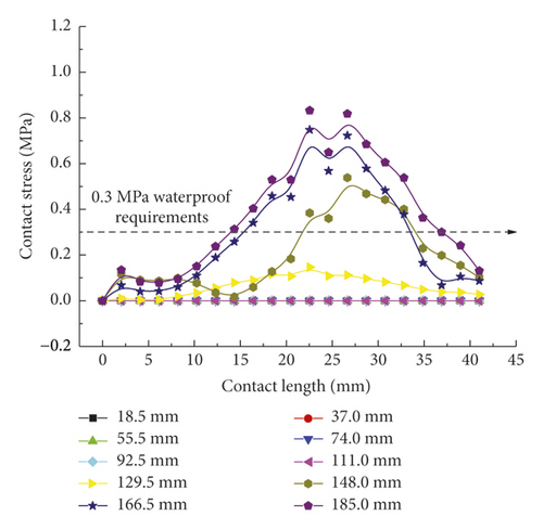
As shown in Figure 9(a), the contact forces of rubber rings after optimization exhibit a “mountain peak” distribution, which is high in the middle and low on the sides. Despite the complete difference from the rubber rings before optimization, the maximum mean stresses are basically maintained at 0.8 MPa. Besides, the effective waterproof contact length for line 1 also increases to 19 mm from the original 11 mm. By appropriately reducing the contact stresses in other contact areas while fulfilling the waterproofing requirements, the probability of structural damage can be lowered, and the effective waterproof contact length can be extended as well, which reflects the remarkable benefits of rubber ring optimization. It is clear from Figure 9(b) that after optimization, the rubber rings produce contact stresses that fulfill the waterproofing requirements just at small displacements of joint assembly, with the maximum stress value being approximately 40% lower than that before optimization. Similarly, as shown in Figure 9(c), the contact forces at the ring bottom before and after optimization are fundamentally identical in magnitude. The difference is that the stress distribution is unimodal before optimization, whereas it is bimodal after optimization. The rubber rings after optimization are safer, are more waterproof, and exhibit approximately 5% longer effective contact length.
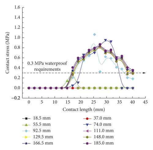
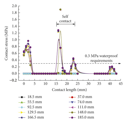
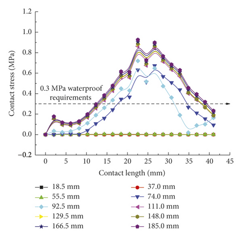
According to Figure 10, the contact pressure curves of the second rubber ring after optimization on various contact surfaces are basically consistent with those of the first rubber ring after reaching stable variations except for the presence of time lag effect. In summary, both rubber rings before and after optimization can meet the waterproofing requirements during the linear installation of pipe joints, although the rubber rings after optimization can attain smaller contact pressures and longer effective waterproof contact lengths. The two ring types exhibit fundamentally identical trends of contact force distribution under the stable stress conditions.
3.2. Joint Clockwise Deflection Process
3.2.1. Stress of Rubber Rings
Since the numerical model is simplified into the problem of analyzing the rigid body plane strain, it is necessary to discuss the stress state of rubber rings upon clockwise and counterclockwise socket deflections separately, as well as the evaluation of waterproofing requirements. The deflection problem is relative; that is, the clockwise deflection of socket can be regarded as a counterclockwise deflection of steel thimble. Accordingly, the clockwise deflection condition is investigated first.
The left and right images in Figures 11–14separately represent the equivalent stresses of the first and second rubber rings for the jacking pipe joints. As is clear from Figure 11, with the slow increase in deflection angle to 0.4°, the equivalent stresses of the two rubber rings also increase due to the constant compression of gap between thimble and socket, where the first rubber ring shows slightly higher stress value than the second rubber ring. With further increase in the deflection angle, the steel thimble is lifted by the front end of socket. At this time, the stresses of rubber rings begin to be released, with far higher stress relief of the second rubber ring than the first one. Accordingly, the second rubber ring is basically in a free state after the deflection angle exceeds 0.8°. Meanwhile, it is not until the deflection angle exceeds 1.2° that the first rubber ring is in an unstressed state.


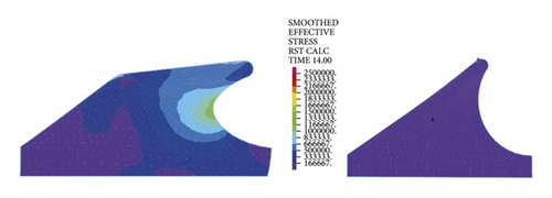


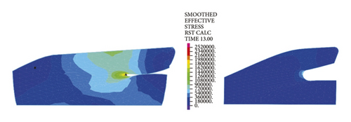
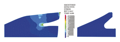


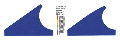


Figure 12 reflects similar trends to Figure 11, where the intrinsic stresses of rubber rings all increase initially and then decrease with the increasing deflection angle, and the stress relief is more evident for the second rubber ring at the same deflection angles. It can thus be inferred that the second rubber ring loses water resistance first during the deflection process. Overall, the stress magnitudes of rubber rings during deflection are considerably lower than the ultimate compressive and tensile strengths. Hence, the research focus is still on the waterproof function of rubber rings upon joint deflection.
3.2.2. Contact Stress of Rubber Rings
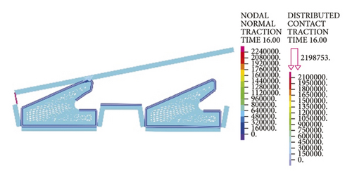
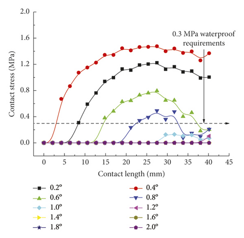
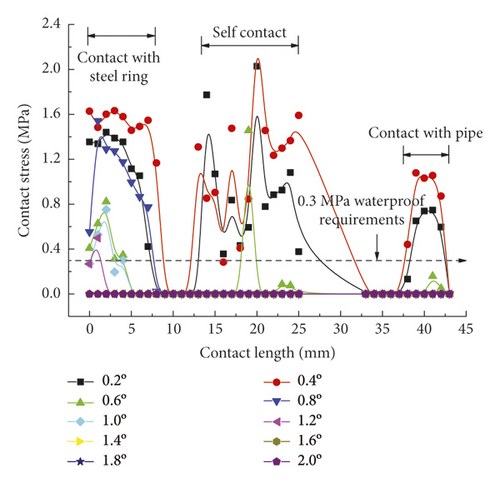
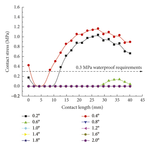
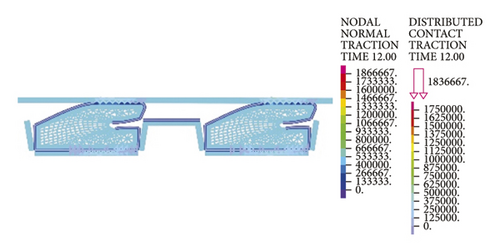
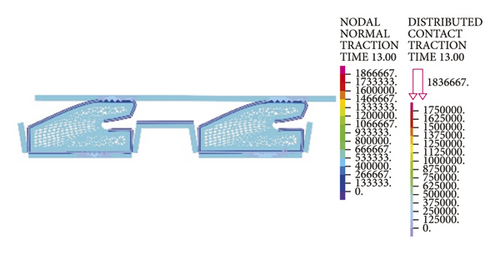
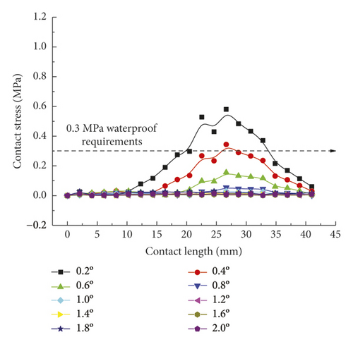
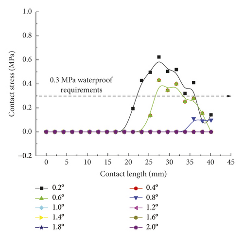
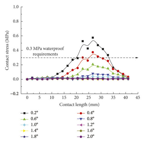
Figure 15 directly reflects the distribution pattern variations of rubber ring contact pressures with the rotation angle, whereas Figure 16 reflects the contact pressure magnitudes of rubber rings on various contact surfaces. According to Figure 16, the distribution pattern of contact pressures fundamentally resembles that in the joint installation process. Line 1 gets the maximum contact stress and effective contact length at a deflection angle of 0.4°; with the increasing deflection angle, the stress and length values show decreases. A 1.0° deflection angle can be considered as the critical deflection angle that fulfills waterproofing requirements. The critical waterproof deflection angle can be as high as 1.2° at the upper part of line 2, while it is only 0.6° at the lower part. The angle value is also only 0.8° at the corresponding bottom part of line 3. Considering that the seepage paths of water flow are merely the top and bottom sites of rubber rings, it can be obtained by combining the analytical results of the upper and lower ring regions that the critical deflection angle of the first rubber ring is 0.8°.
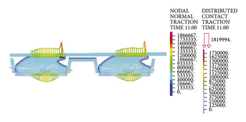
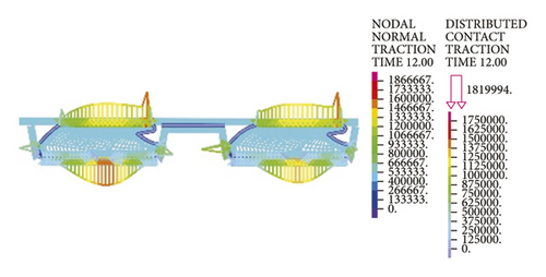
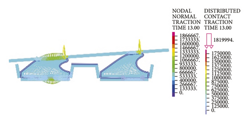
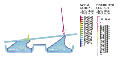
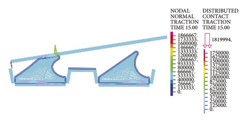
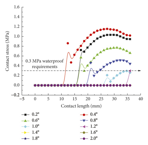
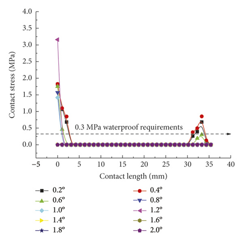
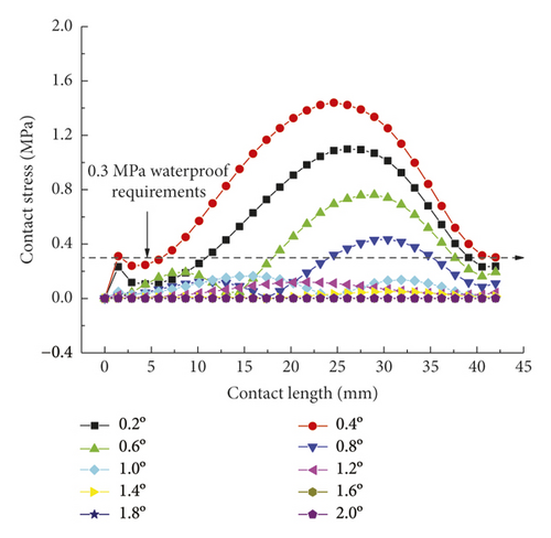
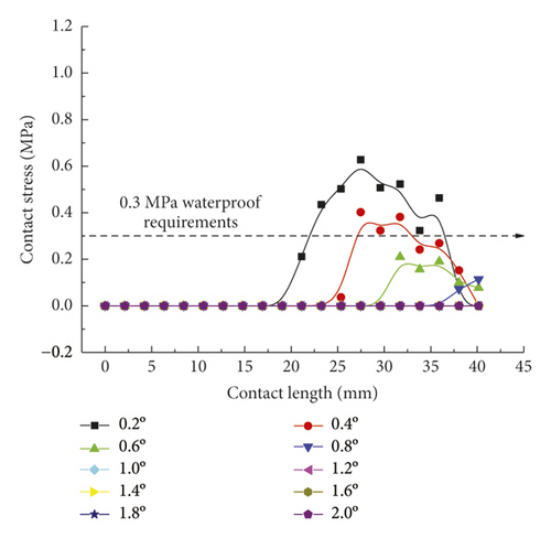
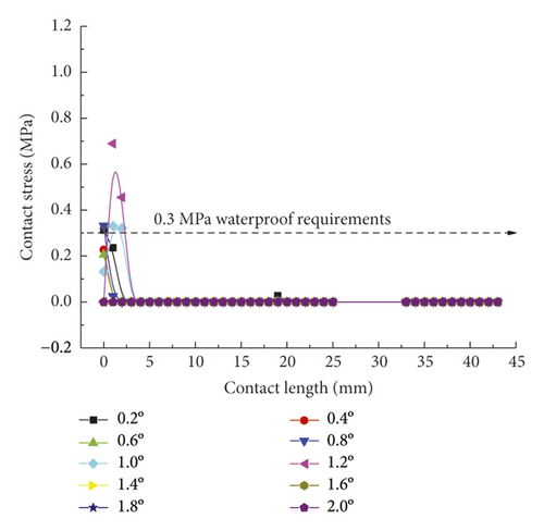
As for the second rubber ring, the contact pressure is absent just at smaller deflection angles. According to a combination of Figures 17(a)–17(c), the critical deflection angle can reach 0.8° at the upper ring part, whereas it is only 0.4° at the bottom ring part, showing a difference of nearly 50%. As a result, the second rubber ring easily loses water resistance upon clockwise deflection of socket. This well reflects the importance of designing two waterproof rings.
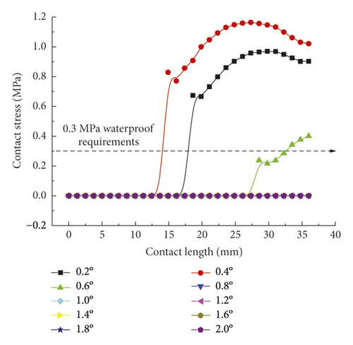
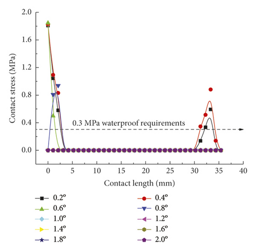
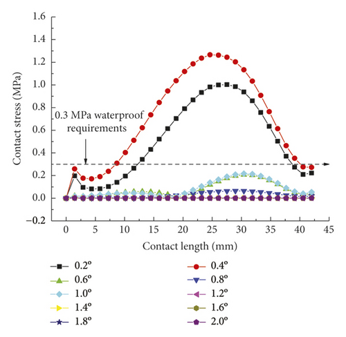
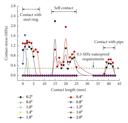
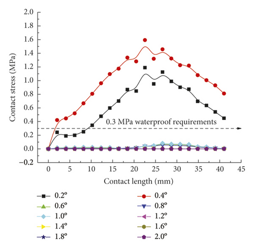
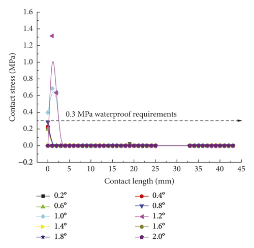
As intuitively illustrated in Figure 18, the contact pressures of rubber rings are the largest when the deflection angle is 0.4°. Subsequently, the steel thimble is detached from the second rubber ring until being detached from both of the rings. As shown in Figure 19(a), the rubber rings after optimization exhibit rather smooth variations of contact pressures, whose values are not lower than those of the pre-optimization ones at deflection angles of 0.2–0.8°. Their effective contact lengths, however, increase markedly. Similar trends are also present in Figures 19(b) and 19(c). There are two major criteria for determining whether the structural optimization of rubber rings is successful: (1) allowing the joints to have a larger deflection angle under the same waterproofing standards; (2) able to attain better waterproof performance at the same deflection angles. Obviously, the evaluation criteria for rubber rings after optimization herein are more consistent with the latter. Hence, after synthesizing the contact pressures on various contact surfaces, the maximum deflection angle of the first rubber ring after optimization remains at 0.8°.
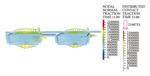
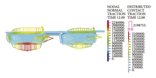
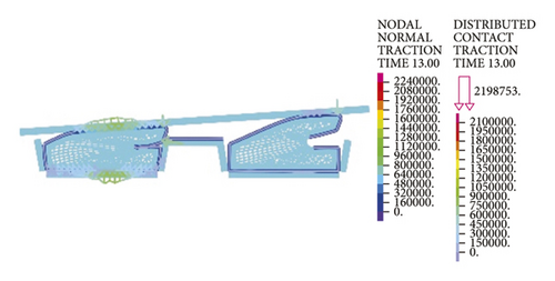
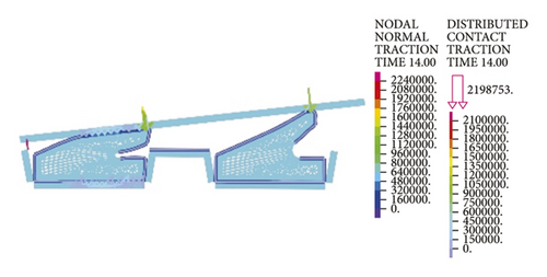
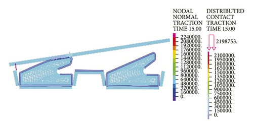

Lastly, it is clear from the results in Figure 20 that the maximum deflection angle of the second rubber ring keeps unchanged before and after optimization. Higher waterproofness is achieved merely by increasing the effective length, which will not be described in detail here.
3.3. Joint Counterclockwise Deflection Process
3.3.1. Stress Analysis of Rubber Rings
A combination of Figures 13 and 14 reveals that during the counterclockwise socket rotation, the difference in stress variations between the two rubber rings decreases markedly as compared to that under the clockwise condition. Both rings are detached from the steel thimble within a deflection angle range of 1.0°. With the continuous increase in deflection angle, the first rubber ring disengages first, so the second rubber ring is the critical point for ensuring the joint waterproofness under the counterclockwise condition. Additionally, it is also clear from the nephogram that the maximum equivalent stresses of rubber rings before optimization are concentrated primarily near the geometrical highest point, while in the case of rubber rings after optimization, the stress concentration is found primarily at the bending point.
3.3.2. Contact Stress of Rubber Rings
As is clear from Figure 21, the contact pressures decrease monotonically with the increasing deflection angle, while the contact stress concentration tends to occur at the geometric maximum point of the rubber rings before optimization. Figures 22 and 23 reveal that the maximum allowable deflection angle of the rubber rings is 1.0° at the top and 0.4° at the bottom, with a difference of about 60%. The maximum allowable deflection angle at the top of the second rubber ring increases to 1.2°, while at the ring bottom, the value remains the same as that of the first rubber ring. The contact pressure at the bottom of rubber rings is lower than that at the top. The contact lengths at the same position of the two rubber rings change insignificantly. The ring bottom is the key area in determining the water permeation.
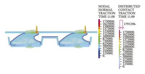
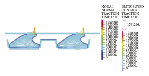
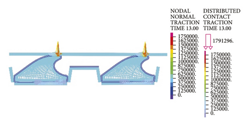
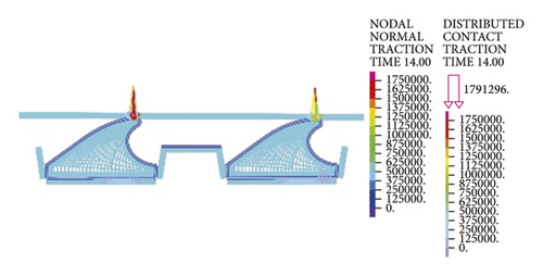
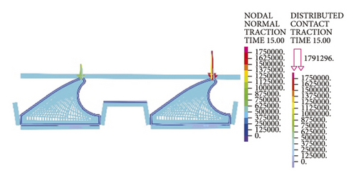
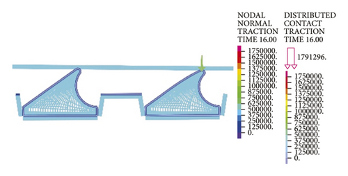
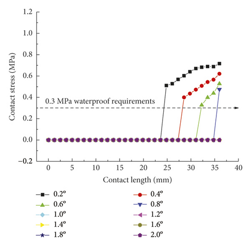
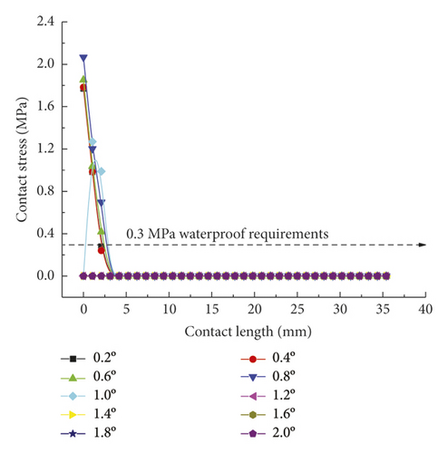
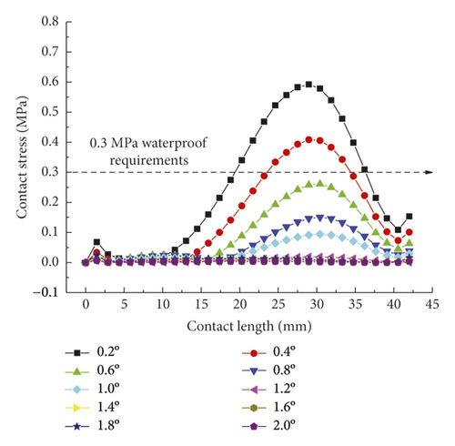
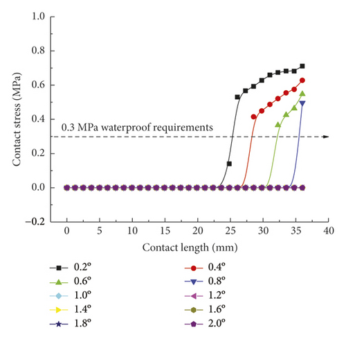
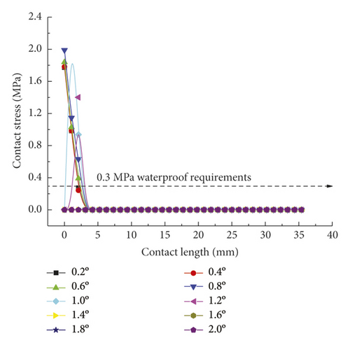
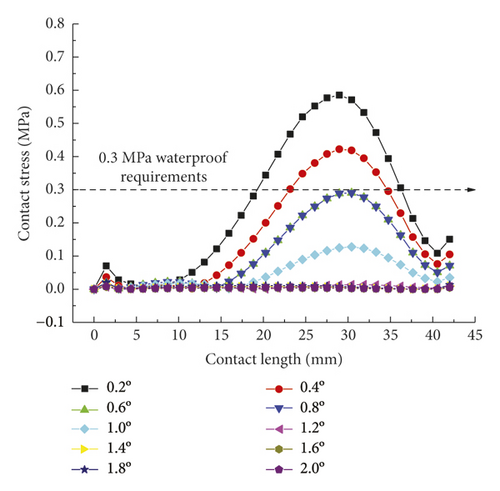
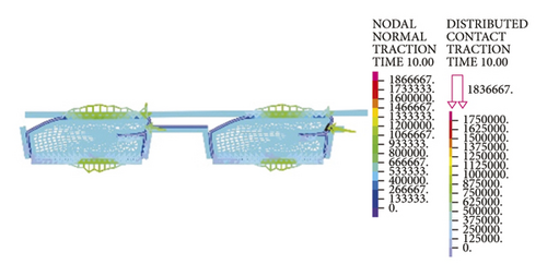
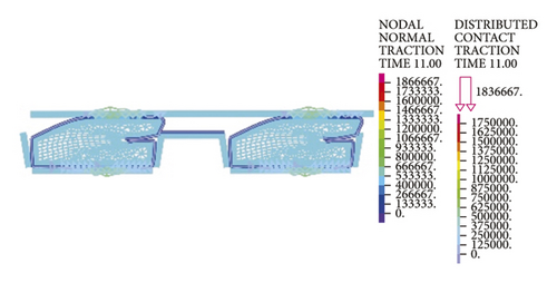
Figures 24-26 indicate that after the optimization, the contact stress distribution of rubber rings is more uniform, and the contact lengths increase slightly. Nevertheless, no significant changes are noted in the deflection angle of the two rubber rings before and after optimization. The bottom region is also a critical area in controlling the joint waterproofness. At smaller deflection angles, the water resistance of joints is little affected.
4. On-Site Pipe Stress Monitoring
4.1. Monitoring Arrangement
To effectively measure the intrinsic stress variations of the two types of rubber rings during installation and construction while avoiding the influences of such factors as spatial locations of measuring points, pipe exterior contact conditions, and jacking force magnitude on the test results, two adjacent pipe joints were selected to perform stress tests simultaneously on the two rubber ring types, as shown in Figure 27. Given the tight construction period, only the second rubber rings were tested according to the actual installation difficulty. Four sets of measuring points were arranged in total. Each set of measuring points comprised two orthogonal strain gauges, of which the circumferential one was used for compensation. Figure 28 displays the arrangement of measuring points.
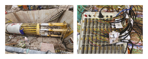
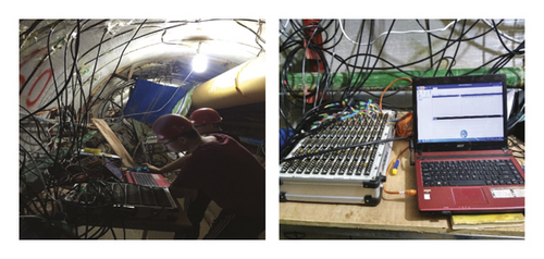
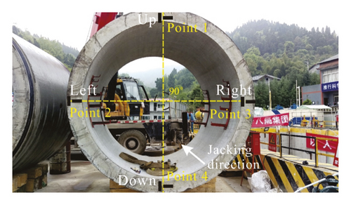
A 60-channel static resistance strain gauge was used as the measuring instrument, whose main technical parameters are listed in Table 2. After the arrangement of monitoring points, an initial inspection was conducted. The channel balances (initial variation ranges ≤15 με) of all the monitoring points were reset.
| Model | Number of measuring points | Sampling rate (Hz) | Measuring range | Sensitivity coefficient | Maximum resolution | Indication error |
|---|---|---|---|---|---|---|
| DH3816N | 60 | 1 | ±19999 με | 1.0∼3.0 | 1 με | <0.5% ± 3 με |
4.2. Analysis of Monitoring Results
Figure 29 displays the intrinsic stress results of the rubber rings during installation and jacking, where BO 1 and AO 1 separately represent before optimization and after optimization at point 1. As is clear from Figure 29(a), the rubber ring stress exhibits a positive correlation with the installation time, except for the corresponding curve fluctuations during the joint installation and adjustment. Due to sensor damage in the installation process, two BO measuring points were lost, while only one AO measuring point was lost, fully suggesting that the ring optimization can significantly reduce the intra-installation damage probability. After proper installation of the joints, the stress values at BO points were all higher than those at the AO points, which again verified the necessity and accuracy of the rubber ring optimization.
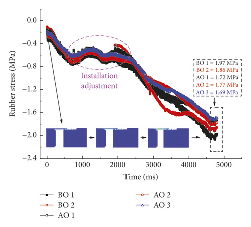
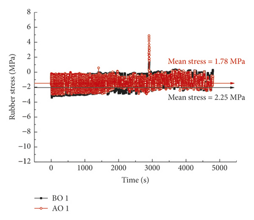
During the pipe jacking, the joint deflects slightly by the action of uneven jacking force, as shown in Figure 29(b). Under the gravitational and deflective actions of the pipes, all the measuring points are damaged except those at the top. Noteworthy is that the damage of measuring points does not imply that the rubber rings are also damaged, since these rings are a superelastic material with a deformation far exceeding that of sensors. However, according to the available test results, the ring stress fluctuates obviously within the 1.5 h of monitoring period. The fluctuation range of the measuring point AO 1 is basically within the envelope line of the point BO 1, and the corresponding mean stress (1.78 MPa) is also lower than that at point BO 1. Thus, the reduction in ring stress can indeed reduce the damage probability under the same conditions, although the accompanying reduction in contact pressure must be strengthened by extending the effective contact length. The field test results are fundamentally consistent with the numerical calculations.
5. The Influence of Rubber Ring Geometrical Parameters on Static Sealing Performance
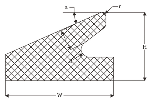
Field tests fully prove the correctness of the ring optimization criteria and the numerical calculation results. Next, it is necessary to further quantitatively explain the effects of the geometric parameter alterations of rubber rings after optimization on the joint seepage resistance, to better understand the numerical calculations in Section 3. As shown in Figure 30, on the basis of optimized ring geometric dimensions, the effects of five parameters, namely contact angle a, chamfering radius r, thickness c, cutting radius R, and Shall hardness HA (under assumed conditions, the specific dimensions of rubber rings after optimization can be determined just by these five parameters) on the static sealing performance, were explored by keeping the upper and lower lip surfaces separately parallel to their upper and lower boundary surfaces while maintaining the joint installation gap, the boundary geometric dimensions (W, H), and the horizontal mapping distance of upper boundary slope unchanged.
5.1. The Influence of Key Parameters on Sealing Performance
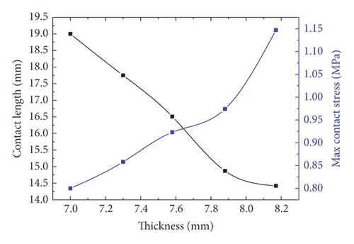
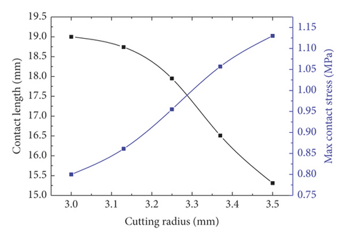
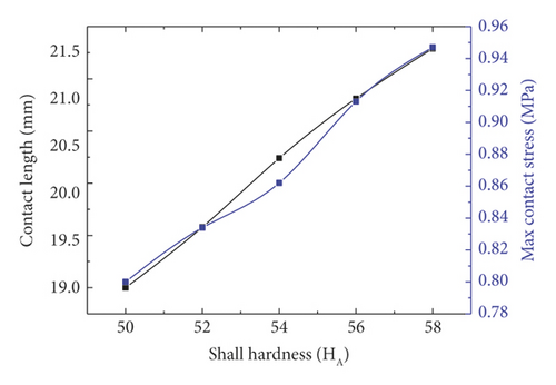
Taken holistically, among the five key parameters in Figure 31, only Shore hardness is positively correlated with the contact length and pressure. It is easily understandable that when the structural shape remains unchanged, greater contact length and pressure are of course more easily attained by enhancing the material strength. Among Figures 31(a)–31(d), only the contact length in Figure 31(b) is positively correlated with the independent variable chamfering radius. Contrastively, the maximum contact pressure is negatively correlated with the chamfering radius.
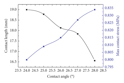
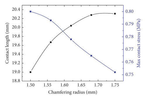
As displayed in Figure 31(a), under constant outer dimensions of rubber rings after optimization, the increase in contact angle indicates corresponding increase in top surface slope. Thus, after being squeezed into fixed-width seams, the contact length will be shortened, and the corresponding contact area will be reduced as well. Consequently, the strain energy received due to extrusion needs to be dispersed in a smaller area, and the contact pressure increases naturally. The top of rubber rings after optimization is the first site under stress in the installation process. Where the chamfering treatment is not performed, stress concentration is highly likely at the sharp corners, resulting in damage and loss of waterproofness. As the chamfering radius increases, the corresponding chamfering circumference increases as well. An increase in contact length or area is conducive to reducing the contact pressure, as shown in Figure 31(b).
Based on the trend shown in Figure 31(c), the upper lip of rubber rings after optimization can be regarded as a cantilever beam structure. According to the material mechanics, the resistance moment of rectangular section is directly proportional to the first power of section width and the square of section height, respectively. Besides, since thickness corresponds to the height direction of deformed section, its increase will result in a markedly enhanced contact pressure. Further, only a smaller contact length is required to withstand the installation stress. Meanwhile, the increase in cutting radius implies that the optimized ring geometry begins to transform towards that before optimization, essentially aiming to reduce the cantilever end length to improve the bending resistance. Finally, it is easy to understand that the higher the shore hardness of rubber, the higher the contact length and the contact pressure, as shown in Figure 31(e).
5.2. Parameter Sensitivity Analysis
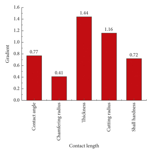
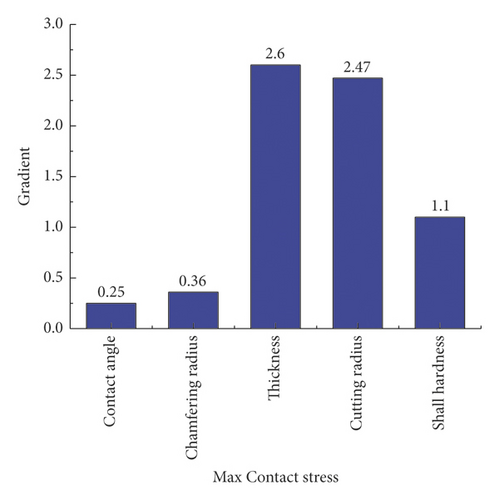
After mechanically explaining the effects of optimized ring geometry on the stress properties, further sensitivity determination of various parameters was required, to guide the optimization of rubber rings. For convenient inter-parameter comparison of sensitivity, the contact angle a, chamfering radius r, thickness c, cutting radius R, and Shall hardness HA were uniformly graded into five levels according to a 16.7% growth rate of their initial values. The growth rate ratio of contact length to contact pressure served as the sensitivity calculation factor.
As displayed in Figure 32(a), the parameter sensitivity rankings responding to the contact length are as follows: thickness > cutting radius > contact angle > Shall hardness > chamfering radius, while the parameter sensitivity rankings corresponding to the maximum contact pressure are as follows: thickness > cutting radius > Shall hardness > chamfering radius > contact angle, as shown in Figure 32(b). Suggestively, the optimization of the ring sealing performance primarily starts from two dominant factors: thickness and cutting radius, which can also be achieved by altering the hardness of rubber material. Although the sensitivity of top chamfer is unobvious given its tiny action zone, the chamfer design is a must in actual engineering, to reduce the damage risk. Meanwhile, the sensitivity of contact angle is reflected primarily in the contact length rather than in the contact pressure, thus fully revealing the mechanism why the rubber rings optimized during the project conforms to the optimization criterion 2.
6. Conclusions
- (1)
During the translational installation of pipe joints, the maximum stress of rubber rings after optimization can be 40% lower than the rubber rings before optimization. This suggests that the rubber rings after optimization are structurally more reasonable, which can reduce the damage probability during installation.
- (2)
The 0.3 MPa waterproofing requirement can be fulfilled by both the pre-optimization and rubber rings after optimization in the translational process.
- (3)
Regardless of the deflection direction of spigots, the effective critical waterproof deflection angles of the two rubber ring types used in the project are basically identical. Nevertheless, the rubber rings after optimization exhibit more uniform contact pressure distribution and longer effective contact length, thereby ensuring the impermeability. In field tests, the number of lost measuring points and the stress monitoring results of rubber rings fully prove the correctness of the numerical calculations and optimization method.
- (4)
Contact angle a, chamfering radius r, thickness c, cutting radius R, and Shall hardness HA can serve as the key parameters for exploring the optimization of eagle beak rubber rings. It is revealed that the Shore hardness exhibits positive correlation with the contact length and pressure.
- (5)
Contact angle, thickness, and cutting radius are negatively correlated with the contact length, while positively correlated with the contact pressure. However, chamfering radius exhibits completely opposite trends to these three parameters.
- (6)
As revealed by the parameter sensitivity analysis of rubber ring optimization, thickness and cutting radius can serve as the dominant determinants for success or failure of optimization, followed by Shore hardness. Meanwhile, chamfering radius is the least sensitive factor, which can though effectively reduce the ring damage resulting from stress concentration. Chamfering treatment is strongly recommended during the rubber ring optimization.
- (7)
The sensitivity of contact angle is reflected primarily in the contact length rather than in the contact pressure, thus fully revealing the mechanism why the rubber rings optimized during the project conforms to the optimization criterion 2. The optimization criteria and ideas herein can provide an excellent reference for similar projects.
Conflicts of Interest
The authors declare that there are no conflicts of interest.
Acknowledgments
This work was funded by the National Natural Science Foundation for Young Scientists of China (52104076).
Open Research
Data Availability
(1) The (field survey, on-site test and laboratory test) data used to support the findings of this study are included within the article. (2) The (origin figures) data used to support the findings of this study are included within the supplementary information file(s).


