Experimental Study on Bearing Capacity of Normal- and High-Strength Steel Screw Anchors
Abstract
In order to study the bearing capacity of high-strength steel screw anchors, six groups of screw anchors with different parameters are carried out in in situ construction and tensile capacity test, and the load-displacement curves of screw anchors with different parameters are obtained. The bearing mechanism, design method, and key design parameters of screw anchors are analyzed. Meanwhile, the test results are compared with theoretical calculation and numerical simulation, respectively. The results show that the drawing capacity of high-strength screw anchor calculated by the existing standard theoretical calculation formula is conservative. The load capacity of high-strength steel screw anchor is significantly higher than that of ordinary strength steel screw anchor. Taking steel strength, buried depth, quantity, distance, and diameter as the influencing factors, parametric analysis is conducted on the uplift capacity of high-strength steel screw anchor in this paper. The embedding depth of screw anchor, the number, spacing, and diameter of anchor plates have significant influence on the drawing capacity of screw anchor. The construction technology of high-strength steel screw anchor is reliable, and the bearing capacity is good, which can be applied in the soft-soil power transmission line projects, such as bog and coastal beach. Meanwhile, the research results can provide reference for the design and construction of screw anchor foundation.
1. Introduction
Foundation design must adhere to the principle of protecting environment and saving resources, according to the line topography, construction conditions, geotechnical engineering investigation data, and comprehensive consideration of foundation type and design scheme so as to achieve the purpose of safety and economic and reasonable foundation design [1]. Screw anchor foundation is mainly suitable for general soil, river, such as mud, coastal tidal flats soft-soil conditions, is a use of deep-soil anchor structure of the role of resistance to the upper structure, composed of a single weak screw anchor plate or one or more pieces of spacing and nonuniform welding in the round or square steel rod or long screw, when using installation of machinery in the top up a torque and spinning it straight into the ground. Manual drilling, mechanical drilling, and other construction methods can be adopted [2–5]. This type of foundation has the advantages of simple manufacturing, convenient installation and construction, fast drilling speed, and fast bearing capacity, can shorten the construction period, reduce the cost of the project, has small damage to the environment, high bearing capacity, and small deformation; screw anchor foundation has unique advantages in these aspects. The earliest use of screw anchors is dated back to Alexander Mitchell in the year 1833 [6]. Around the inner Tidal Bays of England, lighthouses were supported by screw anchors. The highest voltage grade of China’s national high-voltage dc project has reached ±1100 kV [7]. With the development of extra-high-voltage direct current transmission projects towards higher voltage levels and larger transmission capacity, higher requirements will be put forward for the bearing capacity of spiral anchor single pile. In order to study the applicability of screw anchor foundation and promote its application in gravel soil foundation, the axial uplift static load tests of screw anchor full die and half die were carried out in laboratory. The test results show that the overall shear failure and the bearing capacity of the anchor plate in shallow gravel soil tend to be weakened, while the local shear failure of the upper soil and the deformation of the deeply buried anchor plate increase gradually [8–10]. In view of the engineering geological conditions of transmission lines in the hills and mountains of southern Anhui province, which are covered with sandy clay and weathered rock below the soil layer, the environment-friendly straight pillar anchor composite foundation is put forward [11–13]. Screw anchor tilt when drawing strong coupling effect between the horizontal and vertical; the flat circular anchor simulation for this single blade screw anchor in Micronesia sand drawing model experiment by a homemade transparent chamber combined with digital photography measurement technology further reveals flat circular anchor oblique drawing bearing mechanism and effects of various factors [14, 15]. In order to master the nonlinear characteristics of dynamic interaction between steel pipe screw anchor foundation and soil under horizontal excitation, Zhang et al. [16] studied the horizontal vibration response characteristics of steel pipe screw anchor with different anchor geometry in sand based on the self-made model test system of dynamic interaction between anchor and soil. Qian et al. [17], based on the model test in the laboratory, designed and selected two kinds of screw bolt foundation and proposed a method to calculate the ultimate bearing capacity of uplift, which was verified in the field test and proved to be a practical and feasible basic form. Dong et al. [18] studied the failure mode of spiral pile foundation, pile type design, calculation of ultimate bearing capacity of single pile and pile group under ultimate load condition, established the failure mode of its foundation, and deduced the proportional relationship between pitch (blade spacing) and blade diameter, namely, minimum pitch and control pitch. The calculation methods of ultimate bearing capacity of single pile and group pile under different pitch are obtained. The pull-out performance of screw anchor is studied in clay by numerical calculation and clarified the main factors affecting the bearing capacity of the foundation [19–21]. By comparing the results of numerical simulation with those of existing formulas, a method to correct the calculation of pulling capacity on screw anchor foundation is proposed. Zorany et al. [22] adopted the method of experiment and numerical calculation to reveal the influence mechanism of uplift bearing capacity of screw anchor in dense sand by installation disturbance and put forward the calculation method of bearing capacity considering the influence of disturbance. Kwon et al. [23] carried out pull-out test on a single anchor under the action of inclined updraft load. By changing the included Angle between the updraft load and the horizontal direction, the influence law of the inclination of updraft load on the updraft capacity of a single anchor was explained. Due to its unique variable cross section design, the work and load-bearing mechanism of screw piles are more complex than those of common smooth-rod piles.
To sum up, there are many researches on the bearing capacity of ordinary steel screw anchors by scholars at home and abroad, but few literature focus on the bearing capacity of high-strength steel screw anchors. Therefore, it is necessary to carry out researches on the bearing capacity and force mechanism of high-strength steel screw anchors.
2. Screw Anchor Pull-Out Test
2.1. Specimens Design
In this paper, the control variable method is used to analyze the influencing factors of the bearing capacity of high-strength screw anchor. The effects of different burial depths, number of anchor plates, distance between anchor plates, and diameter of anchor plates on the bearing capacity of high-strength screw anchor are compared based on parametric analysis.
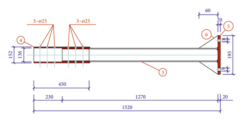
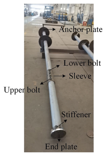
Six kinds of specimens with different specifications were designed to study the influence of different variables on the bearing capacity of single anchor. As we know, steel has excellent mechanical properties at ambient temperature. The normally used mild steel in the paper is Q355. The high-strength steel with a nominal yield strength equal to 420 MPa and 690 MPa is adopted too. High-strength steel offers higher performance in tensile stress, yield stress, bending, weld ability, and corrosion resistance compared to mild steel. Specific parameters are shown in Table 1. The design of specimens is shown in Figure 1.
| Type | Anchor plate | Anchor arm | Depth L (mm) | ||||||
|---|---|---|---|---|---|---|---|---|---|
| Number | Diameter D1 (mm) | Space h1 (mm) | Thickness t1 (mm) | Strength (MPa) | Strength (MPa) | Diameter D2 (mm) | Thickness t2 (mm) | ||
| SY-1 | 1 | φ400 | — | 10 | 355 | 355 | φ133 | 8 | 4500 |
| SY-2 | 2 | φ400 | 1200 | 10 | 355 | 355 | φ133 | 8 | 4500 |
| SY-3 | 3 | φ400 | 1200 | 10 | 355 | 355 | φ133 | 8 | 5700 |
| SY-4 | 2 | φ400 | 1200 | 10 | 355 | 355 | φ133 | 8 | 5700 |
| SY-5 | 1 | φ600 | — | 10 | 420 | 690 | φ127 | 6 | 4500 |
| SY-6 | 2 | φ600 | 1200 | 10 | 420 | 690 | φ127 | 8 | 4500 |


2.2. Engineering Geological Conditions
The soil layer of the site is characterized by silty clay and yellowish brown, wet, plastic soft, no shaking reaction, moderate dry strength and toughness, slightly shiny, and 8.8∼8.9 m thickness.
2.3. Full-Scale Test
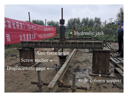
In order to determine the allowable tensile capacity of high-strength steel screw anchors and verify the formulas of tensile capacity, the researchers carried out drawing tests on high-strength steel screw anchors and ordinary strength steel screw anchors in an open field. During the test, a box steel beam was added at the end of the rod head as a reaction beam, and both ends of the reaction beam were supported on the steel pier column. In the middle of the reaction beam, a 50-ton oil pressure jack was placed. The oil pressure jack was firmly connected with the screw bolt head and the load was applied to the screw anchor, as shown in Figure 2.
- (1)
Under a certain level of load, the vertex displacement of pile is 5 times greater than that under the previous level of load, and the total vertex displacement of pile exceeds the predetermined limit displacement.
- (2)
The maximum load has reached the requirement and the settlement of the vertex of pile has reached the relatively stable standard.
- (3)
The pulling amount on the base or anchor pile has reached the allowable value.
- (4)
When the load-displacement curve is slowly deformed, the total displacement of the pile top under vertical load is 60 mm∼80 mm, and that of the pile top under horizontal load is no less than 40 mm. When the pile tip resistance is not fully exploited, the cumulative vertical settlement of pile top can be more than 80 mm, and the cumulative horizontal displacement can be more than 60 mm.
2.4. Test Results and Analysis
2.4.1. Load versus Displacement of Specimens
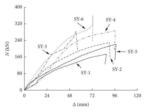
The load-displacement curve of the tensile capacity test of screw anchor is shown in Figure 3. According to the bearing characteristics, it shows that the stress process of screw anchor can be divided into elastic stage and elastic-plastic stage. With the increase of drawing load, the screw anchor position shift gradually increases, and the load and displacement are linearly proportional. This stage is the elastic stage. When the drawing load increases to a certain extent, the screw anchor force enters the elastic-plastic stage, and when the load increases to a small value, the displacement increases obviously, the slope decreases, and the elastic-plastic characteristics are significant. When the number of anchor plates increases, the pulling capacity of screw anchor increases. Compared with SY-1 and SY-2, when the spacing of anchor plates is 1.2 m, the number of anchor plates increases from 1 to 2, and the bearing capacity of screw anchor increases by about 32%. As can be seen from specimens SY-4 and SY-2, when the number of anchor plates remains unchanged, the buried depth increases from 4.5 m to 5.7 m, and the screw anchor bearing capacity increases by about 25%. By comparing SY-6 and SY-2 specimens, it is seen that under the condition that the number of anchor plates and burial depth remain unchanged, increasing the diameter of anchor plates and increasing the strength of steel can significantly increase the bearing capacity of screw anchors. The diameter of anchor plates increases from 0.4 m to 0.6 m, the strength of steel increases from 355 MPa to 420 MPa, and the bearing capacity of screw anchors increases by about 57%.
2.4.2. Torque versus Depth of Specimens
The torque motors that could be used to drive the helical piles into the ground will be relatively quiet, at least when compared with conventional piling, and they could be sited over water or under water. Importantly, the measurement of the torque during installation will provide a quality assurance on the pile capacity, as good evidence exists (from current field measurements and theory) that relates torque resistance to vertical capacity. The design can be further refined from torque data gathered during pile installation, and this might lead to cost savings.
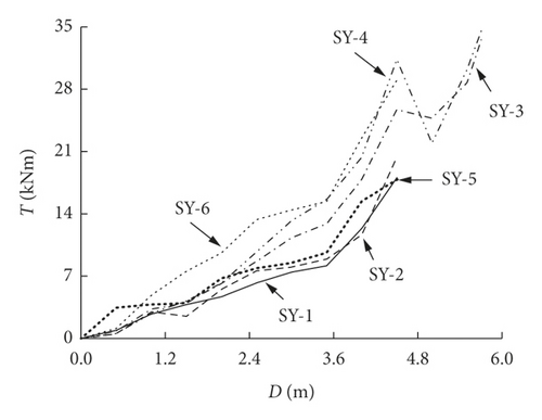
The torque-depth curve of the screw anchor is shown in Figure 4. Seen from Figure 4, the construction torque of screw anchor is related to the buried depth, and the construction torque increases with the increase of the buried depth. By comparing the test results of two specimens, SY-2 and SY-4, both of which are provided with two anchor plates, when the buried depth of screw anchor increases from 4.5 m to 5.7 m, the construction torque increases from 20.4 kNm to 34.5 kNm; in other words, the buried depth increased by 27% and the construction torque increased by 69%. In addition, the number of anchor discs also has an impact on the construction torque value. By comparing SY-1 with SY-2, the construction torque value increases by about 13% when the number of anchor discs is doubled. Similarly, by comparing SY-5 with SY-6, the construction torque value increases by about 63% when the number of anchor discs is doubled. This is because of the high-strength steel used in SY-5 and SY-6. Therefore, comparing SY-2 with SY-6, they both have double anchor plates and the buried depth is 4.5 m. Due to the use of high-strength steel Q420 and Q690 in specimen SY-6, the value of construction torque increases by 43%. It shows that material strength and buried depth have a significant impact on screw anchor construction torque.
3. Theoretical Analysis and Numerical Simulation
3.1. Theoretical Analysis
3.2. Numerical Simulation
In order to verify the superiority of high-strength screw anchor over ordinary screw anchor, the finite software ABAQUS is adopted to establish the overall fine numerical model of screw anchor and surrounding soil. According to the test results of soil samples, the soil model is set as silty clay, and the Moore–Coulomb plastic constitutive model is selected. The specific material parameters are shown in Table 2.
| Soil density (kg/m3) | Modulus (MPa) | Poisson’s ratio | Cohesion (kPa) | Internal friction angle (°) | Expansion angle (°) | Tensile strength (kPa) |
|---|---|---|---|---|---|---|
| 1900 | 2.4 | 0.35 | 35 | 26 | 13 | 40 |
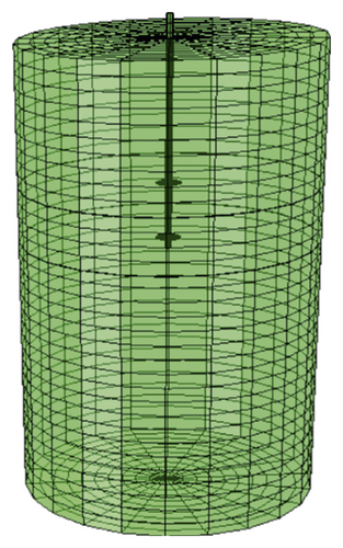
Considering the interaction between soil and screw anchor, the cylinder soil model is adopted in this paper. The height of the cylinder soil model is greater than two times the embedding depth of the bolt, and the diameter is 6 m. For the interaction between screw anchor foundation and soil, the constitutive relationship is a mechanical model with mutual friction. The friction is divided into normal and tangential directions. The normal direction is set as hard contact, the tangential direction is set as penalty contact, and the friction coefficient is 0.3. In the process of setting boundary conditions, two horizontal constraints were set around the soil model and vertical constraints were set at the bottom. Tarawneh et al. [9] conducted field test and numerical simulation of bearing capacity of flat plate screw anchor and spiral plate screw anchor; the calculation results of the two are consistent, and the maximum error of stress value between flat plate anchor model and spiral anchor model is only 5%. Therefore, flat plate screw anchor model is used for analysis in this paper. At the same time, each component of the whole model was assigned element types, and linear geometric order and hourglass control were used to enhance the model convergence.
In this paper, Q355 steel is used for ordinary screw anchor, and two kinds of high-strength steel are used for high-strength screw anchor, namely, Q420 steel for anchor plate and Q690 steel for anchor rod. Ideal elastic-plastic constitutive model is used for all steels. Specific material parameters of each steel model are shown in Table 3.
| Type | Steel density (kg/m3) | Modulus (MPa) | Poisson’s ratio | Yield strength (MPa) |
|---|---|---|---|---|
| Q355 | 7850 | 2.06 × 10⁵ | 0.3 | 355 |
| Q420 | 7850 | 2.06 × 10⁵ | 0.3 | 420 |
| Q690 | 7850 | 2.06 × 10⁵ | 0.3 | 690 |
Figures 5–7, respectively, show the screw anchor soil model, screw anchor model, and screw anchor stress distribution. As can be seen from the screw anchor stress distribution cloud diagram in Figure 6, the stress at the connection between screw anchor plate and bolt is large, while the stress at the overhanging part of anchor plate is small. The stress gradually decreases from the connection point to the overhanging edge of anchor plate. The stress value of anchor plate closer to the ground is generally larger than that of the lower anchor plate.


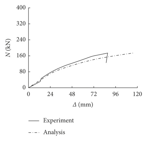
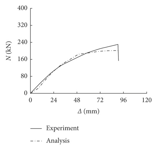
Comparison of load-displacement curves between test and numerical simulation is shown in Figures 8(a)–8(f). It can be seen from Figures 8(a)–8(f) that the numerical simulation is in good agreement with the test load-displacement curve. At the beginning, the vertex displacement of the screw anchor increases with the increase of the drawing load and presents a linear ratio relationship. When the load increases to a certain value, the load value increases slightly but the displacement increases rapidly, as shown in Figures 8(a), 8(b), and 8(f). Therefore, soil model, screw anchor model, and unit division are reasonable in numerical simulation, which can provide reference for parametric analysis of uplift capacity of high-strength steel screw anchor.
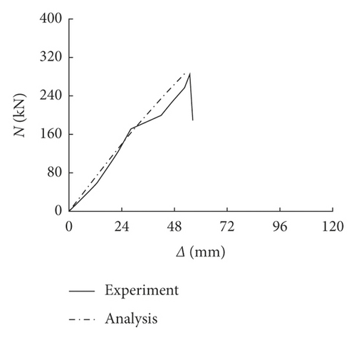
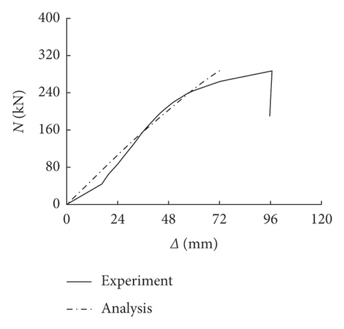
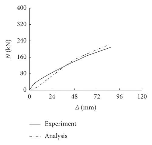
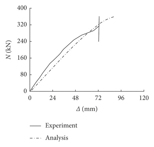
The comparison of theoretical calculation, numerical calculation, and experimental results is shown in Table 4. As seen from Table 4, for mild steel screw anchor specimens, the bearing capacity results of theory are similar to the numerical and experimental results. But for the high-strength steel screw anchor specimens, the theoretical results are different from the numerical and experimental results. It is shown that the bearing capacity of steel screw anchor calculating by theory formula is not suitable for high-strength materials. Besides, with the capacity of specimen rising, the resilience rate is higher too.
| Type | Theoretical results (kN) | Numerical results (kN) | Experimental results (kN) | T/E | N/E | Resilience rate (%) |
|---|---|---|---|---|---|---|
| SY-1 | 160 | 170 | 174 | 0.94 | 0.98 | 10 |
| SY-2 | 221 | 223 | 230 | 0.96 | 0.97 | 13 |
| SY-3 | 310 | 315 | 285 | 1.09 | 1.11 | 19 |
| SY-4 | 265 | 281 | 287 | 0.92 | 0.98 | 14 |
| SY-5 | 170 | 218 | 222 | 0.77 | 0.98 | 20 |
| SY-6 | 285 | 355 | 360 | 0.79 | 0.99 | 17 |
3.3. Parametric Analysis
-
Steel strength (fy): 355 MPa, 390 MPa, 420 MPa, 460 MPa, 550 MPa, and 690 MPa
-
Anchor plate buried depth (h): 4.5 m, 5.5 m, 6.5 m, 7.5 m, 8.5 m, 9.5 m, and 10.5 m
-
Anchor plate number (n): 1, 2, 3, 4, and 5
-
Anchor plate spacing (l): 0.6 m, 1.2 m, 1.8 m, 2.4 m, and 3 m
-
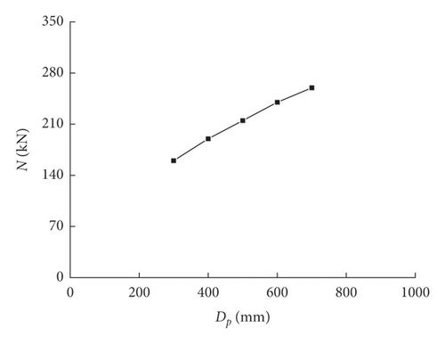
Anchor plate diameter (Dp): 0.3 m, 0.4 m, 0.5 m, 0.6 m, and 0.7 m
3.3.1. Steel Strength
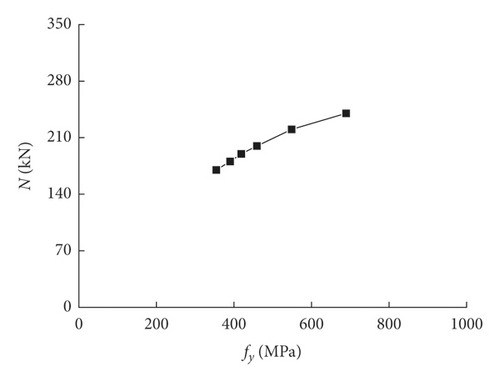
The basic situation of the calculation example is as follows: the buried depth of anchor plate is 4.5 m, the number of anchor plate is 1, the diameter of anchor plate is 0.4 m, the thickness of anchor plate is 10 mm, the diameter of anchor bolt is 133 mm, and the wall thickness of anchor bolt is 8 mm. The influence of steel strength on the bearing capacity of screw anchor is shown in Figure 9. The drawing capacity of screw anchor increases with the increase of steel strength, the steel strength increases from 355 MPa to 390 MPa, the strength increases by 10%, the bearing capacity of screw anchor increases by 6%, the steel strength increases from 550 MPa to 690 MPa, the strength increases by 25%, and the bearing capacity increases by 9%. It is seen that when the steel strength increases to a certain extent, the contribution of the steel strength to the uplift capacity of the screw anchor decreases, because when the steel strength increases to a certain value, soil conditions become the main factors affecting the bearing capacity of the screw anchor.
3.3.2. Buried Depth of Anchor Plate
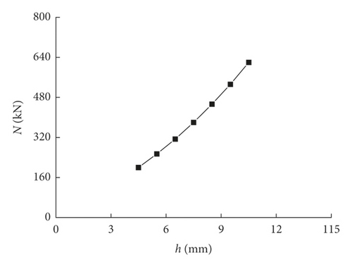
The basic situation of the calculation example is as follows: steel strength 690 MPa, anchor plate number 1, anchor plate diameter 0.4 m, anchor plate thickness 10 mm, anchor bolt diameter 133 mm, and anchor bolt wall thickness 8 mm. Figure 10 shows the influence of anchor plate burial depth on the bearing capacity of screw anchor. When the buried depth of screw anchor plate increases from 4.5 m to 5.5 m, the buried depth increases about 22% and the uplift capacity of screw anchor increases about 27%. When the buried depth of screw anchor plate increases from 9.5 m to 10.5 m, the buried depth increases about 11% and the uplift capacity of screw anchor increases about 17%. It is seen that the pull-out bearing capacity of screw anchor increases with the increase of the buried depth of screw anchor plate, which has a significant influence on the pull-out bearing capacity of screw anchor.
3.3.3. Number of Anchor Plates
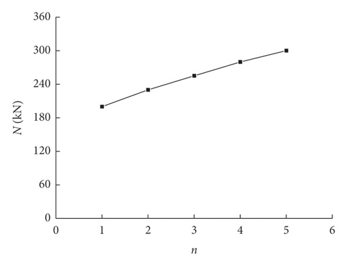
The basic information of the calculation example is as follows: steel strength 690 MPa, anchor plate buried depth 4.5 m, anchor plate diameter 0.4 m, anchor plate spacing 0.5 m, anchor plate thickness 10 mm, anchor bolt diameter 133 mm, and anchor bolt wall thickness 8 mm. The influence of the number of anchor plates on the bearing capacity of screw anchors is shown in Figure 11. When the number of screw anchors increases from 1 to 2, the bearing capacity of screw anchors increases about 15%. When the number of screw anchors increases from 4 to 5, the bearing capacity of screw anchors increases about 7%. It is seen that the pull-out bearing capacity of screw anchor increases with the increase of the number of anchor plates, but not the better, and the increase rate of bearing capacity decreases with the increase of the number of anchor plate.
3.3.4. Anchor Plate Spacing
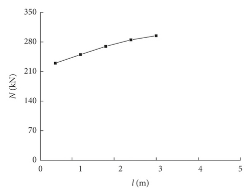
The basic situation of the calculation example is as follows: steel strength 690 MPa, anchor plate buried depth 4.5 m, anchor plate number 2, anchor plate diameter 0.4 m, anchor plate thickness 10 mm, anchor bolt diameter 133 mm, and anchor bolt wall thickness 8 mm. The influence of anchor plate spacing on the bearing capacity of screw anchor is shown in Figure 12. When the spacing of anchor plates increases from 0.6 m to 1.2 m, the uplift capacity of screw anchors increases by about 9%; when the spacing of anchor plates increases from 2.4 m to 3.0 m, the uplift capacity of screw anchors increases by about 3.5%. It shows that when the distance between anchor plates increases appropriately, the pulling capacity of screw anchor increases with the increase of the distance between anchor plates. If the distance between anchor plates is too large, the cooperative working capacity between anchor plates deteriorates. Therefore, the pulling capacity of screw anchor decreases.
3.3.5. Diameter of Anchor Plate
The basic situation of the calculation example is as follows: steel strength 690 MPa, anchor plate buried depth 4.5 m, anchor plate number 1, anchor plate thickness 10 mm, anchor bolt diameter 133 mm, and anchor bolt wall thickness 8 mm. Figure 13 shows the influence of anchor disc diameter on the bearing capacity of screw anchor. When the diameter of anchor plate increases from 0.3 m to 0.4 m, the pull-out bearing capacity of screw anchor increases by about 19%, and when the diameter of anchor plate increases from 0.6 m to 0.7 m, the pull-out bearing capacity of screw anchor increases by about 8.3%. It is seen that the pull-out bearing capacity of the screw anchor increases with the increase of the diameter of the anchor plate. Too large diameter of anchor plate will cause local stability problem of anchor plate itself, and too large diameter to thickness ratio will reduce the pulling capacity of spiral anchor.
4. Conclusions
- (1)
The bearing capacity of high-strength steel screw anchor increases significantly compared with that of normal-strength steel screw anchor, and the rebound rate is larger after unloading.
- (2)
Parametric analysis of the uplift capacity of spiral anchors shows that steel strength, buried depth, and number of anchor plates, distance between anchor plates and diameter of anchor plates are the main influencing factors of bearing capacity of spiral anchors, among which the buried depth of anchor plates has the most significant influence on tensile bearing capacity of spiral anchors.
- (3)
The tensile bearing capacity of high-strength screw anchor calculated by the theoretical formula in the existing code is small, which needs to be modified by the calculation formula of uplift bearing capacity.
Conflicts of Interest
The authors declare that there are no conflicts of interest regarding the publication of this article.
Acknowledgments
The research work described in this paper is part of Project 51908340 supported by the National Natural Science Foundation of China and Project ZR2021ME190 supported by Natural Science Foundation of Shandong Province of China.
Open Research
Data Availability
The data used to support the findings of this study are currently under embargo while the research findings are commercialized. Requests for data, 6/12 months after publication of this article, will be considered by the corresponding author.


