Comparing Numerical Results for Seismic Performance of Portal Steel Frames Braced with Steel: HSS Brace, Glulam Timber Brace, and Timber-Steel-BRB
Abstract
This study involves the application of timber-based bracings elements. For this purpose, seismic analyses are performed on special portal steel frames without the brace and diagonally braced with Glued Laminated Timber (glulam) and Timber-Steel Buckling Restrained Brace (TS-BRB), and the results are compared with the same configuration using steel Hollow Structural Sections (HSS) bracing, using OpenSees structural analyzer. First, to verify the accuracy of the modeling, the numerical results are compared with experimental measurements on several types of elements: (a) diagonally braced frame with steel Hollow Structural Sections with a concentrically steel braced frame which was tested by the quasi-static method under cyclic loading protocol by previous researchers, (b) diagonally glulam braced frame with results of shake table tests on single-story timber braced frames, and (c) Timber-Steel Buckling Restrained Brace (TS-BRB) frame with experimental results of Heavy Timber Buckling-Restrained Braced Frame (HT-BRB). In the second step, the aforementioned timber base bracing alternatives (glulam, TS-BRB) are applied in the special portal steel frame, then the seismic performance of the frame is investigated under pushover, cyclic, time history, and incremental dynamic analysis (IDA), and then the results are compared with the behavior of similar portal frame in two conditions without the brace and diagonally braced with the steel-HSS brace. Results showed that steel-HSS, glulam, and timber-steel buckling restrained braces have significant roles in energy dissipation, increasing shear capacity, decreasing interstory drift, and decreasing weight and cost of estimation of the structure.
1. Introduction
Since experimental tests on steel frames are very time-consuming, numerical modeling is a suitable alternative to expensive laboratory tests, especially in the field of steel frame research. Nowadays, researchers have access to various software packages such as ABAQUS, ANSYS, and OpenSees. To understand the physical performance, many researchers have performed numerical modeling using OpenSees platforms. Seismic performance is described by designating the maximum allowable damage state for an identified earthquake ground motion. Performance objectives such as life safety, collapse prevention, and immediate occupancy are used to define the state of the building following a design earthquake. It is necessary to design steel frames to perform well under seismic loading. It has been observed that steel frames without bracing perform poorly in severe earthquakes. The seismic performance of steel frames can be improved by using different types of steel and wooden bracing. Steel braces have been used since ancient times and a lot of research has been done on them. Nowadays, researchers also use wood and hybrid wood-steel bracing for frames that performed poorly in severe earthquakes. Moore [1] reported details of the structural design of a 12-story studio building constructed in Auckland, New Zealand. The building’s earthquake-resistant system consisted of traditional concentrically braced steel frames (CBF), while the floor system consisted of 65 mm thick glulam panels bonded to gypsum board. Gilbert et al. [2] proposed a hybrid system of glulam frames and buckling restrained steel braces (BRBs) to avoid damage to the connections between timber members. The authors performed a nonlinear dynamic analysis (NLDA) on a plane model of a 6-story ideal building constructed with the new system and a moment-resisting steel frame. Gilbert et al. [3] proposed the integration of glulam frames with friction-reducing steel struts. The authors performed quasi-static and pseudodynamic unidirectional tests on a half-scale subassembly consisting of a wood beam-column connection and steel braces with friction dampers connected by a steel connection and glued-in bars. Timmers et al. [4] performed modal spectral analyses with numerical models for the hybrid timber structure, which consisted of steel-BRB braced chevron frames and glulam columns. The frame was designed to allow the BRBs to yield in tension and compression and dissipate seismic energy. Bracing may be provided to increase the response of the structure to lateral loading and to provide good ductility characteristics for good performance under seismic loading. Frame and braces form a vertical truss, and lateral loading is resisted by the action of the truss. The bracings allow the system to achieve a significant increase in lateral stiffness with minimal additional weight. As a result, they increase the natural frequency and usually reduce the lateral displacement. As a result of the inelastic effect of the bracing, they develop ductility. In the cyclic analysis under seismic loading, there is a deterioration in the strength of the structural members. These are significant properties of frame members under cyclic loading, which leads to a reduction in deformation capacity. Cyclic analysis is proposed to determine the seismic requirements for structures that consider the cumulative damage under cyclic loading. In seismically active regions, it is generally not economically feasible to design conventional structures to remain resilient during severe earthquake motions. Fortunately, this may not be necessary if it is possible to take advantage of the ability of several types of structures to dissipate energy through inelastic action. In addition, fragility curves play an important role in estimating the vulnerability of structures. Seismic fragility of structures describes the probability of damage due to random ground motions. An alternative is to use analytical methods such as incremental dynamic analysis (IDA) to develop the fragility curves for different structures. Pushover analysis is an analysis method in which the structure is under lateral force with an invariant height distribution until the target displacement is reached. The displacement is plotted with the base shear to obtain the static pushover curve. With the help of pushover analysis, we obtain the shear capacity of the structure and this analysis helps us to determine the formation of the first plastic hinge, according to which we can study the behavior of the structure after the formation of the first plastic hinge. For design or evaluation purposes, the seismic capacity of the structural system for different seismic hazard levels can be calculated by nonlinear time history analysis using several properly selected ground motions. Ground motion selection plays a crucial role in seismic analysis. This study is divided into three steps: In the first step, the macro element modeling approach using OpenSees of portal steel frames is presented, and details of various simulations are discussed. In the second step, the models are studied under pushover, cyclic, time history, and IDA analyses. In the third step, the results are discussed and concluded. The purpose of this analysis was to compare the capacity curves before and after bracing and also to compare the hysteresis curves which show earthquake energy dissipation and to reduce the maximum interstory drift by using different types of timber base bracing.
2. Numerical Modeling Framework
The modeling approach of portal steel frames in OpenSees has presented four portal steel frames in this section: portal steel frame without bracing, portal steel frame with bracing of glulam, portal steel frame with bracing of hollow steel sections (HSS), and portal steel frame with bracing of hybrid wood-steel buckling braces (TS-BRB). Details of the specimens and material properties are given in Tables 1–3, respectively.
| Modulus of elasticity (MPa) | Shear modulus (MPa) | Poisson ratio |
|---|---|---|
| E R = E3 = 949 | G RT = G32 = 119.3 | V LR = V13 = 0.331 |
| E T = E2 = 488 | G LR = G13 = 819 | V LT = V12 = 0.406 |
| E L = E1 = 10844 | G LT = G12 = 656 | V RT = V32 = 0.6 |
| V TR = V23 = 0.331 | ||
| V RL = V31 = 0.037 |
| Type of frames | Members | Fy (MPa) | Modulus of elasticity (MPa) |
|---|---|---|---|
| Steel-HSS braced frame | Beams and columns | 275 | 200000 |
| Steel brace | 275 | 200000 | |
| Gusset plates | 275 | 200000 | |
| Unbraced Frame | Beams and columns | 275 | 200000 |
| Glulam braced frame | Beams and columns | 275 | 200000 |
| Gusset plates | 275 | 200000 | |
| Timber-steel-BRB | Brace core | 248 | 200000 |
| Specimen | Material | Section (mm) | A (mm2) |
|---|---|---|---|
| Frames columns | Steel | IPE200 | 2850 |
| Frames beam | Steel | IPE200 | 2850 |
| Timber base brace | Glulam | (100 × 100) | 10000 |
| Steel-HSS brace | Steel | HSS (60 × 60 × 3) | 674 |
| TS-BRB core | Steel | (50 × 20) | 1000 |
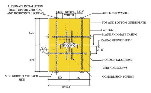
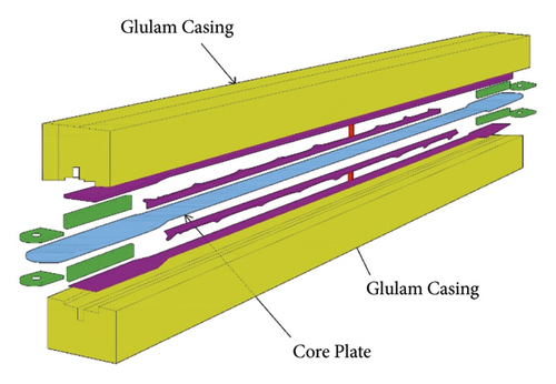
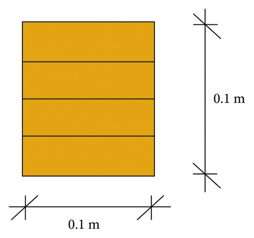
Three types of braces have been used. The first type of brace has a hollow steel cross section and the second type of the brace is a hybrid buckling restrained brace with a steel core confined by glulam timber as shown in Figures 1 and 2, and the third type is an ordinary glulam brace whose section is shown in Figure3. In hybrid timber-steel buckling restrained brace (TS-BRB) screws mechanically strengthen the brace assembly together, glulam timber casing is to resist global buckling, and the steel core plate at the unboned internal interfaces is to resist higher mode buckling; final assembly of the specimens consisted of mechanically laminating the glulam and steel core plate assembly together with 3/8 in (9.5 mm) diameter fully high tensile strength screws. The dimensions of the groove in each section of the glulam casing that houses the core plate required a tight control on tolerances. To obtain this, the glulam specimens were made on a five-axis CNC mill that achieved a tolerance of 0.04 in (1 mm) in both depth and width of the groove. The main central plate is cut to its profiled shape using a CNC plasma cutter. The cut main plate has to be free of notches and defects, and, within the yielding core, length has a surface roughness not-to-exceed 1000 μin (25.4 μ) [6].
2.1. FEM Modeling
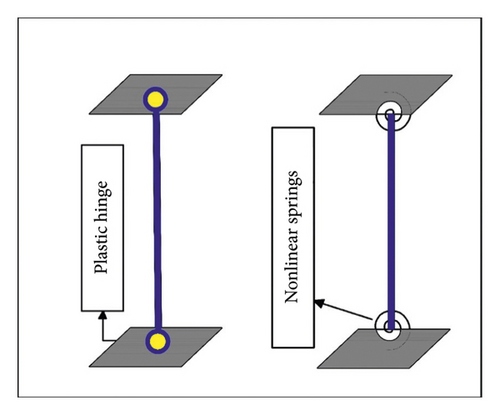
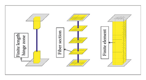
OpenSees is capable of simulating the response of structural systems subjected to earthquakes via FEM. In OpenSees, structural elements can be introduced at the element level, sectional level, and fiber level by introducing different relations, force-axial strain/moment-curvature relations, and stress-strain curves, respectively. In the following, the various macroelement modeling steps of the special portal steel frame in OpenSees are described. Here are two general numerical methods for the investigation of the nonlinear behavior of special portal frame members in OpenSees: The first one is to use concentrated plasticity by zero length elements which work as rotational springs to represent the structure’s nonlinear behavior as shown in Figure 4. The rotational springs capture the nonlinear behavior of the frame; the springs employ a bilinear hysteretic response based on the modified Ibarra-Krawinkler deterioration model. The second approach is to use distributed plasticity as shown in Figure 5. In this method, the plasticity is distributed over a defined length. The related responses of each plastic hinge area are defined as separate sections. The axial response is specified by an elastic section, while the flexural response is defined by a uniaxial section using two-line material based on the modified Ibarra-Krawinkler model. The rotational performance of the plastic hinges in models follows hysterical response based on the updated Krawinkler model [7], which is derived from an extensive database of steel component tests. Alternatively, these input parameters can be determined using approaches similar to those described in FEMA 356.
2.1.1. FEM Modeling of Timber-Based Glulam Bracing
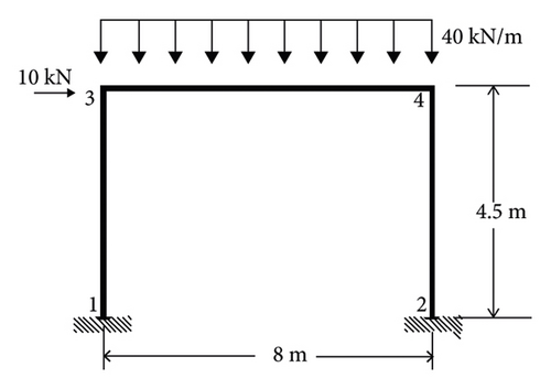
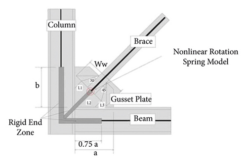
The model in this study is a single-story special portal steel frame, braced with a timber based glulam brace. In this study, first the beam and columns nonlinear behavior is represented using the concept where the plastic behavior occurs over a finite length. The brace’s nonlinear behavior is represented using the concentrated plasticity concept with rotational springs. The models are assumed to be located in Tehran according to the earthquake zoning map of Iran, in a region with relatively high risk, and the ground acceleration of the earthquake is 0.35 in soil type C. In models, the width of the frame is 8 meters, and the height of the frame is 4.5 meters as shown in Figure 6. Criteria of analysis and design were considered by ASCE-7 with the requirements of FEMA P-695. The modeling of the gusset plates was performed using the rotational hinge method introduced by Po-Chien Hsiao et al. [8]; in the proposed method, the connections of the beams to the column are considered moment-resistant and, at the end of the beams, the top and bottom of the columns, and also at the two ends of the brace, rigid offsets (elastic element with high stiffness) are introduced. These rigid areas at the end of the members are then connected to the main members by rotational springs as shown in Figure 7. The connections of the columns to the foundation are rigid. Simulations were performed using OpenSees software for modeling of the beams and columns, and the nonlinear beam-column element with the plasticity in the length of element (with five integration points along the element) and fiber cross section were used. In the models, the effect of the dead and live loads are nodal masses at the joint of beams and columns mx = 2250 kg for nodes 3 and 4.
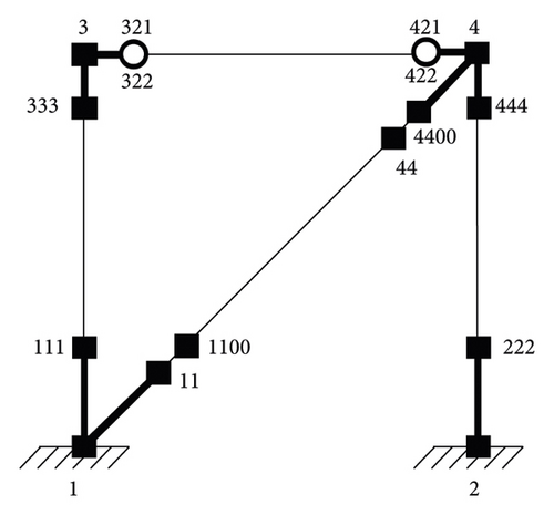
All analyses are performed in two dimensions in OpenSees model for analysis which is shown in Figure 8. The frame is analyzed under gravity loads before the pushover, cyclic, time history, and IDA analysis are conducted. For modeling glulam brace in OpenSees elastic elements with uniaxial material elastic are used [9].
2.1.2. FEM Modeling of Timber-Steel-BRB Bracing
3. OpenSees Modeling Verification
OpenSees needs to be verified before complex analyses are proceeded to check that the program is providing accurate results and to verify modeling practices for structural behavior. The models used for verification serve the purpose of proving program accuracy as well as usage for achieving desired dynamic structural behavior. Confirmation of OpenSees is essential because it ensures that the results will be dependable and valid in more complex analyses.
3.1. Steel-HSS Braced Frame Verification
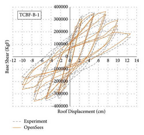
To evaluate the accuracy of the modeling process of the steel-HSS braced frame, a two-story braced frame, where specimen and testing configurations are shown in Figure 9, tested by Lai et al. [11], is investigated under cyclic analysis in two dimensions using OpenSees finite element software; specimens specifications are listed in Table 4. Comparison of experimental and numerical results by OpenSees is shown in Figure 10. It is observed that the numerical results are in agreement with the experimental results.
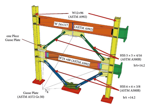
| Name | Column and beam | Brace | Test method |
|---|---|---|---|
| TCBF-B-1 | W12 × 96 (columns and beams (ASTM A992)) | HSS 5 × 5 × 5/16 HSS 6 × 6 × 3/8 | Cyclic loading |
3.2. Timber-Steel-BRB Frame Verification
The frame under study in Figure 11 is to perform verification of TS-BRB cyclic algorithms which is related to the article of Eric Ko et al. [6], which is a single-story steel frame equipped with TS-BRB glulam casing. The following figures show the details and dimensions of the relevant model.
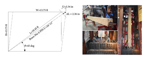
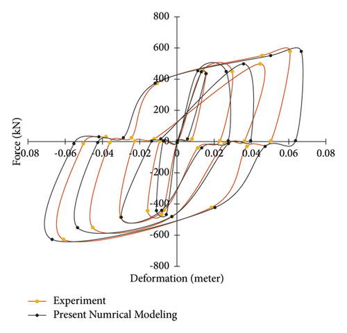
Cyclic analysis was performed in two dimensions using OpenSees finite element software. The width and the height of the frame were assumed to be 4.19 m. The floor mass was allocated as a nodal mass at the intersection of beams and columns. This mass was assigned only for the X degree of freedom to activate the higher modes of the structure, and negligible masses of 1e-9 were also assigned to the second and third degrees of freedom. Frame connections to the foundation were considered rigid. The yield strength and modulus of elasticity of the steel used for the beams and columns were 275 MPa and 200 GPa, respectively, and their behavior was introduced as uniaxial material using the steel02 command in OpenSees. All local coordinate conversions (hardness transfer and element strength) were performed in Appendix software using the P-Delta option in the geometric transfer command. This command is used to construct a linear coordinate conversion that transfers the stiffness and strength of the elements from a local system to a global coordinate system by performing a linear geometric transformation considering the effects of the second P-Delta. The beam is W-shaped in dimensions of 0.2 × 0.1 m. The dimensions of the box columns were 0.457 × 0.457 × 0.012 m. For modeling beams and columns, a nonlinear column beam element with distributed plasticity with five integration points along the element was used. The yield strength and modulus of elasticity of the steel used for the steel core of the TS-BRB brace are 248 MPa and 200 GPa, respectively, and their behavior was introduced as uniaxial material using the steel02 command in OpenSees. This is a rectangular steel core with an area of 1548 mm2. In OpenSees software, for modeling the TS-BRB brace CorotTruss command was used. Figure 12 shows the validation result of the cyclic solution algorithm performed in OpenSees finite element software. The vertical and horizontal axes are the axial resistive force of the brace (KN) and the deformation of the brace joint with the gusset plate in the direction of the length of the brace, respectively. As can be seen, the curves have a good and acceptable fit.
3.3. Glulam Braced Frame Verification
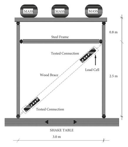
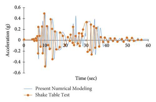
To perform verification of glulam braced frame, the tested frame in Figure 13 was selected; the tested frame contains two planar four-hinged steel frames located parallel to each other 1.2 m apart. The two planar frames were attached with cross beams as well as with diagonal steel cross braces to supply the out-of-plane stiffness. The four-hinged steel frame was designed to supply vertical support for an inertial mass consisting of three concrete blocks attached to the top of the frame. The three concrete blocks had a total mass of 4500 kg (10000 lb). The frame itself has no lateral resistance, so the inertial forces are transmitted directly to the component tested, which in this case was the diagonal timber brace with connections on both ends. A photograph of the frame with the timber brace member inserted and ready for testing is shown. One of the crossbeams of the frame near the top was designed to assist the diagonal brace element intended for testing. The brace was held at the bottom by a specially designed fixture that was attached to the specimen attachment beam. Load cell was attached at the top end of the brace to directly compute the axial load induced in the member. Rotational pins were used on both ends of the brace to prevent the progress of bending moments on the brace. Because of the weight of the setup at the top of the diagonal brace (fixture plus a load cell), rollers were attached to avoid out-of-line displacements of the brace that would cause rotation in the connection. The diagonal braces used in the tests consisted of spruce-pine (SP) Glued Laminated Timber (130 × 152 mm) in cross section. Brace specimens were approximately 3.1 m long and had the same connection on both ends. The average modulus of elasticity of glulam is 10844 MPa (1572.8 × 103 psi), time history analysis was performed using OpenSees finite element software under Joshua earthquake, and acceleration histories of the top frame were found and there was an acceptable fit to the shake table acceleration history (see Figure 14).
4. Seismic Analyses Strategies
Seismic performance of structural elements under seismic loading requires extensive research. Several research bodies all over the world have been interested in investigating the seismic response of various types of structural systems. In general, research on the seismic performance of structural systems can be categorized into two groups: analytical investigation and experimental research. Because of innovation in the fields of electronics and mechanics, the progress of those two groups of research has been important. At present, simulating the static and dynamic earthquake responses of complex structural systems is not very difficult. Seismic analysis is a tool for estimating the response of structures in the process of designing earthquake-resistant structures or vulnerable structures. In principle, the problem is difficult because the structural response to severe earthquakes is dynamic, nonlinear, and random.
4.1. Pushover Curves of Selected Portal Frames
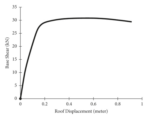
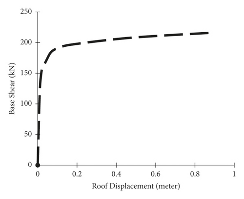
In the above equation, Fx is the applied lateral force at level “x,” W is the story weight, h is the story height, and V is the design base shear. K is set equal to unity in an inverted triangular distribution of the lateral load. In this study, the portal steel frame is analyzed under pushover loading in four conditions: without bracing, steel-HSS braced, timber based glulam braced, and timber-steel buckling restrained braced (TS-BRB); their pushover capacity curves are shown.
According to the results of pushover analysis, as shown in Figures 15–18, the portal steel frame without bracing has the lowest shear capacity. The slope of the elastic part of the capacity curve in the frame braced with the glulam brace is less than the slope of the frame braced with steel-HSS and TS-BRB braces; this means that the elastic stiffness of the frame braced with a glulam brace is less than the elastic stiffness of the frame braced with the steel-HSS and TS-BRB. The portal steel frame without bracing has the lowest values of elastic stiffness and seismic capacity, and even the slope of the part after the submission of the pushover curve is less than the frames braced with steel-HSS, timber based glulam, and TS-BRB. Comparative results of capacity curves of steel-HSS braced frames and frame braced with timber-steel buckling restrained brace (TS-BRB) show that the elastic stiffnesses (slope of the elastic region of the capacity curve) of the two types of braces are almost the same, but the shear values and the total capacity of the TS-BRB braced frame are more compared to the frame braced with the steel-HSS. This indicates that, in the details and dimensions of the same design sections (equal hardness), the frame braced with TS-BRB has better performance and more capacity than the frame braced with the steel-HSS. Comparisons of base shear equivalent to the first plastic hinge formation and displacement values of frames are listed in Table 5.
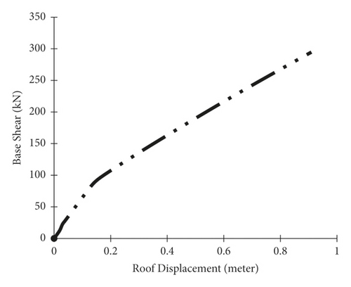
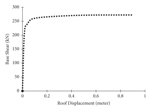
| Type of portal steel frame | First plastic hinge base shear (KN) | First plastic hinge point (m) | Brace effective area dimensions (mm) | Unit weight of brace length (Kg/m) |
|---|---|---|---|---|
| Steel-HSS Braced | 171 | 0.019 | HSS (60 × 60 × 3) | 5.18 |
| TS-BRB | 222 | 0.019 | (50 × 20) | 7.85 |
| Glulam braced | 63 | 0.082 | (100 × 100) | 4.5 |
| Unbraced portal | 28 | 0.174 |
4.2. Strength and Stiffness Degradation Investigation of Selected Portal Frames
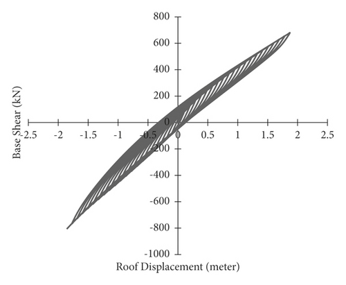
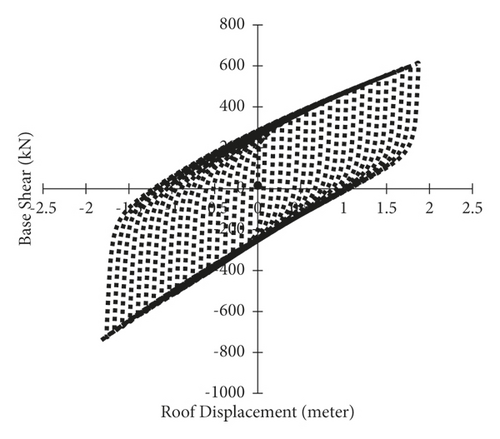
In cyclic analysis, cyclic loading is applied to the structure and the effects of capacity reduction during cyclic loading can be observed. The result of cyclic loading is usually the curves of the force against the displacement from which the seismic performance of the studied members can be better achieved [15]; the greater the area below these curves, the more energy dissipation. On the other hand, resistance drop should not occur in high cycles. To apply cyclic loading, standard protocols such as ATC-24 standard [16] and SAC standard protocol [17] should be used. In this study, the portal steel frame is analyzed under cyclic loading with a displacement loop of 4 m in four conditions: without bracing, braced with steel-HSS, braced with timber based glulam, and braced with timber-steel buckling restrained brace (TS-BRB); its hysteresis curves are obtained as follows.
According to the results of cyclic analysis, as shown in Figures 19–22, the unbraced portal frame has the lowest energy dissipation area and has strength and stiffness degradation. The area under the cyclic curve of the frame indicates the energy dissipation; in the case of using the steel-HSS brace, the number of cycles is much higher and there is no drop in strength and stiffness in the higher cycles. As a result, in a portal steel frame, the use of a steel-HSS brace is preferable. According to the results in Figure 22, the frame braced with timber-steel buckling restrained bracing (TS-BRB) is slightly harder than the frame braced with the steel-HSS brace, and the number of reciprocating cycles in both frames is almost the same, but the area under the cyclic curve of the frame braced with TS-BRB is more than that of the frame braced with the steel-HSS brace; the TS-BRB braced frame can resist base shear in tension; the reason for these advantages is that the TS-BRB brace does not buckle under compression, and, as a result, the axial tensile and compressive capacities are almost equal. Therefore, according to the results, the best performance is related to frame braced with timber-steel buckling restrained brace (TS-BRB). Using timber based glulam, steel-HSS, and TS-BRB braces can remove strength and stiffness degradation as shown in Table 6.
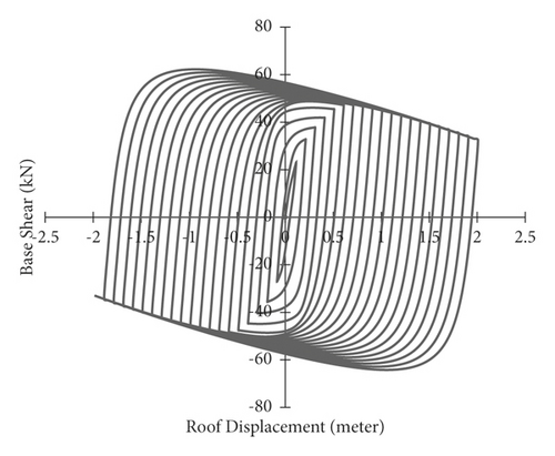
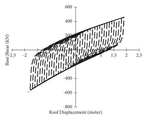
| Type of portal steel frame | Brace effective area dimensions (mm) | Strength degradation | Stiffness degradation |
|---|---|---|---|
| Steel-HSS braced | HSS (60 × 60 × 3) | No | No |
| TS-BRB | (50 × 20) | No | No |
| Glulam braced | (100 × 100) | No | No |
| Unbraced frame | Yes | Yes |
4.3. Drift Investigation of Selected Portal Frames
Incremental dynamic analysis is one of the new methods in performance-based earthquake engineering, which expresses the behavior of the structure in a wide range of different earthquake intensities. Also, due to the dynamic nature of this method, we can certainly see more realistic results compared to nonlinear static methods. The method is based on the fact that to control the structure is analyzed for several or a single record of earthquake acceleration to obtain several points. By drawing and connecting these points, a continuous picture of the spectrum of the behavior of the structure in all elastic stages to yield and finally the collapse of the structure is obtained and finally show a good view of the newest methods in performance [18]. This method has been adopted by the US Federal Emergency Management Agency (FEMA) and has been considered in the FEMA-350, FEMA-351, and HAZUS-MH MR-5 guides to determine the overall failure capacity of the structure; IDA involves performing multiple nonlinear dynamic analyses of a structural model under a suite of ground motion records [18]. Some fundamental parameters of the IDA analysis used in this paper are defined as follows.
4.3.1. Selected Scale Factor (SF)
The scale factor constitutes one-to-one mapping from the original to all its scaled pictures. Value of λ = 1 signifies the natural accelerogram, and λ < 1 is a scaled-down accelerogram, while λ > 1 corresponds to a scaled-up one. Scale factor is the easy way to determine the scaled images of an accelerogram.
4.3.2. Selected Intensity Measure (IM)
4.3.3. Selected Damage Measure (DM)
Damage measure is positive scalar DM ∈ [0; +∞] that determines the additional response of the structural model due to a prescribed earthquake loading. In other words, a damage measure is an observable quantity that is part of, or can be deduced from, the output of the corresponding nonlinear dynamic analysis. In this paper, the maximum interstory drift is selected seismic damage measure [19].
4.3.4. Summarized IDA or Fractile Curves
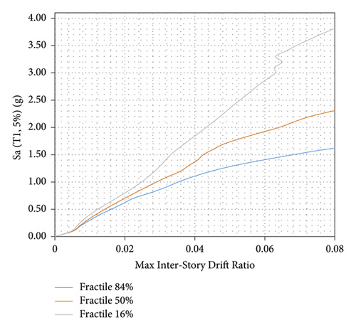
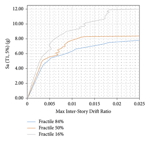
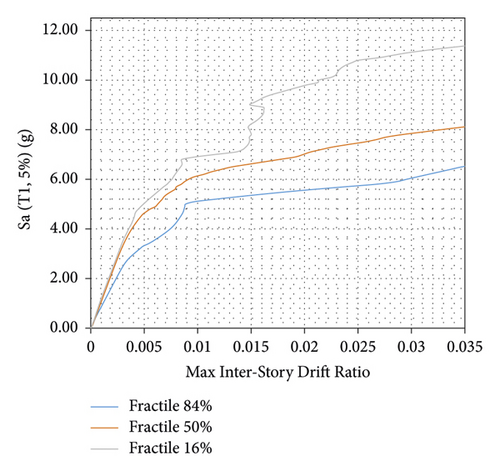
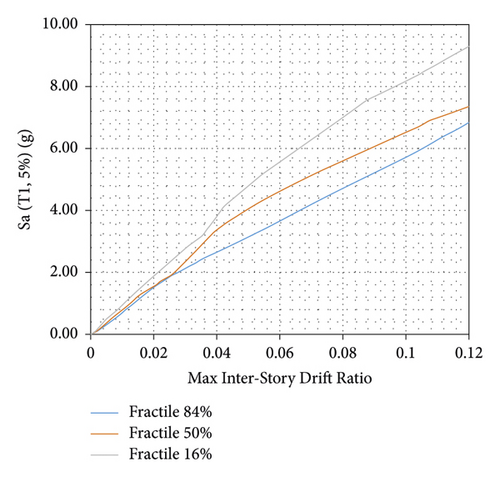
After performing IDA analysis under several different earthquake records, a set of IDA curves are obtained. Given a large number of curves, each of which shows the specific behavior of the structure under the earthquake records and does not indicate the overall performance of the structure in the case of earthquake types; to achieve a general state of structural behavior and reduce information scatter, the category of IDA curves can be summarized [20]. This is possible through statistical methods and, in this method, the performance of the studied structures can be evaluated more tangibly. Therefore, three statistical values of 16%, 50%, and 84% are extracted from each of the categories of IDA curves and they are used to compare different categories of curves with each other and evaluate the probabilities of structures. In this paper, the portal steel frame is IDA analyzed in four conditions: without bracing, braced with steel-HSS, braced with timber based glulam, and braced with timber-steel buckling restrained brace (TS-BRB). Summarized IDA or fractile curves are shown in Figures 23-30.
4.4. Selected Performance Level
In this study, the immediate occupancy (IO) capacity of the frames is compared under selected earthquake records. Immediate occupancy performance level corresponds to a small reduction in lateral stiffness and strength or the structure substantially retains original strength and stiffness, minor cracking of facades, partitions, ceilings, and structural elements can be restarted.
4.5. Limit States on IDA Curves
For performance calculations, limit states on the IDA will be defined as listed in Table 7. Three commonly used limit states are considered, namely, immediate occupancy, collapse prevention (as per FEMA [21]), and global dynamic instability. For the models in this paper, immediate occupancy is defined according to FEMA guidelines [21]. The immediate occupancy limit state is defined at θmax = 1% for ordinary moment frame and θmax = 2% for special moment frame.
| Building height | Performance level | |
|---|---|---|
| Immediate occupancy | Collapse prevention | |
| Interstory drift angle capacity C | Interstory drift angle capacity C | |
| Low rise (3 stories or less) | 0.02 | 0.1 |
| Mid rise (4–12 stories) | 0.02 | 0.1 |
| High rise (>12 stories) | 0.02 | 0.08 |
4.6. Research on Near-Fault Earthquakes
In areas near the fault, ground movements are influenced by the fracture mechanism, the direction of fault expansion is related to the site, and the permanent displacement of the ground is due to the static slide of the fault. However, a single distance is not defined as a close range of the fault, and there is a difference of opinion among researchers in this regard. For this reason, researchers have suggested different distances between 10 and 60 km as the boundaries of the near field. UBC-97 regulations provide a distance of fewer than 15 km from the center as the near area. But today it is commonly assumed that recorded movements less than 20 km from the fault location and the epicenter of the earthquake are near-fault maps. The characteristics of near-fault movements are directly related to the seismic source mechanism, the direction of fault rupture relative to the site, and the permanent changes in the ground at the site due to tectonic movements. These properties include the effect of rupture orientation, permanent deformation of the Earth, and high-frequency content. Somerville et al. [22] showed that the effects of orientation increase the response spectrum in periods longer than 0.6 seconds. To compare the response spectrum of near and far earthquakes, 15 ordinary earthquake maps were selected. Chopra et al. [23] found that near-fault effects have significant influence on the quadratic response spectrum in a way that reduces the areas sensitive to velocity and increases the areas that are sensitive to displacement and acceleration.
4.6.1. Earthquakes Records for IDA and Time History Analysis
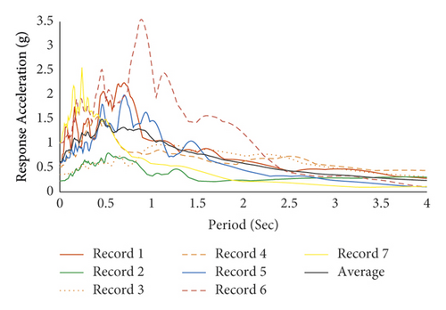
To more accurately evaluate the models in this study, it is necessary to simulate the time history analysis of the models using several ground acceleration records. For this purpose, seven seismic records to type C soil have been obtained from Pacific Earthquake Engineering Research Center. All records are from earthquakes with a magnitude of higher than 6.5 on the Richter scale. Table 8 shows the near-fault histories of type C soil, including peak ground acceleration (PGA) and earthquake magnitude. The selection of stories plays a very significant role in the results of time history analysis, and in the selection of records, in this paper, we used the results of studies conducted by Erol Kalkan et al. [24] in which Fling-Step and Forward-Rupture Directivity occurred. Acceleration response spectrum of selected records and their average are shown in Figure 31.
| No. | T (sec) | Dt (sec) | Earthquake name | Year | Station | Magnitude (Richter) | PGA (g) |
|---|---|---|---|---|---|---|---|
| 1 | 90 | 0.005 | Chi-Chi-Taiwan | 1999 | TCU052 | 7.62 | 0.36 |
| 2 | 90 | 0.005 | Chi-Chi-Taiwan | 1999 | TCU068 | 7.62 | 0.512 |
| 3 | 90 | 0.005 | Chi-Chi-Taiwan | 1999 | TCU074 | 7.62 | 0.596 |
| 4 | 90 | 0.005 | Chi-Chi-Taiwan | 1999 | TCU084 | 7.62 | 1.0 |
| 5 | 90 | 0.005 | Chi-Chi-Taiwan | 1999 | TCU129 | 7.62 | 1.0 |
| 6 | 35 | 0.005 | Kocaeli | 1999 | Yarimca (YPT) | 7.51 | 0.23 |
| 7 | 25 | 0.005 | Loma Prieta x | 1989 | LGPC | 6.93 | 0.57 |
According to the results of the IDA curves, as shown in Figures 23–26, the portal steel frame without bracing has the maximum interstory drift. In steel-HSS and timber-steel-BRB braced frames, the maximum interstory drift is obtained for the values of constant seismic intensity. Also, in the case of using the steel-HSS brace, timber based glulam brace, and timber-steel-BRB, the maximum values of interstory drift occur at higher seismic intensities compared to the portal steel frame without bracing. Therefore, the use of steel-HSS brace, timber based glulam brace, and timber-steel-BRB has a significant impact on the reduction of the dynamic response of portal steel frame. The results show that the frame braced with the steel-HSS brace and the frame braced with timber based glulam brace have better seismic performance in reducing the maximum amount of interstory drift, increasing energy dissipation, and reducing the dynamic response. In general, it can be stated that, in all seismic intensities, in the cases of using timber based glulam, steel-HSS and timber-steel-BRB braces compared with portal steel frame without bracing, the demand values are reduced several times; this indicates the extra stiffness that the braces, steel-HSS, timber-steel-BRB, and timber based glulam, impose on the portal steel frame. The greatest reduction in seismic demand of interstory drift is in frame braced with timber-steel-BRB, and, as a result, timber-steel-BRB has the best energy dissipation and seismic performance. The occurrence of this optimal seismic performance can be due to symmetrical and stable hysteresis curves of buckling restrained braces that can experience the same capacities in tension and compression. Compared capacity and maximum interstory drift ratios (θmax) of braced frames for immediate occupancy are listed in Tables 9–12.
| Fractile (%) | Type of frame | Sa (T1, 5%) (g) | θmax |
|---|---|---|---|
| 16 | Unbraced portal | 0.8 | 0.02 |
| 50 | Unbraced portal | 0.7 | 0.02 |
| 84 | Unbraced portal | 0.6 | 0.02 |
| Fractile (%) | Type of frame | Sa (T1, 5%) (g) | θmax |
|---|---|---|---|
| 16 | Steel-HSS braced portal | 9.7 | 0.02 |
| 50 | Steel-HSS braced portal | 7 | 0.02 |
| 84 | Steel-HSS braced portal | 5.6 | 0.02 |
| Fractile (%) | Type of frame | Sa (T1, 5%) (g) | θmax |
|---|---|---|---|
| 16 | Glulam braced portal | 1.8 | 0.02 |
| 50 | Glulam braced portal | 1.7 | 0.02 |
| 84 | Glulam braced portal | 1.6 | 0.02 |
| Fractile (%) | Type of frame | Sa (T1, 5%) (g) | θMax |
|---|---|---|---|
| 16 | Timber-steel-BRB portal | 11.6 | 0.02 |
| 50 | Timber-steel-BRB portal | 8.6 | 0.02 |
| 84 | Timber-steel-BRB portal | 7.6 | 0.02 |
4.7. Displacement History Investigation of Selected Portal Frames
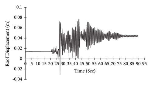
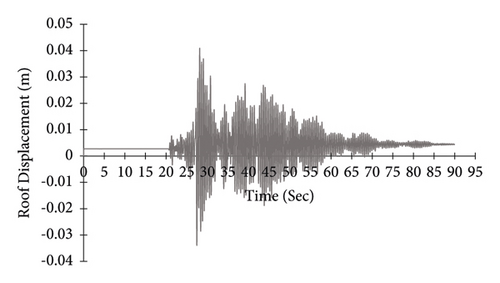
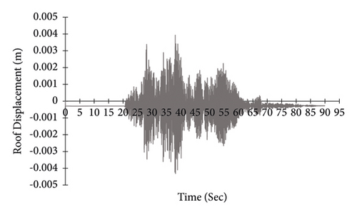
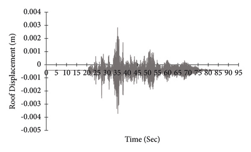
In the above formula, m and k are the mass and stiffness matrices, respectively, and α and β are proportionality factors that are calibrated to result in a predefined percentage of critical damping (ξ) at two vibration periods. In time history analysis, the response of the building under the stimulation of actual earthquake histories is determined using dynamic relationships in short time. In this method, the response of the structure is based on at least three records. If less than seven records are selected for analysis, their maximum effect should be considered to control deformations and internal forces. If seven records or more are used, the average value of their effect can be considered to control deformations and internal forces [26]. Displacement history of portal frame is obtained in four conditions: without bracing, braced with steel-HSS, braced with timber based glulam, and braced with timber-steel buckling restrained brace (TS-BRB). Figures 27–30 are curves for roof node displacement histories of the portal steel frame without bracing, braced with steel-HSS, timber based glulam, and timber-steel buckling restrained brace (TS-BRB), respectively. The data from the time history analysis is under record number five, as shown in Table 8.
According to the results of time history analysis, as shown in Figures 27–30, the use of steel-HSS, timber based glulam, and timber-steel-BRB braces in the portal steel frame affects the history of displacement of the frame roof node. Therefore, the use of the steel-HSS brace, timber based glulam brace, and timber-steel-BRB brace has a significant effect on increasing energy dissipation, reducing the dynamic response of structures, and reducing the amount of residual displacement after the earthquake as summarized in Table 13.
| Type of portal steel frames | Brace effective area dimensions (mm) | Unit weight of brace length (kg/m) | Maximum roof displacement (m) |
|---|---|---|---|
| Steel-HSS braced | HSS (60 × 60 × 3) | 5.18 | 0.0038 |
| TS-BRB | (50 × 20) | 7.85 | 0.0027 |
| Glulam braced | (100 × 100) | 4.5 | 0.04 |
| Unbraced portal | 0.08 |
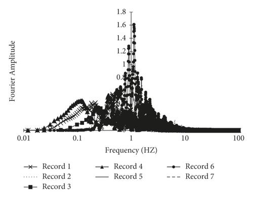
The linear and nonlinear response of structures is greatly affected by the frequency content and basically in each earthquake record one or two components decomposed from the record with a short frequency range (with a period close to the natural period of the structure) affecting the response of structures. This is why classifying records based on frequency content can be very useful for selecting the right accelerometer for time history analysis. In addition to the concentration of energy in frequency, the concentration of energy in time is also very important in the response of structures. The three main characteristics of an earthquake are amplitude, duration, and frequency content. There are different parameters to determine these three characteristics, some of which describe only one of the above three characteristics, while others describe two or even three characteristics. Parameters used to describe the amplitude of an earthquake include the peak ground acceleration (PGA), peak ground velocity (PGV), and peak ground displacement (PGD). Different methods are used to determine the duration of an earthquake, the most important of which is to determine the duration based on the ground acceleration, the intensity of the arias, and the acceleration of RMS. The dynamic response of structures is very sensitive to the loading frequency. Earthquakes create very complex loading in a frequency range. Therefore, the study of frequency content is very important. In general, how the amplitude of the ground is distributed at different frequencies is called frequency content. The frequency information of earthquakes, unlike the amplitude and duration of the earthquake, cannot be extracted directly from the time history of the earthquake record, but this information is hidden, which requires various mathematical tools to extract it. The Fourier spectrum and the power spectrum are traditionally used to determine the frequency content of earthquakes. Fourier transform is a bridge between time and frequency which transmits the signal from the time domain to the frequency domain and extracts the signal information in the frequency domain. This type of conversion fails to determine the exact time of the different frequencies and can only determine the existence of the frequency. This type of frequency content expression is very useful for static signals. If the static signal has a frequency, that frequency is present in the whole time range. On the other hand, the time signals in earthquake engineering are inherently nonexistent in both frequency content and amplitude changes. In this study, to better extract the frequency information of the signals of seven selected records, their Fourier spectra are plotted in Figure 32.
5. Conclusions
- (i)
According to the results of pushover analysis shown in Table 5, the frame without bracing has the lowest seismic capacity and the lowest amount of yield base shear. By adding timber based glulam, steel-HSS, and timber-steel-BRB braces, there is a considerable increase in base shear capacity equivalent to the first plastic hinge, 2.25, 6, and 7.93 times, respectively; this indicates the extra shear capacity that the braces give to the unbraced portal steel frame.
- (ii)
Capacity curves of the frame braced with the steel-HSS brace and the frame braced with timber-steel-BRB brace show that the elastic stiffnesses (slope of the elastic region of the capacity curve) of the two types of braces are almost the same, but the equivalent yield base shear values and capacity of the frame braced with timber-steel-BRB are about 22.9% more compared to the frame braced with the steel-HSS brace. The frame braced with timber-steel-BRB has more stiffness than the frame braced with the steel-HSS so the frame braced with timber-steel-BRB can resist base shear more and has the best performance.
- (iii)
Compared to cyclic curves in Figures 19–22, it is concluded that the portal steel frame without bracing has the lowest surface area below the cyclic curve; it means that it has the lowest earthquake damping, resistance drop occurred in upper cycles, and also there are strength deteroiation and stiffness degradation. By adding timber base and steel braces, there is a considerable increase in energy dissipation and resistance drop did not occur in high cycles; also there is no strength and stiffness degradation. This indicates the extra stiffness and energy dissipation capacity that the braces, steel, glulam, and timber-steel-BRB, give to the unbraced portal steel frame.
- (iv)
Due to the elastic properties of the wood, the hysteresis curve of the glulam braced frame is thin.
- (v)
Compared to summarized IDA or fractile curves of 16%, 50%, and 84% from Tables 9–12 in general, it can be stated that, in all seismic intensities, in the cases of using timber based glulam, steel-HSS, and timber-steel-BRB braces in portal steel frame, the demand values are reduced several times; this indicates the extra lateral strength that the braces, steel-HSS, timber based glulam, and timber-steel-BRB, give to the portal steel frame.
- (vi)
Comparison of 16% summarized IDA curves shows that the interstory drift of 0.02 in the unbraced portal frame is obtained in spectral acceleration corresponding to the first model of the structure with 5% damping of 0.8 g, but with the addition of wooden glulam brace this interstory drift is obtained in 1.8 g; this indicates 1 g extra intensity measure capacity. Using glulam brace has a significant role in the control of interstory drift compared to its weight.
- (vii)
Compared to displacement histories obtained from time history analysis, using steel-HSS, timber based glulam, and timber-steel-BRB braces in the portal steel frame, the decrease in maximum roof displacement is 95%, 50%, and 96.6%, respectively, This indicates a significant effect of braces on the displacement control of the roof node as summarized in Table 14.
- (viii)
In timber-hybrid structures steel is strong with significant postyield deflection capability, known as ductility; timber is comparatively weaker, usually requiring larger sections, resulting in stiffer systems; wood does not produce postyield deflection, especially when loaded perpendicular to the grain.
- (ix)
Hybrid timber-steel-BRB frames counteract the negative postyield stiffness that occurs due to P-Delta effects. They are more effective on buildings where P-Delta effects are more critical.
- (x)
The repair costs of the structures with hybrid timber-steel-BRB frames will be less due to lower residual drifts.
- (xi)
Due to low density of wood by using timber based braces, there is a considerable reduction in the frame weight corresponding to its strength.
- (xii)
The results of the analysis showed that glulam can withstand different dynamic loads as a brace and confinement of the buckling restrained brace in hybrid timber-steel structures, in which case there is a significant reduction in the weight and cost of estimation of the structure.
| Type of portal steel frame | Brace effective area dimensions (mm) | Maximum roof displacement (m) | Decrease in maximum roof displacement (%) |
|---|---|---|---|
| Steel-HSS braced | HSS (60 × 60 × 3) | 0.0038 | 95.2 |
| TS-BRB | (50 × 20) | 0.0027 | 96.6 |
| Glulam braced | (100 × 100) | 0.04 | 50 |
| Unbraced | 0.08 | — |
Conflicts of Interest
The authors declare that they have no conflicts of interest regarding the publication of this paper.
Acknowledgments
The authors thank Professors of the Civil Engineering Department, K. N. Toosi University of Technology, for their complete guidance in this research and also thank the laboratory officials of this university for their cooperation in getting experimental data for numerical modeling.
Open Research
Data Availability
The data used to support the findings of this study are available from the corresponding author upon request.


