Experimental Study on the Reliability of an Active Unloading System for Strengthening of Reinforced Concrete Columns
Abstract
In strengthening and retrofitting of reinforced concrete (RC) frame structures, especially in the case of column replacement, unloading of existing columns usually plays an important part in the construction. However, the reliability of the commonly used active unloading system for RC columns can only be evaluated by real-time monitoring of the unloading status during the construction process, which will threaten the safety of the personnel and structures, especially in the case of unloading with large amplitude. In addition, the commonly adopted passive unloading methods are unable to actively control the unloading force. Therefore, an unloading scheme with active control of the unloading process was proposed, and its reliability was experimentally investigated in the present study. According to the requirements of the unloading force, an active unloading self-balancing system using the steel diagonal braces and prestressed steel tie rods was designed for the RC column structure. The vertical load was applied by a hydraulic jack mounted on top of the RC column, and the real-time monitoring data analysis was adopted to verify the feasibility of the active unloading plan and the reliability of the force transmission. The test results indicated that the proposed active unloading control technology is reliable in force transmission.
1. Introduction
The concrete strength sometimes fails to reach the expected value in constructions due to the factors such as the material, mix ratio, and maintenance. In that case, the strengthening and retrofitting of the concrete structures are often required. The concrete column replacement method is widely used because it can restore the original appearance after construction and does not change the use space. In replacing the concrete columns, the unloading of the column is a frequently used construction method. The axial pressure of the frame column was gradually reduced by being supported and unloaded, which can avoid the danger compared with the direct replacement of the with-load concrete column. Therefore, frame column unloading is the key in the process of column replacement.
By adding a posterior web column to an existing RC frame beam, Li et al. [1] proposed a method to regulate the bending moment distribution of the frame beam and reduce the peak bending moment without reducing the headroom. Li et al. [2] used a temporary underpinning system with a bollard beam and wall column to correct the uplifting deviation and conducted a numerical simulation to study the failure mechanism of the column replacement. Du et al. [3] conducted a series of experiments on 16 groups of frame column-double-beam underpinning joints and clarified the force mechanism and failure mode. Ling et al. [4] proposed an underpinning structure system using the inclined columns and the second and third underground floors to allow the subway tunnels to pass through underground buildings and achieved good results.
Jing et al. [5] adopted the postanchorage technology on brick walls, where the steel plates and the brick walls were connected as a whole to ensure that the two could be deformed together so that the original load on the wall was transformed into a steel plate-brick masonry composite beam and column frame. The feasibility of the underpinning technology was verified through practical engineering applications. Yue et al. [6] carried out an experimental verification on the performance of using high-strength bolts to impose prestress on the interface between the new and old concrete of the beam and column to improve the bearing capacity of the underpinning joints. Lopes et al. [7] used six hydraulic jacks arranged on the micropiles around an underpinned column to carry the load and reduce the vertical deformation of the upper structure. Rutz et al. [8] introduced the design and construction of underpinning a building foundation with deep rock cast-in-place piles as a support, which achieved good results.
Based on the actual on-site construction conditions and taking the shield construction of the lower part of a dormitory in a coal factory as the research object, Su [9] optimized the active underpinning technology by designing an active underpinning system with “one beam supporting multiple columns.” The research results showed that the use of active underpinning optimization technology can improve stability in construction. Yue et al. [10] used two concrete underpinning beams and two connecting beams as an underpinning structure and experimentally and numerically studied the failure modes of the concrete underpinning beams and columns.
According to previous studies, the replacement of concrete frame columns mainly adopts a passive unloading scheme, in which the unloading value cannot be controlled. When the passive unloading scheme is applied in the practical application, the safety of the construction process can only be detected by real-time monitoring of the unloading condition, which will dramatically threaten the safety of the personnel and structures, especially in the case of unloading with a large amplitude. Therefore, to ensure safety and reliability during the construction of column replacement, it is necessary to control the unloading process by active unloading technology.
To overcome the shortcoming of the existing unloading technology at the stage of RC column strengthening or replacement, this paper proposed an active unloading system with steel inclined braces and prestressed steel tie rods to actively control the unloading process. An experimental program was conducted to verify the reliability of the active unloading scheme was reported. In this program, two key points are concerned: (1) the difference between the theoretical and measured stress and deflection of the main components; (2) the damage of the concrete and the straightness of the steel bolts after applying axial compression to the top of the frame column. Based on the analysis of the test results, an active unloading scheme that can be used in the stage of column replacement was proposed, and the reliability of the unloading system was evaluated, which provided the technical support and scientific basis for the active unloading technology of frame columns.
2. Design and Assembly of the Test Specimen
2.1. Mechanical Analysis
In the proposed active unloading control system, the axial forces in the two steel diagonal braces were generated by the tension of the steel tie rods using a hydraulic jack, which caused an upward supporting force to reduce the axial force, that is, unloading of the target frame column to allow column strengthening or replacement.
In this section, the following three aspects were investigated: (1) the theory of the joint force of multiple steel bolts and determine the reliability of the connection using the multiple steel bolts and the gusset plates; (2) the stability and reliability of the entire unloading system; and (3) the relationship between the tension of prestressed steel tie rods and the value of the unloading force and provide a basis for controlling the value of the unloading force through prestressed steel tie rods in actual engineering construction.
The test structure was mainly composed of RC columns, steel diagonal braces, and prestressed steel tie rods. Double-piece steel and self-balancing tie rods were used to form a self-balancing frame, and the test components were vertically arranged on the ground. To clarify the load transfer path, short columns were adopted for the frame columns, and the restraint was released from the lower part of the system. The pressure was applied to the frame column through the jack. The frame columns transmitted the pressure to the steel diagonal braces through the steel bolts and the gusset plates. The steel diagonal braces transmitted the vertical axial force to the lower load-bearing steel beam and formed a vertical balance with the upper load-bearing steel beam through the self-balancing rods. The horizontal force generated by the steel diagonal braces was counteracted by the prestressed steel tie rods to form an in-plane horizontal balance. Figure 1 is a schematic diagram of the test components. The red arrows indicate the active tension force, and the blue arrows indicate the load transfer mode. Figure 2 is a three-dimensional view of the test structure. Descriptions of the main components in Figure 1 are as follows: 1 – temporary shelving pier, 2 – underbearing steel beam, 3 – steel diagonal brace base, 4 – temporary support frame, 5 – prestressed steel tie rod, 6 – steel diagonal brace, 7 – the upper node of the steel diagonal brace with the concrete frame column, 8 – steel bolt, 9 – RC frame segment, 10 – self-balancing tie rod, 11 – upper-bearing steel beam, and 12 – hydraulic jack.
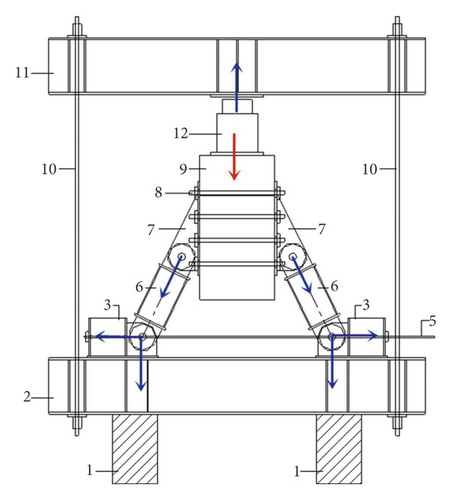
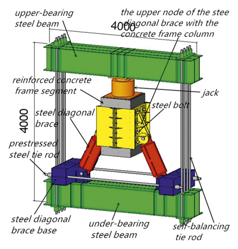
In this test, a hydraulic jack was used to apply pressure on the column. To avoid concentrated pressure on the column section, a steel plate was placed between the hydraulic jack and the top surface of the concrete frame column. The load-bearing steel beam was directly placed on the jack, and the jack was directly placed on the steel plate placed on the top surface of the concrete frame column. Therefore, there was only pressure transferred among the upper load-bearing steel beam, the hydraulic jack, the steel plate, and the frame column. The frame column and the gusset plate were connected by steel bolts. Steel diagonal braces and the gusset plate were fixed by steel pin shafts. The steel diagonal brace supports were also fixed with steel pin shafts, forming an in-plane rotatable hinge. The upper load-bearing steel beam and the lower load-bearing steel beam formed a balanced system through the tensioned tie rods. The entire test component was placed on two temporary shelving piers on the ground to form a test system.
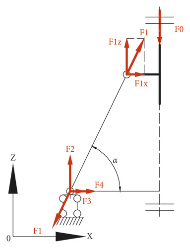
The test specimen could be simplified into the calculation model in Figure 3. Because the weight of each component was rather small compared with the force imposed by the hydraulic jack, its influence was ignored in the present study. The calculation of internal force of each component was determined according to structural mechanics. Once determined the axial force of the prestressed steel tie rods, the hydraulic jack loading value can be controlled by the angle between the steel diagonal braces and the prestressed steel tie rods and the tension force of the prestressed steel tie rods. Therefore, in actual engineering, the axial force of the prestressed steel tie rods and the inclined angle can be used to actively control the value of the unloading load.
- (1)
Check for the synergy effect of multiple steel bolts
-
Whether multiple steel bolts can work together during the test and how much reduction factor should be considered were the key in the strength checking of steel bolts. Considering that no relevant specification for the strength checking calculation of multiple steel bolts, this study referred to the calculation formula in the “Steel Structure Design Standard” (GB 50017–2017) [11] for the checking calculation. According to the specifications in the standard, when the connection length l1 of the steel pin along the direction of axial force is greater than 15d0 (d0 is the hole diameter), the design value of the steel pin bearing capacity should be multiplied by the reduction factor (1.1 − l1/150d0). When it is greater than 60 d0, the reduction factor is taken as a fixed value of 0.7.
-
Check for the shear strength of steel bolts:
(7) -
Check for the bearing strength of steel bolts:
(8) -
Check for the net section strength of the gusset plate:
(9) -
where τ is the shear stress of the steel bolt; σ is the compressive stress of the gusset plate; σc is the compressive stress of the steel bolt; , , and f are the designed value of the shear strength, compressive strength, and tensile strength of the steel bolt, respectively; n is the number of the steel bolts; η is the strength reduction coefficient of the steel bolts; d is the diameter of the steel bolts; t is the thickness of the gusset plates; b is the width of the gusset plate; m is the number of steel bolts with dangerous sections; and d0 is the diameter of the steel pinhole.
- (2)
Check for the strength of the steel diagonal brace
(10) -
Check for the stability of steel inclined braces:
(11) -
where σ is the stress of the steel diagonal brace, A is the section area of the steel diagonal brace, φ is the stability factor of the axial compression component, and f is the designed value of the tensile strength of the steel.
- (3)
Check for the strength of the prestressed steel tie rod
-
Checking formula of the tensile strength of prestressed steel tie rods:
(12) -
where σ is the stress of the prestressed steel tie rod, d is the diameter of the prestressed steel tie rod, n is the diameter of the prestressed steel tie rod, and f is the designed value of the tensile strength of the steel.
2.2. Design of Each Component
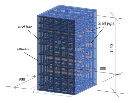
The test structure was designed with a scale ratio of 1:1 to the prototype structure, and the main components were designed according to the formulas in Section 2.1. The load applied in this test was 3,276 kN. Based on strength checking calculations, the upper and lower load-bearing steel beams were manufactured with two 600 mm × 300 mm double-piece steel plates, and the self-balancing tie rods were made of 8 fine-rolled rebars with a diameter of 40 mm to form a self-balancing frame. The concrete frame column was designed according to an actual project. The cross-sectional dimensions of the frame column were 800 mm × 900 mm, and the height was 1,450 mm. The C25 grade concrete HRB400 grade steel was adopted. The frame column was designed with 4 corner bars with a diameter of 25 mm and additional 4 bars with a diameter of 22 mm on each side. The 8 mm diameter stirrup with a pitch of 100 mm was configured within the range of 500 mm from the top surface of the column, and the 8 mm diameter stirrup with a pitch of 200 mm was configured in the remaining region. After the RC frame column was cured for 28 days, the holes with a diameter of 60 mm were drilled. A total of 4 rows of holes along the height direction with the center-to-center distance of 250 mm and 2 rows of holes along the width direction with the center-to-center distance of 400 mm were drilled. All the holes should not be inclined and run through in the width direction. The touch of the steel bars should also be avoided. To reduce concentrated pressure to crush the concrete, steel pipes with an outer diameter of 57 mm and an inner diameter of 48 mm were inserted into the core holes. The steel pipes were made of Q345 grade steel. The gap between the steel pipe and the concrete was filled with viscose glue, and the surface was polished before testing. Figure 4 represents a three-dimensional view of the RC frame column.
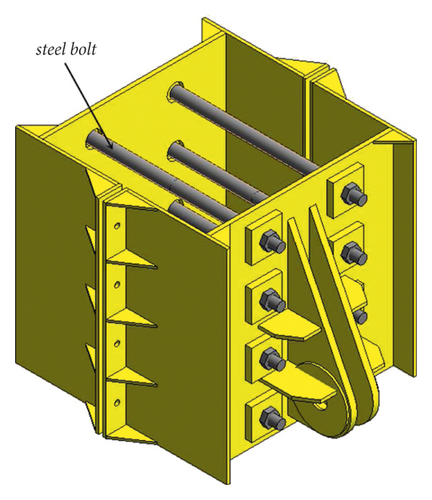
The steel diagonal braces and the frame column were connected with steel bolts and gusset plates, and the steel material was Q345B. Steel bolts with a diameter of 45 were inserted into the holes, and they were fixed in the two ends by screw nuts. Figure 5 shows a three-dimensional view of the gusset plates and the steel bolts.
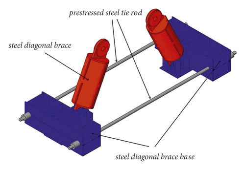
The steel diagonal braces used steel pipes with a diameter of 325 mm and a thickness of 16 mm. The spacing of the lug plates connected to the steel diagonal braces was 1,150 mm. The base of the steel diagonal braces was made of an I-beam with stiffening ribs. The I-beam and the lower load-bearing steel beam formed an angle of 64 degrees, and a 1 mm thick stainless steel plate was inserted between them to reduce the friction. The strength grades of the steel used for the diagonal braces and the base were both Q345B. Two prestressed steel tie rods with a diameter of 40 mm and a strength grade of PSB930 were pulled to impose the axial force in the diagonal braces. Figure 6 is a three-dimensional view of the steel diagonal braces and the prestressed steel tie rods.
2.3. Assembly of the Test Specimen
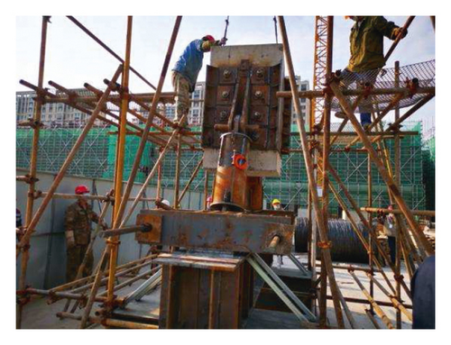
The assembly sequence of the test specimen is as follows: (1) install the temporary shelving piers according to the design position; (2) hoist the lower load-bearing steel beam and install it on the temporary piers; (3) set up the temporary support frame on the lower bearing steel beam, hoist the steel diagonal braces from the lower nodes to the top surface of the lower bearing steel beam, and install the prestressed steel tie rods between the lower nodes of the steel diagonal braces; (4) hoist the assembled RC frame column, steel bolts, steel diagonal braces, and upper nodes of the concrete frame columns to the temporary support frame as a whole; (5) hoist the steel diagonal braces to connect the upper nodes of the concrete frame column and lower nodes of the steel diagonal braces through the bolts and the steel diagonal braces; (6) install the loading hydraulic jack on the top of the RC frame column section; (7) hoist the upper load-bearing steel beam; and (8) install the self-balancing tie rods of the steel structure loading frame. Since the concrete frame column was not restrained in the horizontal direction in the test, it was necessary to ensure that the hydraulic jack, the concrete frame column, the steel diagonal braces, and the upper and lower bearing steel beams were strictly aligned during the test; otherwise, there would be horizontal instability. Figure 7 presents photos of the assembly process.

3. Instrumentation and Testing
3.1. Loading Procedures
In this test, a 100 MPa hydraulic jack was used to apply the vertical load with a total load of 3,276 kN and a load value of 40 MPa. In addition to the preloading stage, the standard loading process was divided into two stages. The preload was applied from 0 to 512 kN by 3 times to eliminate the gap between the test components and ensure that the components were in good contact. In addition, the reliability of the test equipment could also be checked in the preloading stage. The first standard load stage was divided into 14 levels from 0 kN to 3,276 kN, and the second stage was divided into 6 levels to 3,276 kN. The stresses of the main components were measured after each level of loading. Table 1 shows the test loading procedures.
| Load stage | Load case | Load amplitude (kN) |
|---|---|---|
| Preload stage | 1 | 187 |
| 2 | 349 | |
| 3 | 512 | |
| The first standard load stage | 1 | 187 |
| 2 | 349 | |
| 3 | 512 | |
| 4 | 837 | |
| 5 | 1,163 | |
| 6 | 1,488 | |
| 7 | 1,813 | |
| 8 | 2,138 | |
| 9 | 2,463 | |
| 10 | 2,626 | |
| 11 | 2,789 | |
| 12 | 2,951 | |
| 13 | 3,114 | |
| 14 | 3,276 | |
| The second standard load stage | 1 | 349 |
| 2 | 675 | |
| 3 | 837 | |
| 4 | 1,488 | |
| 5 | 2,138 | |
| 6 | 3,276 | |
3.2. Test Setup and Instrument
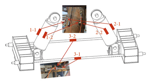
The axial force of the frame column was obtained by the hydraulic gauge of the jack, and the straightness of the steel bolts was visually observed after loading. The strains of the steel diagonal braces and the prestressed steel tie rods were measured by vibrating-wire-surface strain gauges, and the axial forces could then be calculated with the strains. The strain gauges were arranged in the middle section of the two steel diagonal braces and the prestressed steel tie rods. Figure 8 shows the diagram of the strain measurement points.
The testing of the specimen is as follows: (1) check the connection reliability of each node and the symmetry of the steel diagonal braces on the left and right sides of the RC frame nodes; (2) remove the temporary support frame at the lower part of the RC frame section to form an RC frame self-balancing force system of segment + steel diagonal braces + prestressed steel tie rods; (3) install strain gauges to achieve real-time monitoring of the force changes of steel diagonal braces and prestressed steel tie rods; and (4) apply the vertical load through the hydraulic jack.
During the loading process, real-time collection and analysis of the axial force data of the steel diagonal braces and steel tie rods were carried out. After the loading was completed, the components were disassembled to observe the damage of the concrete and the straightness of the steel bolts.
4. Test Results
4.1. Test Observation
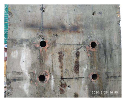
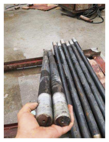
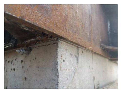
No obvious damage or deformation of each component occurred, and the test system was stable and reliable when it was loaded to the designed force value. After the loading was completed, the components were disassembled to observe the damage of the concrete specimen and the straightness of the steel bolts. It can be seen that the apparent concrete specimen remained intact after being loaded twice and no visual cracks were found. Figure 9 is a photo of the concrete appearance after disassembling. In addition, the straightness of the steel bolts was intact and could be easily extracted from the holes, indicating that the calculation method in the “Steel Structure Design Standard” GB 50017–2017 is suitable for the calculation of multiple steel bolts in the present study. Figure 10 is a photo of the straightness of the steel bolt after the test specimen was disassembled.
4.2. Deformation Analysis
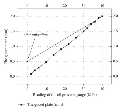
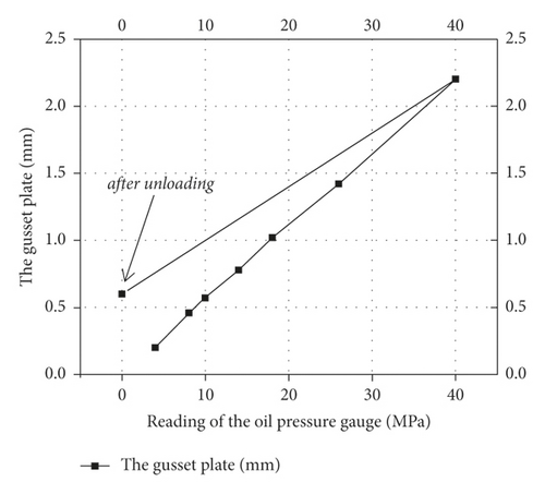
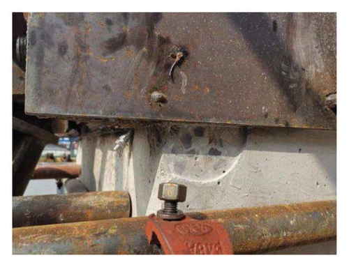
When the structure was first loaded to 3,276 kN, the relative displacement of the frame column and the gusset plate was 2 mm, and this value decreased to 0.5 mm after unloading. When the structure was loaded for the second time to 3,276 kN, the relative displacement was 2.2 mm and decreased to 0.6 mm after unloading. The anchorage bolts used for installation showed obvious deformation before and after unloading, indicating that the steel bolts were deformed by the shear force between the concrete specimen and the gusset plates. After unloading, the deformation of the steel bolts was reduced, which means that there was mainly elastic deformation with a small degree of plastic deformation. Figure 11 illustrates the relative displacement curve between the frame column and the gusset plate in the first test. Figure 12 shows the relative displacement curve of the frame column and the gusset plate in the second test.
In the disassembly process of the test piece, the steel pins can be easily extracted from the pinholes, and the small degree of deformation did not affect the disassembly operation. According to the observations in the two loading stages, it can be concluded that the connection between the frame columns and the gusset plates was safe and reliable. Figures 13 and 14 are the photos of the deformation of the anchorage bolts before and after loading.
4.3. Stress Analysis
The strain distribution of the members can be measured by the reading instrument, and the stress value can be calculated according to the elastic modulus and the measured strain value. Figure 15 shows the measured stress in the steel components during the first test loading process. As the pressure in the hydraulic jack increased, the stress of the steel components increased linearly, indicating that the component was in an elastic stage. During the loading process, the steel diagonal braces bore the pressure, while the prestressed steel tie rod bore the pulling force. The development of stress in the two steel diagonal braces was nearly the same. The maximum stresses at measurement points 1-1 and 2-1 are –93.16 MPa and −90.73 MPa, respectively, and the maximum stresses at measurement points 1-2 and 2-2 are −48.03 MPa and −36.10 MPa, respectively. The development of stress in the two prestressed steel tie rods was also identical, and the maximum stresses are 174.66 MPa and 178.07 MPa, respectively. The forces of the steel diagonal braces and the prestressed steel tie rods on both sides are balanced, which indicates that the support system was stable. The stress at measurement point 1-1 was 48% greater than that of measurement points 1-2, and the stress at measurement points 2-1 was 60% greater than that of measurement point 2-2, indicating that the stress distribution on the same location of the steel diagonal brace was uneven. The uneven stress distribution was caused by the effect of stiffening ribs. Therefore, it is recommended that the layout of stress measurement points in the actual project should be no less than two, and the location should be the same as the test.
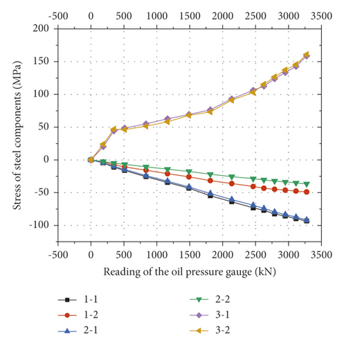
Figure 16 shows the stress of the steel component during the second loading process. The development of stress of the steel components was nearly the same as the first loading stage.
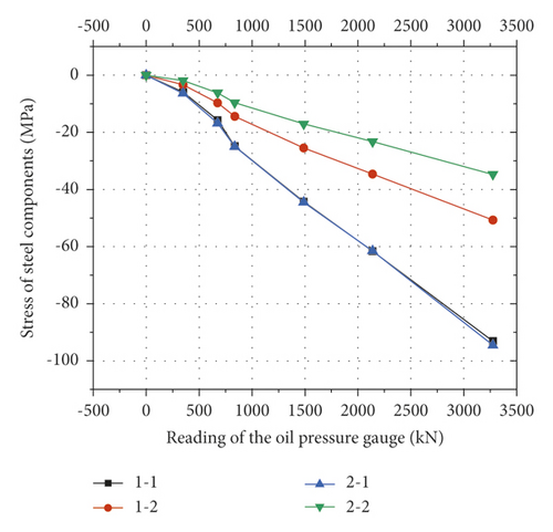
It can be seen from the two standard loading stages that when loaded to 3,276 kN, the maximum stress in the steel diagonal brace was 93.16 MPa, which was 28% of the yield strength; the maximum stress in the prestressed steel tie rod was 178.07 MPa, which was 19% of the yield strength. Therefore, the designed load-bearing capacity met the requirements for safe use.
4.4. Comparison of the Measured and Theoretical Axial Force
The ultimate load applied in the test was 3,276 kN, and the angle between the steel diagonal brace and the prestressed steel tie rod was 64 degrees. The internal forces of each component can be calculated according to Section 2.1.
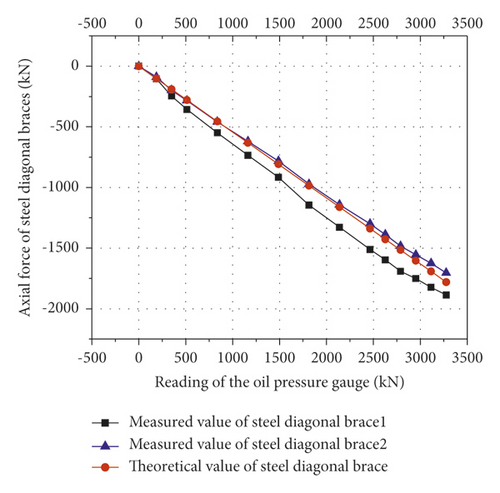
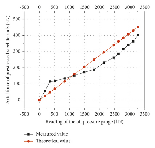
According to Figures 17 and 18, the measured values of the axial forces of the steel diagonal braces and the prestressed steel tie rods were consistent with the theoretical values, indicating that the force transmission path of the support system was the same as the theoretical assumption, and the unloading system was reliable. According to Figure 18, when the angle between the steel diagonal brace and the prestressed steel tie rod was constant, the strain reading of the hydraulic gauge and the tension force of the prestressed steel tie rod was in linear correlation. Therefore, in actual engineering, the unloading force value can be actively controlled through the angle between the steel diagonal braces and the prestressed steel tie rods and the tension of the prestressed steel tie rods.
5. Conclusion
- (1)
When the maximum design load was applied to the test specimen, no yielding in the steel bolts or large deformation in the structure were found, indicating that the connection between the frame column and the gusset plate was safe and reliable, and the theoretical calculation method can be used in actual engineering applications.
- (2)
After the testing was completed, the components of the test structure were disassembled. No visual crack was found on the surface of the concrete components, and also no large misalignment between the steel gusset plate and the concrete column was observed. In addition, the steel bolts deformed to a small degree. These phenomena indicated that the connections in the test were safe and reliable. The stability of the unloading system can meet actual engineering requirements.
- (3)
The measured axial forces of the test member were in good agreement with the theoretical values, and the deviation of the maximum load value was within 13%, indicating that with a fixed angle between the steel diagonal braces and the prestressed steel tie rods, the tension force of prestressed steel tie rods can be calculated by the unloading force. During the unloading process, the unloading force value can be actively controlled by adjusting the tension of the prestressed steel tie rods.
Conflicts of Interest
The authors declare that they have no known competing financial interests or personal relationships that could have appeared to influence the work reported in this paper.
Authors’ Contributions
Yongquan Wang contributed to methodology and formal analysis and wrote the original draft of the manuscript. Tianfu Li contributed to validation, visualization, and investigation. Kaifa Dong contributed to supervision and funding acquisition. Zhengxing Guo contributed to investigation, conceptualization, resources, and project administration. Jing Fu contributed to investigation.
Acknowledgments
This work was supported by school-level scientific research fund project of Nanjing Institute of Engineering (YKJ201928), the science and technology planning project of the Ministry of Housing and Urban Rural Development (2019-K-165), and the basic science (NATURAL SCIENCE) research project of Colleges and Universities in Jiangsu Province (21KJD560007).
Open Research
Data Availability
The data used to support the findings of this study are included within the article.


