Preparation and Gas Separation Performance of Polysulfone Mixed Matrix Membrane
Abstract
As an economical, environmentally friendly, and highly efficient separation technology, membrane separation is a popular research topic in the field of separation. Organic polymer materials have attracted considerable attention in membrane separation because of their controllable preparation processes, simple modification method, and high toughness. Taking polysulfone (PSF) as the substrate of gas separation membrane, we prepared the mixed matrix membrane jointly by using the solution casting method and by adding graphene oxide (GO) and carbon nanotubes (CNTs). On this basis, the permeability of the membrane for CO2 and N2 and the permeability coefficient of the mixed gas were studied. With the addition of CNTs and GO, the permeability of gas was significantly improved. At 0.2 MPa, permeability of CO2 increased from 553 Barrer to 975 Barrer, and permeability of N2 increased from 536 Barrer to 745 Barrer. The max ideal separation coefficient of CO2 and N2 is 1.94 at 0.1 MPa. Increasing of the content of carbon nanotubes can significantly improve the permeability coefficient of CO2, while the change of inlet side pressure has a great impact on the permeability coefficient of N2. At 0.1 MPa, when the ratio of CNTs to GO was 5 : 1, the ideal permeability coefficient of CO2/N2 was 1.94, whereas the ideal permeability coefficient of PSF membrane was 1.46. The above results of PSF/GO/CNT mixed matrix membrane lay a theoretical foundation for industrial application.
1. Introduction
With the continuous development of science and technology, products are also upgraded and improved continuously in the traditional manufacturing and metal smelting industries. As a result, the demand for energy in related industries is also increasing [1–3]. Traditional energy products are mainly nonrenewable fossil energy, such as oil and coal. However, due to its limited reserves, the demand is unable to adapt to the current growing energy demand, and with the current continuous exploitation, the sharp decline in reserves has led to widespread concern and worry. Therefore, researchers focus on the development of new energy and the recycling of energy by-products in the production process to solve the energy problem.
As an energy by-product, if the blast furnace gas produced in metal smelting can be recycled, then it can reduce the production cost of enterprises and save some energy, thereby facilitating green production. However, the main compositions of blast furnace gas are incombustible N2 and CO2, and the content of combustible CO is low in blast furnace gas. As a result, its calorific value is low, and it is difficult to recycle. Searching a feasible and effective way to separate N2 and CO2 from blast furnace gas is a feasible way to improve the utilization rate of blast furnace gas [4, 5].
The common gas separation methods include adsorption method, absorption method, membrane separation, and condensation gasification. Among them, because different gas molecules have different diffusion rates passing through membranes under external pressure, the membrane separation method can be used to separate gas. Compared with other methods, the membrane method has many advantages, such as being economical and environmentally friendly, having low energy consumption, and easy modification. Therefore, the method has promising research prospects in the field of gas separation at present [6–10]. Based on differences in materials, gas separation membrane can be divided into various types, such as inorganic, organic, and mixed matrix. The inorganic membrane has zeolite, molecular sieve, graphene, metal-organic framework, and other inorganic materials with porous structure as the main body [11–14], and it conducts gas permeation and separation based on the pores of the materials. The membrane has high temperature resistance, stable chemical properties, high strength, and adjustable pore size. Lin et al. [15] prepared zeolite/carbon hybrid membranes and studied the permeability and ideal separation performance of different gases. Among these gases, the permeability coefficients of CO2 and N2 were 564 Barrer and 15 Barrer, respectively. The ideal separation coefficients of CO2/N2 could reach 37.7 (the diameter of ZSM-5 doped particle was 0.2 μm). Japip et al. [16] prepared 6FDA-Durene/ZIF-71 mixed matrix membrane and studied the effect of ZIF-71 of different particle sizes on the selectivity of gas. The selectivity of O2/N2, CO2/N2, and CO2/CH4 could reach 3.35, 14.7, and 17.0, respectively. Although molecular sieve has shown excellent characteristics in the field of gas separation, its application in practical production is limited due to the complex preparation process, the preparation process is easy to cause adverse effects on the environment, and it is of high cost.
In 1991, a new type of carbon material, a 1D tube known as a carbon nanotube, was founded by Dr. Iijima from Japan NEC Company. The CNT comprises a curl of graphene around a central axis [17]. In recent years, with the continuous research on CNTs, CNTs have been shown to possess good thermal, electrical, optical, and mechanical properties [18]. With good heat conduction and conductivity, high hardness, high strength, large specific surface area, and high length-diameter aspect ratio [19], the nanotube can be compounded with polymer materials and inorganic nonmetallic materials and applied to many fields, including water treatment, gas separation, energy, and sensors. The relevant research is also found in gas separation.
Graphene, as a 2D, is composed of carbon atoms by sp2 hybridization, which is a compact lamellar structure in the form of a six-membered ring. It has a large specific surface area due to its unique 2D plane structure [20]. At the same time, the layers are connected by van der Waals force. With a small acting force, the relative movement among layers is easily produced [21]. GO is obtained by the oxidation of graphene. The lamellar structure is loaded with oxygen-containing groups, thereby increasing the gap among layers and making obtaining graphene with fewer layers easier [22, 23]. At the same time, owing to the introduction of oxygen-containing groups, the hydrophilicity of graphene is increased, thereby providing a site for further modification. With these excellent properties, GO has also been applied to gas separation [24]. Li et al. [25] prepared a GO film with a thickness of only 1.8 nm and explored gas separation performance. The selectivity of H2/CO2 could reach 3400. Yang et al. [26] prepared the separation film for separating H2 and CO2 by using self-assembly technology. Its selectivity exceeded 300. Koenig et al. [27] prepared a GO film for separating H2 and CH4 by using oxygen etching. Its selectivity could reach 104. Kemal et al. [28] prepared a separation membrane with a bimolecular graphene layer. Its selectivity for H2/CO2 was 4.6. Kim et al. [24] deposited GO on the surface of the substrate by chemical vapor deposition and prepared the separation membrane. Its selectivity for O2/N2 could reach 6, and the selectivity of GO/polyethersulfone composite film prepared by the spin coating method for CO2/N2 could reach 20. Shen et al. [29] prepared a GO-PEBA membrane, and its selectivity for CO2/N2 could reach 91. The selectivity of the ZIF-8@GO inorganic separation membrane prepared by Huang et al. using the layer-by-layer method for H2/N2 could also reach 91 [30]. Athanasekou et al. [31] prepared a GO membrane by using AAO as the base material and studied the membrane’s permeability to gas and water. The prepared membrane has good permeability to water and helium but relatively weak permeability to N2.
Inorganic separation membranes commonly used in gas separation have some disadvantages, such as high preparation cost, high brittleness, and complex preparation process. Compared with inorganic separation membrane, organic separation membrane, for example, polyethersulfone membrane, has the advantages of low preparation cost, simple film-forming process, strong flexibility, and so on, but also has the disadvantage of higher separation efficiency than inorganic membrane, which restricts the development of pure organic membrane. Therefore, the mixed matrix membrane combining organic and inorganic materials has become a research hotspot in recent years. Orooji et al. [32] reported a kind of polyethersulfone membrane with nanostructured mesoporous carbon composited that showed adding the mesoporous carbon nanoparticles improved the pure water flux. Orooji’s team using polyethersulfone prepared ultrafiltration membrane, and results showed that adding vermiculite can improve mixed matrix membrane flux to pure polyethersulfone membrane [33].
In this paper, the mixed matrix membrane (MMM) is prepared by taking PSF, GO, and CNTs as raw materials. The prepared materials are characterized by scanning electron microscopy (SEM), transmission electron microscopy (TEM), X-ray diffraction (XRD), Fourier infrared spectroscopy (FTIR), and Raman spectroscopy. The permeability of CO2 and N2 with a single component is tested by using laboratory self-assembly devices, and the ideal separation coefficient is calculated.
2. Experiments and Methods
2.1. Materials and Reagents
SWCNTs were purchased from Shenzhen Nanotech Port Co., Ltd. (China), which was treated with mixed acids (volume ratio H2SO4 : HNO3 = 3 : 1). Natural flake graphite (12,000 mesh) was purchased from Qingdao Tianshengda Graphite Co., Ltd. (China). H2SO4, HNO3, and KMnO4 were purchased from Big Alum Chemical Reagent Factory (China). Ultrapure water was used for the preparation of solution. All of the chemicals were of analytical grade (>99.7%) without further purification. N2, CO2, and mixed gas (N2: 60%, CO2: 20%, and CO: 20%) were purchased from Shanghai Tonghui Special Gas Co., Ltd. Polysulfone (PSF) was purchased from Aldin Co., Ltd.
2.2. Preparation of MMMs
2.2.1. Preparation of GO
With natural flake graphite as a raw material, GO is prepared by the existing improved Hummer method. Graphite is first treated with mixed acid, and then, GO is prepared by three stages of reaction at low, medium, and high temperature. Details may be found in the articles of the research team [34].
2.2.2. Preparation of PSF Mixed Matrix Membrane
Different qualities of PSF (0.5, 0.4985, 0.497, and 0.4945 g) are weighed and placed in a flat-bottomed flask with 10 mL DMF. The mixture is stirred magnetically at 80°C. As a result, PSF is completely dissolved in DMF. Then, GO and CNTs are added into 5 mL DMF. Ultrasound is conducted for 3 h to ensure complete dispersal. Under ultrasonic conditions, the completely dispersed GO/CNTs are added into the PSF solution slowly, and the ultrasound is conducted continuously for 4 h to ensure that GO/CNTs are completely dispersed in the PSF solution. The solution is heated at 80°C for 10 min and then poured into a dish preheated for 30 min in a vacuum drying oven at 80°C to heat and dry for 12 h. As a result, the mixed matrix membranes mixed with different contents of CNTs and GO are obtained. The ratio of CNT and GO is 0, 2 : 1, 5 : 1, and 10 : 1, respectively.
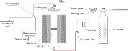
2.3. Experimental Apparatus for Gas Separation
2.4. Characterization Techniques
Fourier transform infrared spectroscopy (FTIR, type Nicotct 5700) was used to characterize the related groups of PSF and the treated carbon materials. Scanning electron microscopy (SEM, type JEM-6700F, operating at 0.5-30 kV) and transmission electron microscopy (TEM, type JEM-2010, operating at 200 kV) were used to analyze the morphology of the prepared GO and purified CNTs. X-ray diffraction (XRD, type D8/AXS, operating at 60 kV) and Raman spectroscopy (type inVia) were used to relatively characterize the existence of GO and CNTs in the mixed matrix membrane. TGA (type NETZSCHSTA-449F3) is used to analyze the thermal stability of prepared gas separation membranes under the N2 atmosphere from room temperature to 800°C at a heating rate of 20°C/min.
3. Results and Discussion
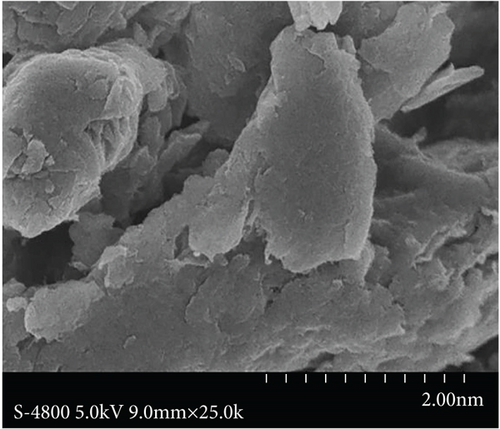
3.1. SEM
Figure 2 shows the surface morphology of CNTs and GO composites. Figure 2(a) clearly shows that the purified CNTs are scattered without obvious agglomeration, and the length of CNTs was shortened. Figure 2(b) shows the surface morphology of prepared GO, with obvious lamellar structure and fewer stacking layers, thereby indicating that GO is successfully prepared.

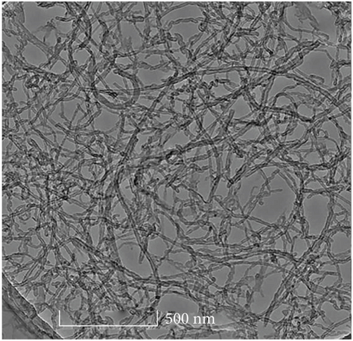
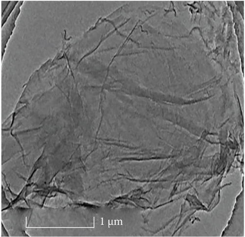
3.2. TEM
Figure 3(a) clearly shows hollow tubular CNTs did not have impurities and obvious agglomeration and showed good dispersion. Figure 3(b) shows the lamellar structure of GO has fewer stacking layers with a good separation effect.
3.3. FTIR
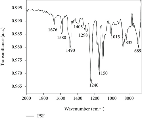
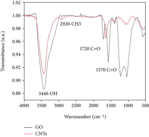
In Figure 4(a), a small peak occurs at 2965 cm-1, which may be the stretching vibration peak of C-H due to the wide peak shape. The peak at 1676 cm-1 is clear, and no other peaks are nearby, thereby indicating that it is the C=O stretching vibration peak of -COOH, whereas the peaks at 1580 and 1490 cm-1 are the characteristic absorption peaks of the benzene ring in the PSF structure [36, 37]. The peak at 832 and 689 cm-1 also proves the existence of the benzene ring. The peak at 1405 cm−1 corresponds to the bending vibration peak of the O-H bond. The peaks at 1298 and 1150 cm-1 should be the absorption peak of the sulfone group (O=S=O) in the PSF structure. The peak at 1240 cm-1 is the strongest in the spectrum, thereby indicating that it stretches the vibration peak of the C-O group in the PSF structure. The peak at 1015 cm−1 may be the absorption peak of the C-O-C group. Figure 3(b) shows the FTIR spectrum of GO and CNTs. The GO and CNT spectra show a strong -OH vibration peak at 3440 cm-1, thereby indicating that the surface of the prepared GO and the surface of CNTs treated by mixed acid are loaded with -OH. The peak at 2920 cm-1 is a vibration peak of -CH3, and that at 1720 cm-1, it is a C=O vibration peak, indicating the introduction of carboxyl, and that at 1570 cm-1, it is a C=C vibration peak. Owing to the existence of hydroxyl and carboxyl groups, GO was successfully prepared from graphite, and CNTs were successfully purified by mixed acid treatment [38–40].
3.4. XRD
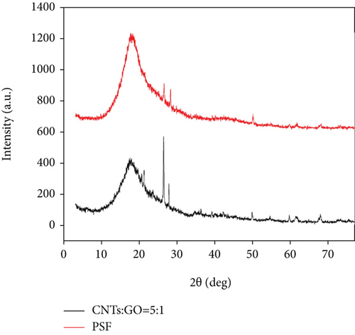
Figure 5 shows that the pure PSF membrane has a very strong peak at 18°. This peak is the crystal plane diffraction of PSF, thereby indicating that the pure PSF has a certain degree of crystallinity. After the doping of CNT and GO, this diffraction peak obviously remains, indicating that the doping did not destroy the structure of the polymer itself. Compared with the pure PSF, the diffraction peak moved towards a low angle (blue shift), indicating that the addition of CNTs and GO increased the spacing of the molecular chain, although the peak strength decreased. The addition of CNTs and GO increased the degree of freedom and free volume of the polymer chain, decreased the crystallization behavior caused by the aggregation and stacking of molecular chains, and lowered the crystallinity of the mixed matrix membrane itself [41, 42]. Compared with the pure PSF membrane, because of the addition of CNTs and GO, two strong peaks existed near 26.8°. These peaks occurred in the pure PSF and mixed matrix membranes, and the peak in the mixed matrix membrane had higher strength. At the same time, CNTs have characteristic peaks here, thereby proving the existence of CNTs in the mixed matrix membrane [34, 43].
3.5. Raman Spectroscopy
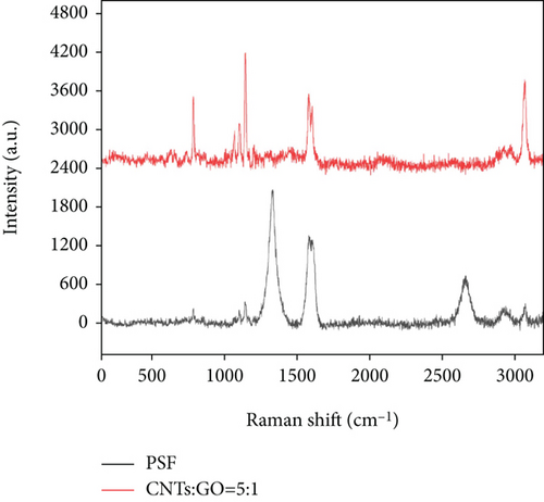
CNTs and GO in the prepared mixed matrix membrane can be analyzed by Raman spectroscopy. Figure 6 shows that the strong peaks occurred at 1147 cm-1, 1583 cm-1, and 3050 cm-1 correspond to PSF, respectively, which is basically consistent with previous reports. The comparison between PSF and PSF/GO/CNT membrane shows that while oxygen-containing groups are introduced in the preparation of GO and CNTs and chemical treatment, some structural defects and sp2 hybridization of C atom are caused. Thus, a D peak is present at 1365 cm-1, and a G peak is at 1660 cm-1. However, a 2D peak of GO and CNTs is at 2600 cm-1. The appearance of D, G, and 2D peaks of GO and CNTs proved the dispersion of GO and CNTs in PSF [43–47].
3.6. TGA
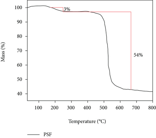
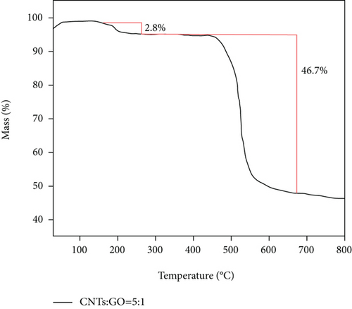
Figure 7 shows that there are two stages of mass reduction in pure PSF membrane and PSF/GO/CNTs. The first stage of weightlessness occurs at 250°C, which is mainly caused by the fracture of polymer molecular chain at this temperature. With further increase of temperature, the second stage of weightlessness appears around 520°C. It indicates that the polymer is decomposed and carbonized at this temperature. And the molecules are removed in the form of small molecular compounds, so that the mass of membrane is significantly reduced. The similar curves also show that the second stage of weightlessness of the mixed matrix membrane is obviously smaller than that of pure PSF membrane, and the remaining mass is also more than that of the PSF membrane. Thus, the weight loss near 520°C is due to the carbonization and decomposition of the membrane.
3.7. The Permeability of CO2 with Different Pressure
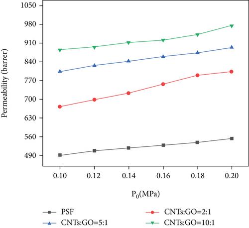
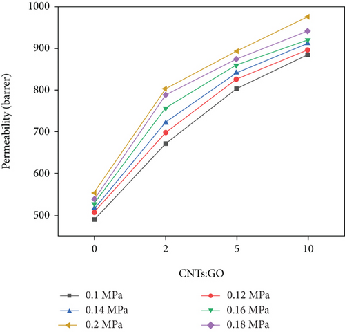
Figure 8 shows that intake pressure and addition of CNTs/GO have a certain influence on the permeability coefficient of CO2. The increase in the permeability coefficient can be significantly improved by increasing the intake pressure or the addition of CNTs. Increasing the content of CNTs can improve the permeability of CO2 more obviously than increasing the intake pressure. At 0.1 MPa, the permeability coefficient of CO2 is increased by 303 Barrer, from 491 Barrer (pure PSF membrane) to 884 Barrer (CNT : GO = 10 : 1); at 0.2 MPa, it is increased by 422 Barrer from 553 Barrer (pure PSF membrane) to 975 Barrer (CNTs : GO = 10 : 1). If only intake pressure is changed from 0.1 MPa to 0.2 MPa, and the ratio of CNTs to GO remains unchanged, then permeability coefficient of CO2 is increased by 131 Barrer at most. The permeation of CO2 through this membrane is positively correlated with the pore content of the membrane. Given that CNTs are hollow tubular structures, the increase of CNTs to GO ratio provides more channels for CO2 diffusion and permeation, thereby improving the surface area of the membrane and promoting the probability of CO2 diffusion through the surface. As a result, the permeability coefficient of CO2 is significantly increased.
3.8. The Permeability of N2 with Different Pressure
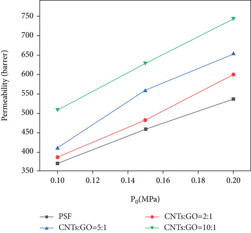
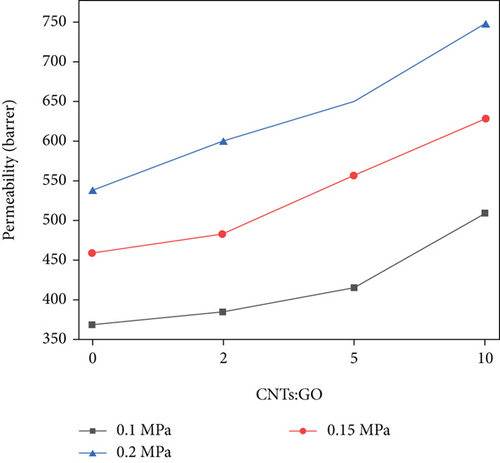
Figure 9 shows the influence of different intake pressures and the ratio of CNTs to GO on the permeability coefficient of N2. The same as CO2, the permeability coefficient of N2 can be improved by increasing the intake pressure and the ratio of CNTs to GO. At 0.1 MPa, by changing the addition of CNTs, the permeability coefficient of N2 is increased by 123 Barrer from 385 Barrer to 508 Barrer. At 0.2 MPa, the coefficient is increased by 209 Barrer from 536 Barrer to 745 Barrer. If the ratio of CNTs to GO remains unchanged, and the intake pressure is changed from 0.1 MPa to 0.2 MPa, then the permeability of N2 is increased by 237 Barrer at most. Increasing of the intake pressure more obviously improved N2 permeability than that of the ratio of CNTs to GO. However, after increasing the ratio of CNTs to GO, the permeability coefficient of N2 is significantly increased, which is significantly different from the permeability of CO2. The permeation mechanism of N2 is different from that of CO2 in terms of passing through this mixed matrix membrane. Given that the molecular dynamic diameter of N2 (0.364 nm) is larger than that of CO2 (0.33 nm), N2 may focus on Knudsen diffusion. Its diffusion rate is directly proportional to the pressure difference on both sides of the membrane. Owing to the increase in the ratio of CNTs to GO, the collision probability occurs between N2 molecules and pore wall. Therefore, the collision between gas molecules and pore wall is much more than that between molecules, thereby improving the permeability coefficient of N2.
3.9. The Separation Performance of CO2 and N2
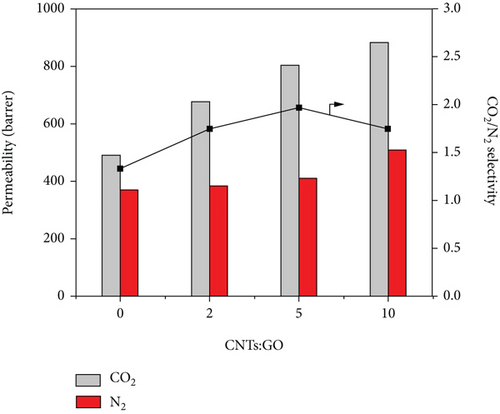
Figure 10 shows that at 0.1 MPa, the permeability coefficient of CO2 is obviously higher than that of N2. With increasing ratio of CNTs to GO, the permeability coefficient of CO2 increased more obviously than that of N2. However, when the ratio of CNTs to GO increased from 5 : 1 to 10 : 1, the increase in the permeability coefficient of N2 was more than that of CO2. The number of pores also played an important role in improving the permeability of N2. Therefore, ratio of CNTs to GO is less than 5 : 1, and the effect of pore numbers on permeability for CO2 was more obvious. With further increase in the ratio, the effect of pores on N2 became more obvious. At 0.1 MPa, when the ratio of CNTs to GO was 5 : 1, the ideal permeability coefficient of CO2/N2 was 1.94, whereas the ideal permeability coefficient of PSF membrane was 1.46. The addition of CNTs and GO can effectively improve the selectivity of the membrane.
The comparison of this paper with the published articles is shown in Table 1. The separation membrane prepared by this research team greatly improved the permeability of CO2 and N2. GO and CNTs can effectively improve the permeability of gas, thereby providing a direction and possibility for exceeding trade-off upper limits.
4. Conclusions
In this paper, the improved Hummer method is used to prepare GO from natural flake graphite, and CNTs are treated by the mixed acid method. Taking the two carbon materials as additives and PSF as the substrate, the mixed matrix membrane was prepared. Compared with the pure PSF membrane, the gas permeability was greatly improved after adding CNTs and GO. At the same intake pressure, the difference in the permeability of CO2 between PSF and PSF/GO/CNTs can be 422 Barrer at 0.2 MPa at most, and that of the permeability of N2 can be 209 Barrer. The permeability of CNTs for CO2 was improved more significantly than that of N2. Increasing the intake pressure was more effective for improving the permeability of N2. At 0.1 MPa, when the ratio of CNTs to GO was 5 : 1, the ideal permeability coefficient of CO2/N2 was 1.94, whereas the ideal permeability coefficient of PSF membrane was 1.46.
Conflicts of Interest
The authors declare that there are no competing interests regarding the publication of this paper.
Acknowledgments
The authors are grateful for the financial support from the National Natural Science Foundation of China (51764039); Basic Public Welfare Research Project of Zhejiang Province (LQ19E040006); State Key Laboratory of Advanced Processing and Recycling of Non-Ferrous Metals, Lanzhou University of Technology (SKLAB02019013); Doctor Research Foundation of Lanzhou University of Technology (061702); and Project of Hongliu support discipline of Lanzhou University of Technology.
Open Research
Data Availability
All the data supporting the results are shown in the paper and can be applicable from the corresponding author.


