UAV Path Planning Based on Improved A∗ and DWA Algorithms
Abstract
This work proposes a path planning algorithm based on A∗ and DWA to achieve global path optimization while satisfying security and speed requirements for unmanned aerial vehicles (UAV). The algorithm first preprocesses the map for irregular obstacles encountered by a UAV in flight, including grid preprocessing for arc-shaped obstacles and convex preprocessing for concave obstacles. Further, the standard A∗ algorithm is improved based on UAV’s flight environment information and motion constraints. Further, the DWA algorithm’s limitations regarding local optimization and long planning time are mitigated by adaptively adjusting the evaluation function according to the UAV’s safety threshold, obstacles, and environment information. As a result, the global optimal path evaluation subfunction is constructed. Finally, the key points of the global path are selected as the subtarget points of the local path planning. Under the premise of the optimal path, the UAV real-time path’s efficiency and safety are effectively improved. The experimental results demonstrate that the path planning based on improved A∗ and DWA algorithms shortens the path length, reduces the planning time, improves the UAV path smoothness, and enhances the safety of UAV path obstacle avoidance.
1. Introduction
Unmanned aerial vehicles (UAVs) are widely used in industry, life sciences, logistics, and other fields. In recent years, path planning has emerged as a critical problem for UAVs. UAV path planning sets the start and end points in the UAV environment map and plans a collision-free, optimal, and safe path using a relevant path planning algorithm.
At the core of the UAV, path planning is the path planning algorithm. Based on the employed planning scenarios, path planning can be divided into global path planning and local path planning. Global path planning utilizes the environment map with known obstacles, while local path planning relies on the environment map with unknown obstacles. The main algorithms used in global path planning are, for example, A∗ [1, 2], Dijkstra [3], and RPT [4]. The local path planning algorithms include dynamic window algorithms (DWA) [5, 6], artificial potential field method (APF) [7, 8], and ant colony algorithm (ACO) [9]. Many scholars researching the UAV path planning assume that the obstacles in the UAV environment are regular in shape (e.g., circle or rectangle). However, disregarding the obstacles’ irregularities prevents accurate representation and planning of the UAV flight path.
Lyu et al. proposed a path planning algorithm based on graph search. The improved algorithm uses the Floyd algorithm to weight different paths, which greatly reduces the number of path points and effectively improves the smoothness of the path [10]. Turker et al. study the problem of UAV radar evasion by regarding a radar as a circular no-fly zone and realizing the path planning on a two-dimensional plane via the simulated annealing algorithm [11]. Yao and Wang propose an adaptive ant lion optimization algorithm for path planning [12]. The authors verified the proposed algorithm’s effectiveness but only considering circular and rectangular no-fly zones. Thus, it is more suitable for maps with ideal obstacle boundaries [12]. Similarly, Xu et al. model obstacles as circular no-fly zones and optimize the planning path based on the Laguerre diagram [13]. Boulares and Barnawe et al. proposed a regression algorithm, which used the predicted trajectory of the missing target to plan the path of the UAV search task [14]. Belkadi et al. proposed a distributed UAV trajectory generation strategy, which solved some problems in a group of UAV control and can be applied to large-scale search, monitoring, inspection, and rescue [15]. Huang et al. proposed a coordinated path planning method for multiple UAVs based on k-order smoothing and constructed a complex environment composed of multiple threat sources. Using the improved ant colony algorithm, a k-order smoothing algorithm is proposed to obtain a more flexible path [16].
DWA is a commonly used local path planning algorithm, which has good obstacle avoidance ability. However, it is prone to falling into a local optimum and not reaching the specified target point. Moreover, the increase in complexity of the UAV application scene and environment may render the standard DWA incapable of solving the complex path planning problem. Consequently, DWA typically needs to be improved through combination with global path planning algorithms.
According to Yulong et al., in solving the UAV path planning problem, the decoupling strategy is introduced, and the messenger UAV path planning problem is described as a dynamic traveling salesman problem with neighborhood [17]. Huo et al. proposed a hybrid differential symbiotic organisms search algorithm (HDSOS), which combines the differential evolution mutation strategy with the improved symbiotic organisms search (SOS) strategy [18]. The algorithm maintains the systems’ local search capability while simultaneously achieving a good global search performance [18]. To solve the problem of UAV route planning under different threats in a complex environment, Phung and Ha proposed a particle swarm optimization algorithm that not only is superior to the classical particle swarm optimization, phase swarm optimization, and quantum swarm optimization but also outperforms the genetic algorithm [19]. Jeauneau et al. proposed two methods for UAV path planning in a real 3D environment. A single path is provided based on the A-star method, and multiple paths are provided by the genetic algorithm using Pareto Frontier (PF). The generated paths must meet the dynamic characteristics of vehicles [20].
When establishing the environment, the studied literature regards the planning space as too perfect, rendering it impractical. Such path planning algorithms are suitable for simple environmental maps. Considering that most obstacles in the real environment are irregular in shape and UAVs are often regarded as particles, the direct application of the listed methods requires expanding the range of obstacles and affects the planning results. Thus, an improvement is required.
To support path planning in complex environments, this paper first studies the irregular obstacles that a UAV may encounter in a flight. Such a process includes grid processing of arc obstacles and convex processing of concave obstacles. Next, the cost function is improved by using the obstacle weight coefficient in the environment map. The standard A∗ algorithm is advanced by incorporating the UAV motion constraints and a safety threshold. While considering the incompatibility of speed and safety in DWA, the algorithm is improved through an adaptive speed evaluation function that considers the density of obstacles and the safety threshold. Finally, critical nodes in the global path planning are taken as local subobjective points to improve the algorithm while relying on the improved A∗ and DWA algorithms. As a result, the optimal, shortest path with greater smoothness from the start to the end is planned.
2. Environment Modeling and Obstacle Pretreatment
Most of the obstacles in the flight environment of UAV are irregular in shape, and UAV is often regarded as a particle. The UAV flight environment is directly regarded as a regular map, which is easy to expand the range of obstacles and affect the planning results, so the environment map is first processed.
2.1. Grid Method for Airspace Modeling
- (1)
Starting point and target point
- (2)
UAV’s physical performance limitations
- (3)
Information regarding irregular obstacles
Further, note that a cruising UAV can be regarded as a particle.
2.2. Gridding Treatment of Arc Obstacles
- (Step 1)
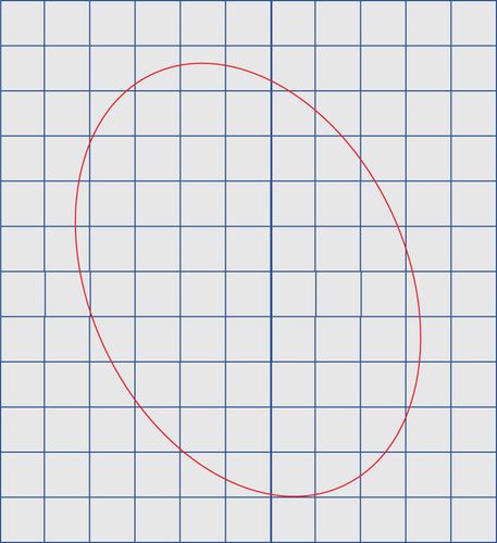
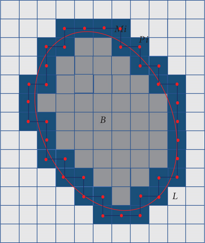
Determine the outer edge line (L) of the arc obstacle (B). Further, determine the grid position of each arc line Li, and denote the marked grid elements as Mi. Regard the centers of the marked grid elements as the locating points, and denote them as Pi, i = 1, 2, ⋯, n, where n is the number of segments of the outer edge line
- (Step 2)
Connect the locating points P1, P2, ⋯, Pn, P1, obtaining the polygon P1P2 ⋯ PnP1 by regarding each M1, M2, ⋯, Mn, M1 clockwise from the starting marked grid element. Consequently, obtain the result of obstacle B polygon processing, B ≈ P1, P2 ⋯ PnP1
2.3. Convex Filling of Concave Polygon Obstacles
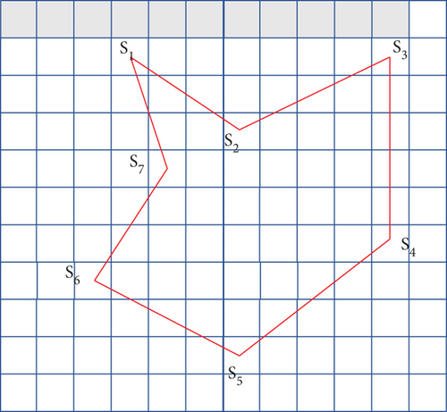
The convex filling process commences by determining the coordinates of each polygon vertex in the grid graph. Starting from the first grid element, the polygon vertices are denoted S1, S2, ⋯, Sm, where m is the number of vertices of the polygon. If the inner angle formed by the two adjacent edges is greater than 180 degrees, the corresponding vertex Si is a concave point. Otherwise, the vertex is a convex point. In the path-searching algorithm, if the path point falls into the concave area, the next path point must be placed outside the concave area to complete the flight mission. Concave areas affect the UAV path quality and increase the number of invalid path points, affecting the solution speed.
- (Step 1)
Determine the concave polygon’s vertices S1, S2, ⋯, S7, and judge the concavity and convexity of each vertex according to the concavity and convexity rules (Figure 2(a))
- (Step 2)
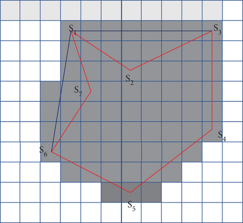
Based on Step 1, start from the starting convex point S1, and connect other convex points clockwise, yielding the polygon S1S3S4S5S6S1 as the convex result (i.e., F ≈ S1S3S4S5S6S1). Then, the obstacles are gridded according to the arc obstacles, as shown in Figure 2(b)
3. Improved A∗ Algorithm
There are many turning points and large angles in the path planned via the standard A∗, which is not conducive to a UAV flight. Thus, this work improves the standard A∗ according to the motion characteristics and environmental information of UAVs in flight.
3.1. Improvement of the Heuristic Function
The evaluation function of A∗ is composed of a cost function g(n) and a heuristic function h(n), and the algorithm’s optimal searching performance depends on the selection of the heuristic function. The improved A∗ algorithm introduces the obstacle weight coefficient into the heuristic function, as shown in Equation (2). The obstacle weight coefficient expresses the grid map complexity, and the environmental information is analyzed.
According to equation (2), the improved algorithm sets the weight of the adaptive heuristic function. When the obstacle weight coefficient K is small, the weight of the heuristic function is increased. The A∗ algorithm reduces the search space, improves the speed of path planning, and effectively reduces the inflection points and turning points of the path. When the obstacle weight coefficient is large, reduce the weight of the heuristic function and increase the search space to avoid the algorithm falling into local optimization.
3.2. Determining the UAV Safety Distance
The improved A∗ sets the safety distance between the path node and the obstacle to prevent the UAV from colliding with the obstacle. As shown in Figure 3, the vertical distance OE (the vertical distance from point O to line KG) from the obstacle to the path is compared with the preset safety distance to judge whether the planned path is safe and feasible.
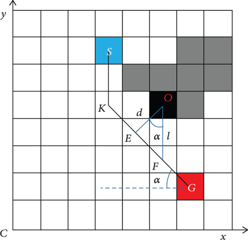
The distance d from the obstacle to the path is calculated following equation (6). Let D denote the safety threshold. Then, distance d is compared with the safety distance D to determine whether the path can be used as an alternative path. If d ≤ D, the path is abandoned. Then, according to the improved A∗ algorithm, continue to search for new nodes until the optimal path is found. Otherwise (i.e., when d > D), the path is selected.
3.3. Path Smoothing Optimization
As emphasized previously, because the algorithm search principle and subnode search direction of standard A∗ algorithm are 8-node expansion direction, the path planned by the algorithm is not conducive to UAV flight. Further, path planning takes a long time, and the search route is close to the obstacle’s edge. The improved A∗ algorithm combines the Floyd algorithm with the A∗ algorithm, effectively reducing the number of turning points in the UAV path [22], improving the UAV movement efficiency, and meeting the UAV application requirements. Considering the kinematic model to judge whether the derived path is more suitable than the original regarding distance, time, and angle, the algorithm optimization path comparison is shown in Figure 4.
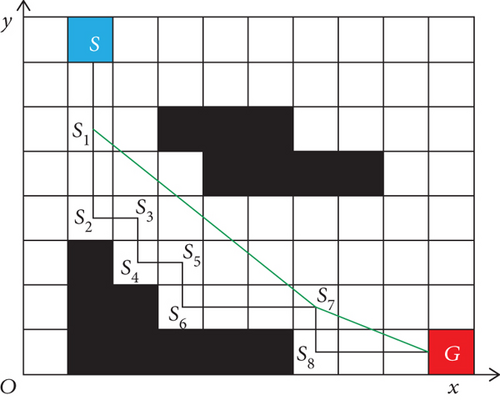
As shown in Figure 4, the standard A∗ algorithm yields the path (S, S1, S2, S3, S4, S5, S6, S7, S8, G). This path has many inflection points, resulting in poor smoothness.
The Floyd smoothing algorithm can be used to eliminate redundant path nodes, effectively reducing the number of turns and optimizing the path length. The Floyd algorithm combines the UAV motion characteristics to improve the path smoothness. By judging whether there is an obstacle between the two nodes, as well as considering the security threshold D and the distance d between the two nodes connected to the obstacle, one can determine whether the path is feasible. Finally, the path (S, S1, S7, G) is obtained.
Building on the described principles, the standard A∗ algorithm and the improved A∗ algorithm are simulated and verified, and the obtained paths are shown in Figure 5.
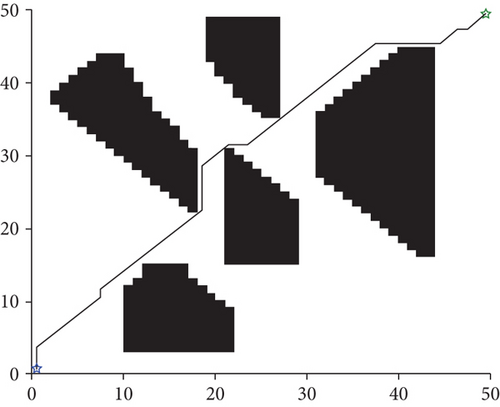
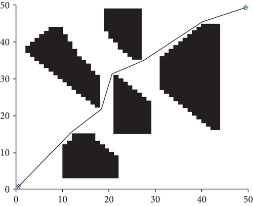
The path planned by the standard A∗ algorithm (Figure 5(a)) has many redundant nodes and road sections, and its turning angles are large. As a result, the path length is 75.1543 km, which is suboptimal (i.e., not the shortest) and does not conform to the UAV operation rules. In contrast, the path planned by the improved A∗ algorithm (Figure 5(b)) is relatively smooth, and its length equals 72.0735 km. Thus, the improved algorithm achieves a 4.1% improvement in the path length. Moreover, a certain safety distance can be observed between the global path and the obstacles, which is more conducive to the UAV movement.
4. Improved DWA
In the local path planning, the standard DWA algorithm only specifies the position of the target point, failing to consider unknown obstacles. Moreover, when there are many obstacles, the path planning algorithm easily falls into the local optimum, resulting in an increase in the global path length. The improved A∗ algorithm regards the global path’s key nodes as subtarget points of the local path. Then, the environmental information is used to adjust the weight coefficient in the speed evaluation subfunction. Consequently, UAVs can successfully avoid unknown obstacles and reach the target point safely and efficiently.
4.1. Motion Model
4.2. UAV Speed Sampling
DWA models the UAV’s obstacle avoidance problem as an optimization problem with velocity constraints, including nonholonomic constraints, environmental obstacle constraints, and UAV dynamic constraints.
The DWA’s velocity vector space diagram is shown in Figure 6. The abscissa and ordinate represent the UAV angular velocity (w) and the UAV linear velocity (v). In accordance, vmax and vmin denote the maximum and minimum linear velocity, whereas wmax and wmin are the maximum and minimum angular velocities. The whole area is Vs, the white area (Va) represents the safe area, and Vd is the UAV speed range considering motor torque limitation in the control cycle. Finally, Vr is the UAV dynamic window determined by the intersection of the listed three sets.
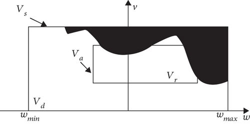
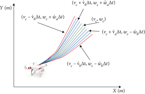
The continuous velocity vector space (Vr) is discretized based on the number of linear velocity and angular velocity samples to obtain the discrete sampling points (v, w). For each sampling point, the UAV motion trajectory at the next moment is predicted using the UAV kinematics model (see Figure 7).
4.3. Adaptive DWA Algorithm
DWA controls the speed using the weight coefficient (β) in the speed evaluation subfunction. If β is too large, the UAV is very fast, but the safety is reduced. In contrast, if β is too small, the UAV’s speed is insufficient, but the safety is very high. Considering the relationship between UAV safety and speed, the improved DWA algorithm adaptively calculates the speed evaluation function’s weight coefficient while relying on environmental information. The UAV’s sensors are utilized to collect environmental information. The obstacle density and the distance between the UAV and the obstacles in the environment are used to calculate the speed evaluation function’s weight coefficient. The weight coefficient is adjusted to achieve higher speed in safe areas, whereas the speed is reduced in dangerous areas to enhance UAV flight safety.
4.3.1. Safety Threshold for Obstacle Detection
The distance between different obstacles serves to judge whether the UAV can pass through the obstacles. When L equals more than twice the two obstacles’ expansion distance, the UAV can pass between the obstacles.
4.3.2. Adaptive Function Calculation
If the UAV flight is within the safety threshold (i.e. the shortest distance Dmin between the UAV and the obstacle is less than the UAV safety threshold, the UAV flight speed was reduced (according to the nature of exponential function). If the UAV flies outside the safety threshold (i.e., the shortest distance Dmin between the UAV and obstacles is greater than the UAV safety threshold), the UAV flight speed is set according to the maximum speed weight, as shown in equation (14).
β0 is the maximum speed weight, Ds is the safety threshold, and η is the adjustment parameter. When Ds is greater than Dmin, the speed weight increases monotonically with the input Dmin, i.e., βr = β0. When Ds is less than Dmin, the speed weight is an exponential function of Ds and Dmin. As the ratio of Dmin and Ds decreases, βr increases. Otherwise, if Dmin/Ds increases, βr decreases.
4.3.3. Improved Evaluation Function
The standard DWA algorithm does not refer to the UAV’s global path but only plans the target points. Moreover, in the case of numerous obstacles, the process easily falls into a local optimum, yielding a larger path distance. The dist(v, w) weight in the evaluation function moves the UAV trajectory away from obstacles, resulting in a locally optimal trajectory and increasing the global moving distance. If the corresponding weighting coefficient (γ) is directly reduced, the UAV faced with the unknown obstacles cannot avoid them in time, leading to the collision.
5. Fusion Algorithm
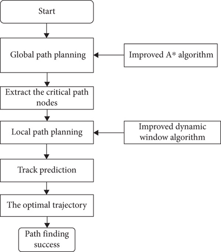
This work combines global and local path planning. The key nodes on the global path are regarded as the subtarget points of the local dynamic path to ensure the dynamic path planning’s global optimality. The global path planning is carried out on the known map. The UAV’s trajectory information in the next period is calculated based on the UAV’s current linear speed and angular speed. Each UAV trajectory is predicted using the evaluation criteria, and the unreasonable trajectories or those where an obstacle is encountered are discarded. The path evaluation subfunction evaluates a certain path, and the evaluation values are accumulated. The trajectory with the lowest cost is deemed as the optimal trajectory. If the current optimal trajectory is passable, the UAV moves with the speed corresponding to the optimal trajectory. The UAV avoids the encountered obstacles based on the obstacle avoidance rules. The flowchart of the improved algorithm is shown in Figure 8.
6. Simulation Experiment and Analysis
6.1. Experiment Environment
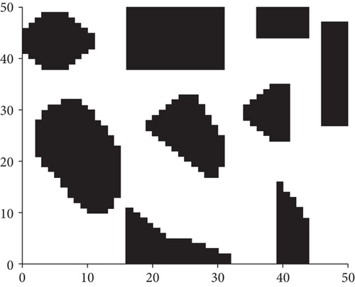
The main simulation environment consisted of an Intel (R) Core I i5-8265U CPU @1.60GHz, Windows10, and the simulations were conducted in MATLAB. A 50 km × 50 km path planning area and the corresponding grid map were established to verify the algorithm’s effectiveness. The UAV’s maximum turning angle was assumed to equal π/4. In the simulation, the grid granularity was set so that N = 1 km, the safety threshold equaled 0.8 km, and the UAV’s starting and ending coordinates were (0.5, 0.5) and (49.5, 49.5). The UAV’s flight environment is obtained by grid processing of arc obstacles and convex processing of concave obstacles. The UAV’s initial airspace is shown in Figure 9.
6.2. Simulation Studies on Path Planning with Known and Unknown Obstacles
6.2.1. Path Planning in the Initial Airspace Environment
The simulation experiment compared the improved A∗ algorithm, the standard DWA algorithm, and the fusion of A∗ and DWA algorithms to obtain the planning time and the resulting path’s length. The results are shown in Table 1.
| Algorithm | Path length (km) | Time (s) | Speed increase rate |
|---|---|---|---|
| Improved A∗ algorithm | 73.9423 | 0.2405 | |
| Standard DWA algorithm | 77.8257 | 3427.267 | 31.6% |
| Fusion of the improved A∗ and DWA algorithms | 75.6582 | 2531.638 |
The simulation results (Table 2 and Figure 10) demonstrate that the improved A∗ algorithm plans a globally optimal path. Compared with the improved A∗ algorithm, the path planned using the standard DWA algorithm is smoother but not globally optimal. Further, the planned path is not based on the planned global path, meaning there are several redundant paths. In Figure 10(c), the DWA algorithm combines the global path planning and considers the environmental information during the UAV’s flight. Consequently, the weight coefficient of the speed evaluation subfunction is adaptively adjusted, effectively reducing the UAV path planning time. Simultaneously, the obstacles are distinguished to reduce the impact of the known obstacles on the evaluation function, and the planned path is short and close to the global planning path.
| Algorithm | Path length (km) | Time (s) | Speed increase rate |
|---|---|---|---|
| Improved A∗ algorithm | 73.9423 | 0.2405 | |
| Standard DWA algorithm | 78.5025 | 3023.206 | 34.2% |
| Fusion of the improved A∗ and DWA algorithms | 76.5843 | 1942.824 |
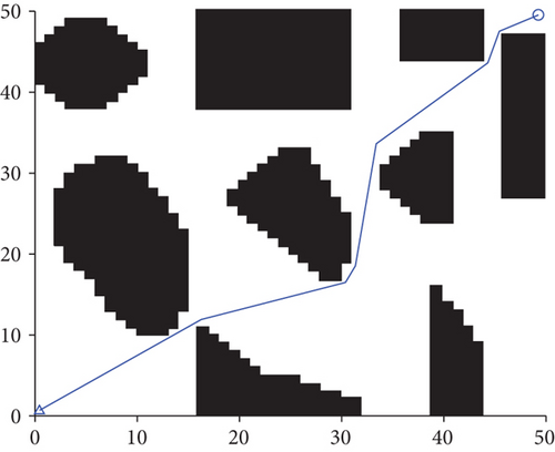
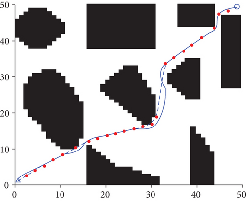
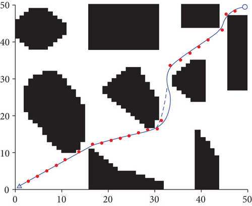
According to Table 1, the length of the path planned using the fusion of improved A∗ and DWA algorithm is reduced by 2.8% compared to that obtained via the standard DWA algorithm. Further, the planning time is reduced by 26.3%, and the average UAV’s flight speed is increased by 31.6%.
6.2.2. Path Planning When Obstacles Are Unknown
To verify the proposed algorithm’s path planning performance in an unknown environment, obstacles are temporarily set on the path planned by the UAV. The gray box represents the unknown obstacles (see Figure 11). As can be seen from Figure 11, the improved A∗ algorithm cannot yield a path avoiding the unknown obstacle. The standard DWA algorithm successfully avoids the obstacles, but the UAV only starts to bypass the obstacles when near them, enhancing the probability of a collision. In the case depicted in Figure 11(b), the UAV cannot fly along the initially planned global path, and there are many redundant paths, increasing the UAV’s flight distance. By combining the improved A∗ algorithm and DWA algorithm, the local path planning can be realized, and the unknown obstacles can be avoided effectively. The local path is similar to the global path, proving that a smooth and safe path can be obtained.

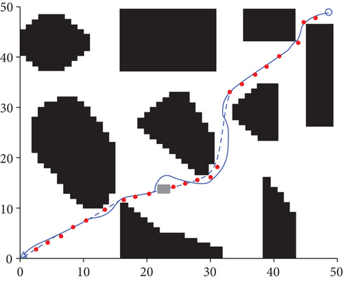
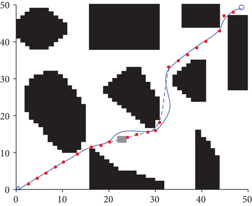
Similar to the experiment reported in Section 6.2.1, the simulation experiment compared the improved A∗ algorithm, the standard DWA algorithm, and the fusion of A∗ and DWA algorithms. The obtained path planning time and the path length are shown in Table 2.
As seen in Table 2, the improved A∗ and DWA algorithm reduces the planned path’s length by 2.4% compared with the standard DWA algorithm. Further, the planning time decreases by 35.7%, whereas the average UAV’s flight speed increases by 34.2%.
Next, environmental maps of different sizes were created to obtain environments of different complexity. The map ranges were set to 10∗10, 20∗20, 30∗30, 40∗40, and 50∗50. The shortest path length and path planning time under different environmental maps were extracted (Figures 12 and 13).
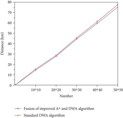
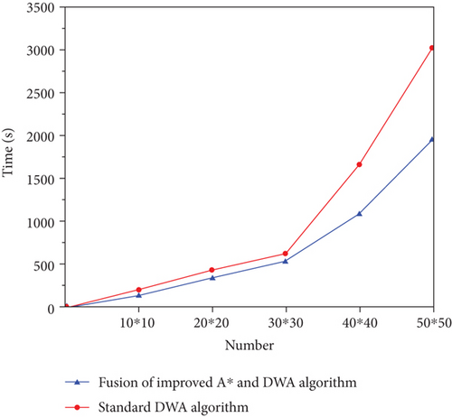
As shown in Figure 12, the increase in map size results in an increase in the UAV’s flight path. Compared with the standard DWA algorithm, the average path planned by the fusion of the improved A∗ and DWA algorithms is reduced by 4.22%. The advantages of the improved A∗ and DWA algorithm become more pronounced with the increase in map size. Figure 13 shows that the path planning time of the fused improved A∗ and DWA algorithms is significantly shorter than that of the standard DWA. In addition, the increase in map size highlights the advantages of the proposed improved A∗ and DWA algorithm, signaling that the algorithm is more conducive to the UAV’s path planning in a wide range.
7. Conclusion
- (1)
Through grid modeling of an irregular map, this work establishes grid processing of arc obstacles and convex processing of concave obstacles
- (2)
Environment information and motion constraints are utilized to improve the A∗ algorithm. When compared to the standard A∗ algorithm, the path planned by the improved A∗ algorithm is smoother, and the UAV’s motion safety is guaranteed
- (3)
An adaptive DWA is designed to dynamically adjust the path evaluation function using the safety threshold, UAV information, and environmental information regarding the obstacles
- (4)
The key nodes in the global path planned by the improved A∗ algorithm serve as the subtargets for the local path planning. Such a design ensures the optimal global path and improves the UAV’s real-time path planning efficiency and safety
- (5)
The experimental results show that the path planning based on the fusion of improved A∗ and DWA algorithms effectively reduces the path length, shortens the UAV’s path planning time, and improves both the path smoothness and the safety of the local obstacle avoidance
Conflicts of Interest
The authors declare that there is no conflict of interest regarding the publication of this paper.
Acknowledgments
The authors would like to thank the National Natural Science Foundation of China (Grant Nos. 51909245 and 51775518), the Open Fund of Key Laboratory of High Performance Ship Technology (Wuhan University of Technology), Ministry of Education (Grant No. gxnc19051802), the Natural Science Foundation of Shanxi Province (Grant No. 201901D211244), the High-Level Talents Scientific Research of North University of China in 2018 (Grant No. 304/11012305), the Scientific and Technological Innovation Programs of Higher Education Institutions in Shanxi (Grant Nos. 2020L0272 and 2019L0537), and the Natural Science Foundation of North University of China (Grant No. XJJ201908).
Open Research
Data Availability
The data used to support the findings of this study are available from the corresponding author upon request.


