Electromagnetic-Thermal Integration Design of Permanent Magnet Motor for Vehicles
Abstract
To more efficiently design high performance vehicular permanent magnet motor, an electromagnetic-thermal integration design method is presented, which considers both the electromagnetic properties and the temperature rise of motor winding when determining the main dimensional parameters of the motor. Then a 48-slot and 8-pole vehicular permanent magnet motor is designed with this method. The thermomagnetic coupling design is simulated and validated on the basis of multiphysical domain on finite element analysis. Then the prototype is analyzed and tested on a newly built motor experiment platform. It is shown that the simulation results and experimental results are consistent, which validate the accuracy and effectiveness of the new design method. Also this method is proved to well improve the efficiency of permanent magnet motor design.
1. Introduction
Vehicular permanent magnet motors are outstanding with high torque/current, high power density, high efficiency, and minitype light-weight. The urgent problems of motor design are how to reduce motor volume, save space, and improve material utilization rate while meeting specific performance indices. The design aims of vehicular permanent magnet motor should be high density, low weight, high reliability, high power at low-velocity, and constant-power wide-range speed control and to utmost increase the motor power density within limited space by enlarging the electromagnetic load. Thus, the size limit, electromagnetic load, and thermal load of vehicular motor are all far larger than common motor, and the temperature rise of motor becomes an extremely important indicator during vehicular permanent magnet motor design [1–3]. The traditional design methods of vehicular permanent magnet motor are to firstly design an electromagnetism scheme and thereby simulate temperature rise; the scheme is redesigned if the temperature rise is too high. This way is repeated until the electromagnetism scheme and motor temperature rise both are qualified. Admittedly, such design methods largely enlarge the workload of engineers and are less efficient. Thus, the electromagnetism design of vehicular permanent magnet motor should be integrated with the thermal design, forming an electromagnetic-thermal integration design (ETID) theoretical method for vehicular permanent magnet motor.
Currently, several methods for thermal analysis have been investigated in the literature. As reported, with a fluid-structure interaction finite element method (FEM), the steady-state temperature field of a 42 kW water-cooled vehicular permanent magnet synchronous motor under rated operating condition was simulated and analyzed [4]. A special cooling system and a new rotor structure prototype FEM model were built and were divided according to the heat production rate inside the motor and material properties [5]. A thermal magnetic coupling method for axial magnetic flux permanent magnet motor was proposed and used to segment the stators and rotors by using convection conduction analytical equations [6]. The thermal magnetic coupling of a double-salient-pole and double-rotor permanent magnet motor was analyzed by integrating thermal networks and FEM [7]. The lumped-parameter thermal network method and 3D fluid analysis were combined when the thermal effects of a surface-mounted permanent magnet motor with overhang structure were considered [8]. An electromagnetic-thermal-fluid integration analytical method was proposed for a permanent magnet synchronous motor [9]. A finite element package was used for the transient thermal analysis, under different load conditions and ambient temperatures, of a surface-mounted permanent magnet synchronous motor for aerospace actuation applications [10]. The thermal simulation model of in-wheel motor used for solar car was established, the thermal characteristics of in-wheel motor were analyzed by building the mass flow and heat-transfer coupling simulation model [11]. A new electrical-thermal two-way coupling design method was proposed to analyze the electromagnetic performances based on the investigated FSPM motor, where the change of PM material characteristics under different temperatures was taken into consideration [12]. A new Axial-Radial Flux-Type Permanent Magnet Synchronous Motor was presented. The performance of Axial-Radial Flux-Type Permanent Magnet Synchronous Motor (ARFTPMSM) can be adjusted by changing Axial Magnetic Motive Force (AMMF). The three-dimensional steady-state temperature field distributions of ARFTPMSM under different AMMF were investigated by using time-stepping FEM [13].
Simultaneously, several methods of motor design also have been investigated in the literature. The design processes in electromagnetic aspect of a high-speed solid cylindrical PM motor equipped with magnetic bearings were presented [14]. The design of the 4-kW 150-krpm ultra-high-speed SPMSM for an electrically assisted turbocharger was presented [15]. A novel surface-mounted outer rotor transverse flux permanent magnet motor with simple structure and good performance was proposed, which improved the motor performance by transforming parts of the leakage flux into the main flux [16]. The rotor shapes of IPM motors for electric vehicles were analyzed and five types of motor rotors for automobiles were analyzed, including two hybrid vehicles [17].
The above studies suggest the existence of many practical and feasible methods for motor thermal performance computation and electromagnetic design. However, the thermal performance simulation in all methods is conducted after the motor electromagnetic scheme is determined, and there is rare research on ETID. In this paper, based on the basic theories of traditional motor electromagnetic design and thermal design, we proposed an ETID method for motor design. The effectiveness and superiority of this method were validated by using a newly built 48-slot and 8-pole vehicular water-cooled permanent magnet motor.
2. Generalized Equations of ETID
2.1. Computation of Motor Main Dimensions
where Ki is the motor phase current waveform coefficient, KNM is the magnetic field waveform coefficient, Kdp is the winding factor, Dis is the motor stator inner diameter, lef is the effective stator core length, A is the line load, and Bδ is the peak value of air gap flux density.
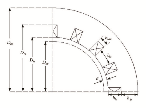
where Zs is the stator slot number.
2.2. Computation of Temperature
Rise in Stator Slots. During motor designing, generally the winding heat is the most nondissipatable, and usually the temperature rise of all other parts can be satisfactory as long as the temperature rise of winding is qualified.
where Th is the highest temperature and can be assigned with different empirical values according to the grade of insulation (e.g., A, B, F, H).
In sum, the major dimensional parameters of a motor not only relate to its electromagnetic performance, but also critically affect the temperature rise of motor winding.
3. Key Technical Flow Chart of ETID
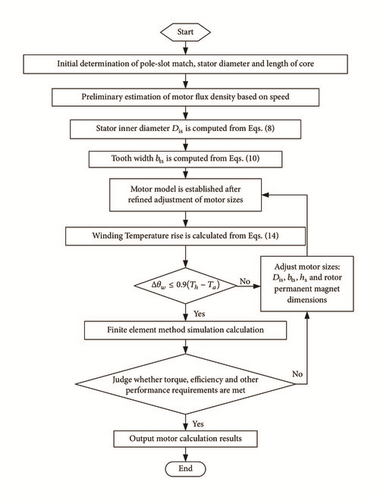
The key technical flowchart of the ETID is illustrated in Figure 2. Firstly, according to the design requirements, appropriate pole-slot match is selected; the motor stator outer diameter and motor iron core length are determined; the flux density is estimated according to the preset rotating speed; the stator inner diameter and tooth breadth are computed from (8) and (10); after refined adjustment, the shape of the stator slot is determined. Secondly, the motor winding temperature rise is calculated and judged according to (14) and (15); if the requirements of temperature rise are unsatisfied, the motor inner diameter Dis, tooth width bts, and slot height hs should be adjusted until the conditions are satisfied. Finally, an appropriate rotor magnetic steel structure is selected and a complete motor model is established for FEM computation; the electromagnetic torque, efficiency, and other performance indices of the motor are evaluated; if the design requirements are unsatisfied, the motor dimensions including rotor structure should be adjusted or refined until the design requirements are met.
4. ETID Simulation on FEM
According to the dimensional relation in Section 2.1, we set the outer diameter 230 mm as the baseline, pole-slot match = 48-slot and 8-pole, waveform coefficient KNm=1.11, phase current waveform coefficient Ki= 1.414, axial length lef =160mm, and rated rotating speed n=4000 rpm and thereby approximately estimated the electromagnetic density. The stator inner diameter Dis can be preliminarily estimated from (8). At the core stacking coefficient KFes =0.97 and Bδ =0.6T, we calculated the stator tooth width from (10).
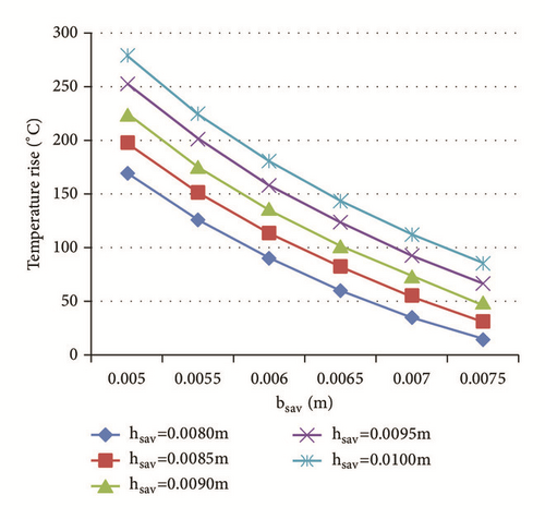
According to formulas (13) and (14), the curves of temperature rise in stator slot versus the equivalent height and width of stator slot are obtained as shown in Figure 3. It can be seen that the temperature rise in the stator slot is proportional to the equivalent height of the stator slot hsav and inversely proportional to the equivalent width of the slot bsav. Considering that the insulation level of the prototype winding is H and the ambient temperature is 48°C, the maximum temperature rise of the motor is estimated according to formula (15).
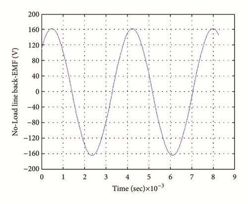
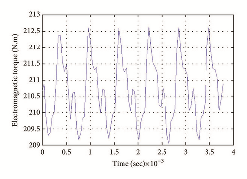
According to the above preliminary estimations, we designed a V-shaped rotor structure, appropriately refined the dimensional parameters, and designed the prototype machine with the performance and major dimensions showed in Table 1. The No-Load line back-EMF simulation waveform at 4000 r/min is illustrated in Figure 4, with the peak at 318 V. The electromagnetic torque simulation waveform at 4000r/min@88kW is showed in Figure 5, with the average electromagnetic torque 210.7 N•m.
| Parameters | Value |
|---|---|
| Rated power (kW) | 42 |
| Rated speed (rpm) | 4000 |
| Maximum power (kW) | 88 |
| Maximum speed (rpm) | 11500 |
| Stator outer diameter Dos (mm) | 230 |
| Stator inner diameter Dis (mm) | 156.4 |
| Rotor inner diameter (mm) | 43 |
| Pole/slot | 8/48 |
| Core length (mm) | 160 |
| Stator slot height hs (mm): | 20 |
| Tooth width bts (mm) | 6.54 |
| Air-gap length (mm) | 0.6 |
| Winding insulation level | H |
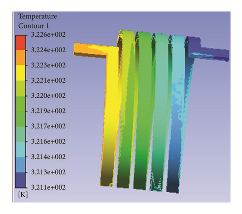
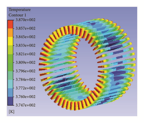
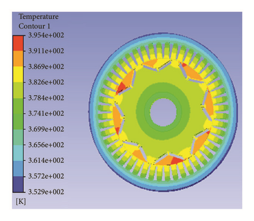
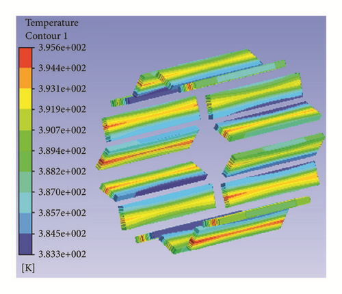
Given the multiphysical domain of circuit, electromagnetism, fluid, and temperature and based on the coupling simulation of control circuit, electromagnetic calculation, and thermal analysis, we determined the temperature distributions of key motor parts of the vehicular permanent magnet motor at working condition 4000r/min@42kW and considering inverter harmonic loss (Figure 6[3]). The highest temperatures of water jacket, stator winding, stator core, rotor core, and permanent magnet were 49.5°C, 113.8°C, 114.8°C, 122.2°C, and 122.4°C, respectively.
5. Experimental Verification
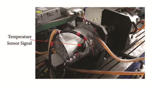
The test platform for prototype machine has been set up, as shown in Figure 7, in which two identical motors with the rated power 42kW are driven with each other. The tested motor adopts torque control while the other motor uses speed control. In addition, the cooling system is used in this experiment. With the purpose of monitoring temperature variation in each component, thermal resistors are, respectively, placed at the end winding of motor, the outer wall of frame, the underside of rotor permanent magnet, the water inlet, and the outlet of frame. The inlet water temperature is set for 48°C with the water flow rate 12L/min.
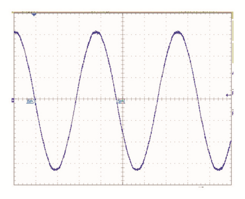
The No-Load line back-EMF measured waveform at 4000r/min was showed in Figure 8, with the peak value at 322 V. Clearly, the experimental data are very consistent with the simulation results in terms of waveform amplitude and shape.
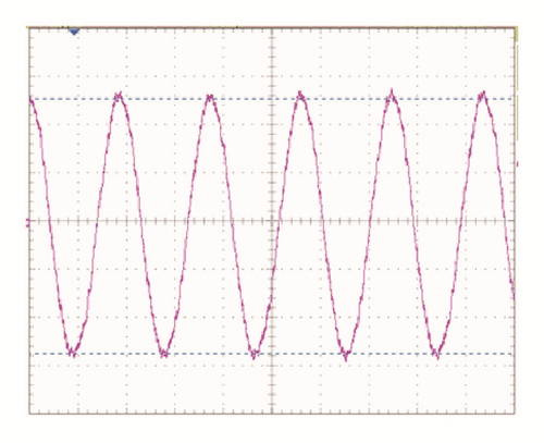
The current waveform experimentally measured at 4000r/min@88kW was showed in Figure 9. Since a current amplifier was used in the experiments, what the oscilloscope displayed was voltage signals. The voltage peak value was 1.064 V, and the current voltage change ratio was 1 A/mV. After conversion, the peak current of the input motor was 1064 A, or, namely, the current amplitude was 532 A, the current advance angle 37°, and motor output torque 210.6 Nm. The experimental results are very close to the simulation results.
The stator winding temperature and permanent magnet temperature measured at 4000r/min@42kW were 112°C and 123°C, respectively, which were very close to the simulated results (113.8°C, 122.4°C).
In all, the electromagnetic simulation results and thermal simulation results were very close to the experimentally measured results, indicating the vehicular permanent magnet motor ETID method proposed here was accurate and effective.
6. Conclusions
An efficient vehicular permanent magnet motor ETID method was proposed, which integrated both electromagnetism design and temperature rise design and thereby largely shortened the motor schematic designing period and enhanced the efficiency.
(1) During motor design, the key dimensional parameters affecting motor electromagnetic performance included stator inner diameter and tooth width, equations of which were presented here.
(2) Temperature rise of motor stator winding was a key indicator of motor thermal performance. Here the intraslot winding thermal conductive coefficient was equivalently computed, and thereby the winding temperature rise was estimated. Together with the empirical value range of winding temperature rise, the thermal design of motor winding was conducted, which was highly practical.
(3) A 48-slot and 8-pole permanent magnet motor with the rated power 42 KW was built for ETID. The experimental data were consistent with the simulated data. The motor ETID method was proved effective, accurate, and excellent and provides effective means for practical engineering applications.
Conflicts of Interest
The authors declare no conflicts of interest.
Acknowledgments
This work was supported by the National Natural Science Foundation of China under Grant no. 61572238 and the Shanghai Industry-University-Institute Cooperation Annual Plan Project under Grant no. Hu CXY-2015-014.
Open Research
Data Availability
The nature of the data is the motor size parameters; the data can be accessed from Electrical Machinery Laboratory of Shanghai University. The complete data belong to the joint ownership of the Electrical Machinery Laboratory of Shanghai University and the enterprise.


