Volume 2019, Issue 1 7026125
Research Article
Open Access

Nonlinear Dynamic Behavior of Winding Hoisting Rope under Head Sheave Axial Wobbles

Guoying Wang

Guoying Wang

School of Mechatronic Engineering, China University of Mining and Technology, Xuzhou 221116, China cumt.edu.cn

Search for more papers by this author
Xingming Xiao

Corresponding Author

Xingming Xiao

School of Mechatronic Engineering, China University of Mining and Technology, Xuzhou 221116, China cumt.edu.cn

Search for more papers by this author
Chi Ma

Chi Ma

School of Mechatronic Engineering, China University of Mining and Technology, Xuzhou 221116, China cumt.edu.cn

School of Information and Electrical Engineering, China University of Mining and Technology, Xuzhou 221116, China cumt.edu.cn

Search for more papers by this author
Gang Cheng

Gang Cheng

School of Mechatronic Engineering, China University of Mining and Technology, Xuzhou 221116, China cumt.edu.cn

Search for more papers by this author
Xiao Di

Xiao Di

School of Mechatronic Engineering, China University of Mining and Technology, Xuzhou 221116, China cumt.edu.cn

Search for more papers by this author
First published: 2019
Citations: 2
Academic Editor: Chao Tao

Abstract

Axial wobbles of the head sheave due to manufacturing accuracy and installation technology can exert periodic lateral excitations to the winding hoisting rope. A hoisting rope consists of a constant catenary rope from the drum to the head sheave and a variable vertical rope from the head sheave to the conveyance. The longitudinal and lateral vibration responses of the hoisting rope are coupled to each other. In this paper, the coupled lateral-longitudinal governing equations of the winding hoisting system under the axial wobble excitations of the head sheave are established by the Hamilton principle. The governing equations are nonlinear infinite-dimensional partial differential equations, which are discretized into the finite-dimensional ordinary differential equations through the Galerkin method. The dynamic responses of the hoisting rope under the head sheave axial wobbles are given by MATLAB simulation when the winding hoist is lifting or lowering. The results show that lateral vibration displacements of the vertical rope under the head sheave axial wobbles are larger than those of the catenary rope. The axial wobble amplitude range of the head sheave is given to limit the lateral vibration displacements of the hoisting rope.

1. Introduction

In order to increase production power, coal is being mined from strata at ever-increasing depths. The safety and reliability of the ultradeep mine hoist are becoming increasingly significant [1]. A hoisting rope of the winding hoist consists of a constant catenary rope from the drum to the head sheave and a time-varying vertical rope from the head sheave to the conveyance. The catenary rope and vertical rope are coupled at the head sheave. Manufacturing precision and installation process of the head sheave will subject it to periodic axial wobbles. They cause the hoisting rope to generate periodic lateral vibrations, which may be able to cause the rope to break. Therefore, there is a need to research lateral vibration responses of the winding hoist rope under axial wobbles of the head sheave.

The kinematics and dynamics of cables and strings have attracted interest of a large number of researchers [212]. The lateral vibration characteristics of axially moving strings are reviewed [13]. The dynamic responses of the string under a single motion force are given through the perturbation and numerical methods [2]. The dynamic behavior of the winch rope during winding or unwinding is given, which is verified with a new software toolbox [3]. The bending moment expression of the catenary rope is derived from the bending moment equation, and its large sag and bending stiffness are obtained [14]. Through the Galerkin method, the nonlinear dynamic characteristics of axially moving viscoelastic strings are given [4]. The steady-state periodic lateral behaviors of axially accelerating viscoelastic cables are given through the Hamilton principle and the Kelvin viscoelastic method [5]. The vibration behaviors of the rope with variable length and the lower-end additional mass-spring system are obtained by the multiscale method [6]. A spatial discretization method is given in order to predict dynamic characteristics of a time-varying rope system [7, 8]. The integrated model of the high-level building elevator is given. The research results show that nonlinear dynamic behaviors entering the various parts of a building elevator are mutually influential [9]. The nonlinear lateral vibration behaviors of the flexible elevator cable with variable length are given by the Hamilton principle [10]. The autoresonance characteristics of the lateral vibration of the elevator rope and the initial boundary value problem of lateral displacements due to boundary excitation are given [11, 12].

For dynamic behaviors of the hoisting rope in the coal mine hoisting system, some researchers conducted the following research. The lateral vibration responses of the incline cable and the longitudinal vibration responses of the vertical cable are researched through the Hamilton principle and the moving coordinate frame method [15, 16]. The dynamic behaviors of the winding hoist under flexible guides are studied based on the FDM. The influences of conveyance eccentricity and drum radius inconformity on the winding hoisting system are analyzed [17]. The vibration characteristics and control of the winding cable through crossover areas in the coal mine hoister are studied through the geometric method [18]. The lateral vibration characteristics of the catenary rope in the multirope friction hoisting system are researched and verified by experiment [19]. The dynamic characteristics of the mine hoisting ropes with variable length and roller guides with the diameter inconformity of drums are given by the Vd-FEM and Lagrange’s equations. The results show that the diameter inconformity of drums has a great influence on the tension deviation of the hoisting ropes [20]. The coupled longitudinal and torsional vibration equations of the multicable hoisting system in mine construction are derived through the constrained Lagrange equation. The results of numerical calculations are verified by Adams software [21].

From above literatures, few literatures have studied dynamic behaviors of the winding hoisting rope under the head sheave axial wobbles. Axial wobbles of the head sheave cause periodic lateral vibrations of the winding hoisting rope. The lateral and longitudinal vibrations of the winding hoisting rope are coupled to each other. Through the Hamilton principle, the coupled lateral-longitudinal governing equations of the winding hoisting rope under the axial wobbles of the head sheave are obtained. The governing equations are nonlinear infinite-dimensional partial differential equations, and the Galerkin method is applied to discretize the governing equations into finite-dimensional ordinary differential equations. The fourth-order Runge–Kutta method has been applied to work out ordinary differential equations. The numerical simulation and analysis are performed for the lateral vibration responses of the hoisting rope under the axial wobbles of the head sheave when the coal mine hoister is lifting or lowering.

The remainder of the paper is given as follows: In Section 2, the mathematical model of the winding hoisting system is obtained and discretized. In section 3, the numerical simulation and analysis are performed for the dynamic responses of the winding hoist rope under the axial wobbles of the head sheave. In section 4, the conclusions are given.

2. Mathematical Model of the Winding Hoisting System

2.1. Axial Wobbles of the Head Sheave

The axial wobble frequency of the head sheave is mainly the first three orders of periodic rotation frequencies [19]. In this paper, the first three orders of axial wobbles of the head sheave are used as the excitations for the lateral vibration of the hoisting rope. The excitation function of axial wobbles of the head sheave is
e m t = B m sin m γ t R s t , (1)
where Bm is the mth axial wobble amplitude of the head sheave (m = 1, 2, and 3), γ(t) is the working velocity of the winding hoist, t is the hoisting time of the hoist, and Rs is the radius of the head sheave.

2.2. Description of the Mathematical Model

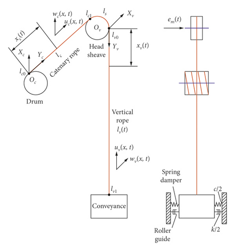
Multiple hoisting ropes are parallel to each other in the hoisting system. Thus, multiple hoisting ropes are considered to be a hoisting rope as the research object. The model of a winding hoisting system is shown in Figure 1. It includes a drum, a catenary rope, a head sheave, a vertical rope, a conveyance, spring dampers, and roller guides.
Details are in the caption following the image
Model of a winding hoisting system.

In this paper, two coordinates of the reference are established. The contact point between the drum and the catenary rope is the reference system OcXcYc. The contact point between the head sheave and the vertical rope is the reference system OvXvYv.

In this paper, lc0,  lc1,  lv0, and lv1 denote the contact point of the catenary rope and the winding drum, contact point of the catenary rope and the head sheave, contact point of the vertical rope and the head sheave, and contact point of the vertical rope and the conveyance, respectively; lc denotes the constant length of the catenary rope; lv(t) denotes the time-varying length of the vertical rope; u(x, t) and w(x, t) denote the longitudinal and lateral vibration displacements at x(t) of the hoisting rope, respectively; ρ is the linear density of the hoisting cable; g is the gravity acceleration; a is the working acceleration; E is Young’s modulus of the hoisting rope; A is the effective cross-sectional area of the hoisting rope; θ is the slope angle of the catenary rope; and mp is the hoisted mass per rope. The subscripts t, x, c, and v indicate the partial differential of t, the partial differential of x, catenary rope, and vertical rope, respectively.

The following assumptions are used to restrain the analysis: (1) The hoisting rope material is uniform. (2) The structure parameters of the hoisting rope remain invariant. (3) The slip of the hoisting rope is ignored. (4) The torsional and transverse out-of-plane vibration responses of the hoisting cable are ignored. (5) The elastic displacements due to longitudinal and lateral vibrations are greatly smaller than the length of the hoisting rope. (6) The effect of the air resistance is ignored.

The mathematical model of the winding hoisting system is obtained through the Hamilton principle. The motion of the system between t=t1 and t=t2 is
t 1 t 2 δ E k δ E p + δ W d t = 0 , (2)
where Ek, Ep, and δW denote the kinetic energy, potential energy, and virtual work of the winding hoisting system, respectively. For the sake of simplicity, u(x, t), w(x, t), lc(t), lv(t), em(t), x(t), a(t), and γ(t) indicate u, w, lc, lv, em, x, a, and γ, respectively.
Equation (2) can be solved through the variational principle and Leibniz’s rule. Therefore, the coupled lateral-longitudinal governing equations of the hoisting system are obtained as follows:
ρ Ω u + a T u , x E A Φ u , x = ρ g b , (3)
ρ Ω w T w , x W x + T w W x x E A Φ w , x W x + Φ w W x x = 0 , (4)
where Ωu and Ωw are the differential operator matrices of the longitudinal and lateral governing equations, respectively; Tu and Tw are the static tension matrices of the longitudinal and lateral governing equations, respectively; Φu and Φw are the strain matrices of the longitudinal and lateral governing equations, respectively; W is the matrix of lateral vibration displacements; a is the acceleration vector; and b is the column vector, respectively. These matrices and vectors are expressed as
T w = T c 0 0 T v , Φ w = ε c 0 0 ε v , Ω = Ω c Ω v T , T u = T c T v T , Φ u = ε c ε v T , W = w c w v T , a = a a T , b = 1 1 T . (5)

Equation (3) is the longitudinal governing equation of the hoisting rope in the winding hoisting system, and equation (4) is the lateral governing equation of the hoisting rope in the winding hoisting system.

The static tension of the hoisting rope is caused not only by the weight of the conveyance but also by its own weight. Therefore, the static tension of the hoisting rope can be expressed as
T c x , t = m p g + ρ l v l c x c sin θ g , T v x , t = m p g + ρ l v x v g , (6)
where Tc(x, t) is the static tension of the catenary rope and Tv(x, t) is the static tension of the vertical rope.
The differential operators Ωu and Ωw can be expressed as
Ω u = u t t + 2 γ u x t + a u x + γ 2 u x x , Ω w = w t t + 2 γ w x t + a w x + γ 2 w x x . (7)
According to Green’s symmetric strain tensor, the strain of the catenary rope and vertical rope can be expressed as
ε c = u c , x + 0.5 w c , x 2 , ε v = u v , x + 0.5 w v , x 2 . (8)
The initial boundary conditions of the winding hoisting system are given by
u c l c 0 , t = 0 , w c l c 0 , t = 0. (9)
The longitudinal and lateral boundary equations of the hoisting system at the head sheave are as follows:
J s R s 2 Ω u c 1 + a c s γ + u c 1 , t + E A ε v 0 ε c 1 = 0 , (10)
m p Ω w d E A Φ d W d , x m p g + c s γ W d , x c s W d , t = e m , (11)
where Js is the inertia moment and cs is the friction coefficient between the hoisting rope and the head sheave. The subscripts c1 and v0 indicate the lc1 point and lv0 point. These matrices can be expressed as
Φ d = ε c 1 0 0 ε v 0 , Ω w d = Ω c 1 Ω v 0 T , W d = w c 1 w v 0 T , e m = e m e m T . (12)
The longitudinal vibration displacements of the catenary rope are transmitted to the vertical rope at the head sheave. The longitudinal vibration displacement relationship between the catenary rope and the vertical rope can be obtained by
u v 0 = u c 1 e c s l s . (13)
The boundary equations of the hoisting system at the conveyance can be expressed as
m p Ω u v 1 + a + E A ε v 1 + ρ g l v 1 = 0 , (14)
m p Ω w v 1 + E A ε v 1 + T v 1 + c γ w v 1 , x + c w v 1 , t + k w v 1 = 0 , (15)
where k denotes spring stiffness of the roller guide and c denotes spring damping of the roller guide. The subscript v1 indicates the lv1 point.

Equations (14) and (15) are the longitudinal and lateral boundary equations of the hoisting system at the conveyance, respectively.

2.3. Discretization of the Mathematical Model

Lateral boundary equation of the hoisting system at the head sheave is in a nonhomogeneous form. It is necessary to change the nonhomogeneous equation to the homogeneous equation. Suppose the lateral vibration displacements of the hoisting system can be expressed as
w x , t = y x , t + e m 1 x l , (16)
where y(x, t) is the homogeneous equation. Inserting equation (16) into equations (4), (11), and (15), the coupled lateral-longitudinal infinite-dimensional nonlinear partial differential homogeneous equations of the hoisting rope are obtained, and then the Galerkin method is used to discretize them into the finite-dimensional ordinary differential equations.
To facilitate the analysis of the model, a dependent variable ψ = x/l is defined. A domain [0, l] with x is transformed into a domain [0, 1] with ψ. Longitudinal and lateral vibration displacements of the hoisting rope can be defined by
u ψ , t = i = 1 n ϕ i ψ q u , i t , y ψ , t = i = 1 n φ i ψ q w , i t , (17)
where n is the order of truncation. The fourth-order Galerkin truncation is available which enables to obtain precise numerical results [22], and thus, n = 4. qu,i(t) and qw,i(t) are longitudinal and lateral generalized coordinates, respectively. ϕi(ψ) and φi(ψ) are longitudinal and lateral trail functions, respectively, and they can be expressed as
ϕ i ψ = 2 sin 21 i 2 π ψ , i = 1,24 , , , φ i ψ = 2 sin i π ψ , i = 1,24. , , (18)
The longitudinal vibration equations are multiplied by ϕj(ψ) and the lateral vibration equations are multiplied by φj(ψ), and then the longitudinal and lateral vibration equations are integrated within ψ = [0, 1], respectively. The ordinary differential equations of the winding hoisting system can be obtained as
M Q t t + C Q t + KQ + P + F = 0 , (19)
where M, C, K, P, and F are the mass matrix, damping matrix, stiffness matrix, coupled matrix of the generalized coordinate, and generalized force matrix, respectively. These matrices are expressed as
M = M u c 0 0 0 0 M w c 0 0 0 0 M u v 0 0 0 0 M w v , C = C u c 0 0 0 0 C w c 0 0 0 0 C u v 0 0 0 0 C w v , K = K u c 0 0 0 0 K w c 0 0 0 0 K u v 0 0 0 0 K w v , P = P u c P w c P u v P w v T , F = F u c F w c F u v F w v T , Q = Q t , u c Q t , w c Q t , u v Q t , w v T , (20)
where Q t = q 1 t q 2 t q 4 t T is the generalized coordinate vector.

The specific expressions of the mass matrix, damping matrix, stiffness matrix, coupled matrix of the generalized coordinate, and generalized force matrix are in Appendix.

The ordinary differential equations of the winding hoisting system can be solved by the fourth-order Runge–Kutta method, and then generalized coordinates qwc,i(t) and qwv,i(t) are obtained. Combining (1), (16), and (17), the lateral vibration displacements of the catenary rope and the vertical rope can be obtained as
w c x , t = i = 1 4 φ i x c l c q w c , i t + B m sin m γ R s t 1 x c l c , w v x , t = i = 1 4 φ i x v l v q w v , i t + B m sin m γ R s t 1 x v l v . (21)

3. Numerical Simulations

The mathematical model can reflect the real dynamic behavior of the hoisting system under axial wobbles of the head sheave and is likely to analyze and conclude dynamic responses of the winding hoisting rope. Model parameters of the winding hoister applied for numerical simulations are shown in Table 1.

Table 1. Winding hoist parameters.
Parameters Value
Head sheave radius Rs (m) 2.5
Head sheave moment of inertia Js (kg/m2) 1.52 × 10⁴
Rope effective cross-sectional area A (m2) 1.9 × 10⁻³
Rope effective Young’s modulus E (N/m2) 1.1 × 10¹¹
Rope linear density ρ (kg/m) 8.53
Vertical rope maximum depth L0 (m) 1580
Catenary rope constant length lc (m) 80
Total hoisting times t (s) 120
Friction coefficient between hoisting rope and head sheave cs 0.5
Contact extent between hoisting rope and head sheave ls (m) 3.9
Angle between catenary rope and horizontal plane θ (rad) π/4
Hoisted mass per rope mp (kg) 5 × 10⁴
Gravity acceleration g (m/s2) 9.8
Roller guide spring stiffness k (N·m) 5.8 × 10⁵
Roller guide damping c (N·s/m) 8 × 10⁴

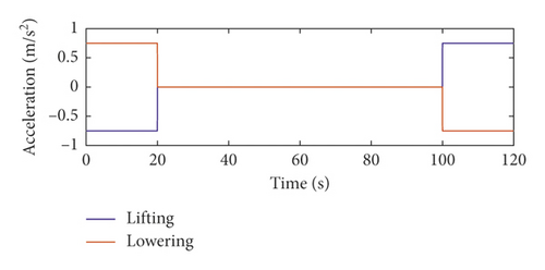
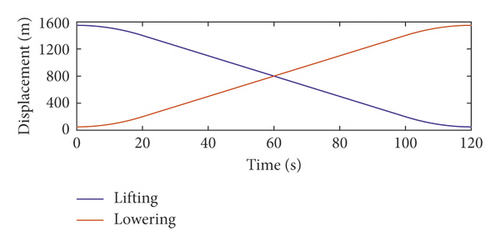
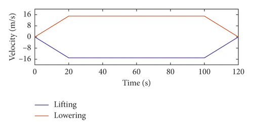
In this paper, the dynamic responses of the hoisting rope are analyzed when the winding hoist is lifting and lowering. The motion curves of the winding hoist are shown in Figure 2.
Details are in the caption following the image
Motion curves of the winding hoist.
Details are in the caption following the image
Motion curves of the winding hoist.
Details are in the caption following the image
Motion curves of the winding hoist.

The first-, second-, and third-order axial wobble amplitudes of the head sheave are 0.003 m, respectively. To ensure the safe operation of the mine hoist, it is assumed that the loads of the mine hoist in lifting and lowering are equal. According to the motion curves of the winding hoist, the lateral vibration displacements at the midpoint of the hoisting rope under the axial wobbles of the head sheave are given.

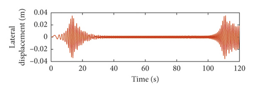
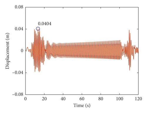
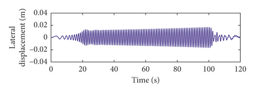
From Figures 3 and 4, it can be seen that the lateral vibration displacements of the catenary rope in lifting are similar to those in lowering. This is because the length of the catenary rope is constant. The excitation function is positively correlated with the axial wobble order of the head sheave. The larger the order of the head sheave axial wobbles, the closer the large amplitudes of the lateral vibration of the catenary rope to both ends.
Details are in the caption following the image
Lateral vibration displacements at lc/2 of the catenary rope in lifting. (a) The first-order excitation, (b) the second-order excitation, and (c) the third-order excitation of head sheave axial wobbles.
Details are in the caption following the image
Lateral vibration displacements at lc/2 of the catenary rope in lifting. (a) The first-order excitation, (b) the second-order excitation, and (c) the third-order excitation of head sheave axial wobbles.
Details are in the caption following the image
Lateral vibration displacements at lc/2 of the catenary rope in lifting. (a) The first-order excitation, (b) the second-order excitation, and (c) the third-order excitation of head sheave axial wobbles.
Details are in the caption following the image
Lateral vibration displacements at lc/2 of the catenary rope in lowering. (a) The first-order excitation, (b) the second-order excitation, and (c) the third-order excitation of head sheave axial wobbles.
Details are in the caption following the image
Lateral vibration displacements at lc/2 of the catenary rope in lowering. (a) The first-order excitation, (b) the second-order excitation, and (c) the third-order excitation of head sheave axial wobbles.
Details are in the caption following the image
Lateral vibration displacements at lc/2 of the catenary rope in lowering. (a) The first-order excitation, (b) the second-order excitation, and (c) the third-order excitation of head sheave axial wobbles.

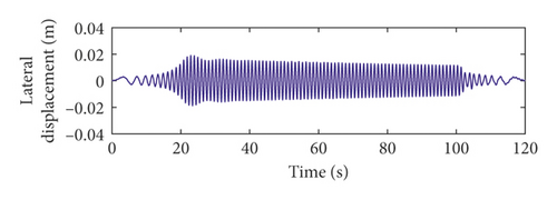
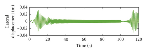
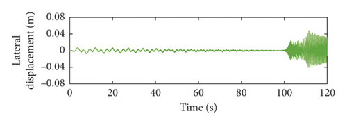
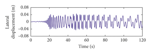
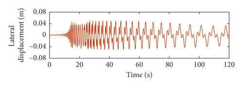
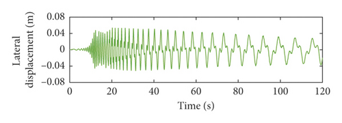
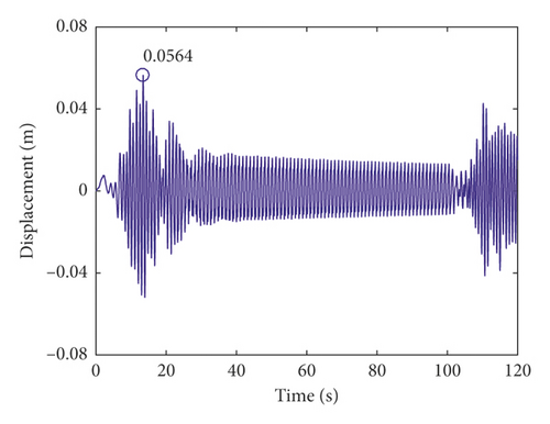
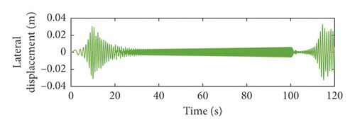
From Figures 5 and 6, it can be seen that the lateral vibration responses of the vertical rope in lifting are different from those in lowering. This is because the length of the vertical rope is variable. This verifies that it is required to research dynamic behaviors of the hoisting system during the lifting and lowering process. The larger the order of the head sheave axial wobbles, the closer the large amplitude of the lateral vibration of the vertical rope to the upper end of the well.

Details are in the caption following the image
Lateral vibration displacements at lv(t)/2 of the vertical rope in lifting. (a) The first-order excitation, (b) the second-order excitation, and (c) the third-order excitation of head sheave axial wobbles.
Details are in the caption following the image
Lateral vibration displacements at lv(t)/2 of the vertical rope in lifting. (a) The first-order excitation, (b) the second-order excitation, and (c) the third-order excitation of head sheave axial wobbles.
Details are in the caption following the image
Lateral vibration displacements at lv(t)/2 of the vertical rope in lifting. (a) The first-order excitation, (b) the second-order excitation, and (c) the third-order excitation of head sheave axial wobbles.
Details are in the caption following the image
Lateral vibration displacements at lv(t)/2 of the vertical rope in lowering. (a) The first-order excitation of head sheave axial wobbles. (b) The second-order excitation of head sheave axial wobbles. (c) The third-order excitation of head sheave axial wobbles.
This paper is to study the large displacement lateral vibration behaviors of the hoisting rope under the axial wobbles of the head sheave. Therefore, based on the safety and reliability the total lateral vibration displacements of the hoisting rope can be expressed as
w sum x , t = m = 1 3 w m x , t . (22)

The total lateral vibration displacements of the catenary rope under axial wobbles of the head sheave are shown in Figures 7 and 8. The lateral vibration responses of the catenary rope during the lifting process are substantially the same as those during the lowering process. Therefore, the total lateral vibration displacements of the catenary rope in lifting are not much different from those in lowering.

Details are in the caption following the image
Total lateral vibration displacements at lc/2 of the catenary rope in lifting.
Details are in the caption following the image
Total lateral vibration displacements at lc/2 of the catenary rope in lowering.

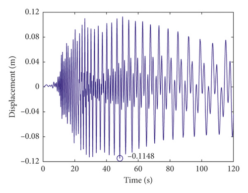
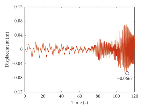
The total lateral vibration displacements of the vertical rope under axial wobbles of the head sheave are shown in Figures 9 and 10. The lateral vibration responses of the vertical rope during the lifting process are different from those during the lowering process. The total lateral vibration displacements of the vertical rope in lowering are about 1.7 times those in lifting. This is because the length of the vertical rope is variable with time. The length of the vertical rope is greater than that of the catenary rope. Thus, the total lateral vibration displacements of the vertical rope are larger than those of the catenary rope.

Details are in the caption following the image
Total lateral vibration displacements at lv(t)/2 of the vertical rope in lifting.
Details are in the caption following the image
Total lateral vibration displacements at lv(t)/2 of the vertical rope in lowering.

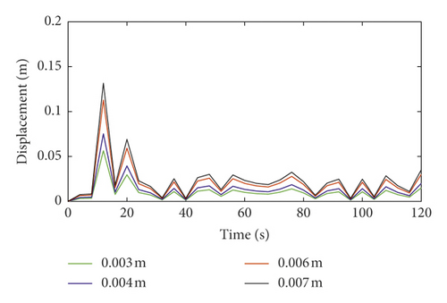
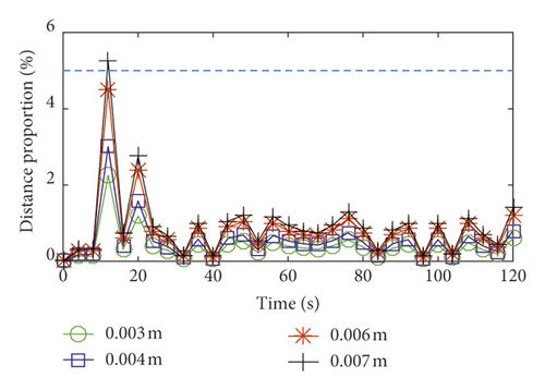
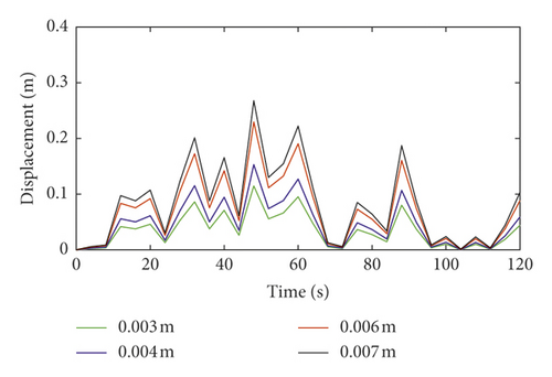
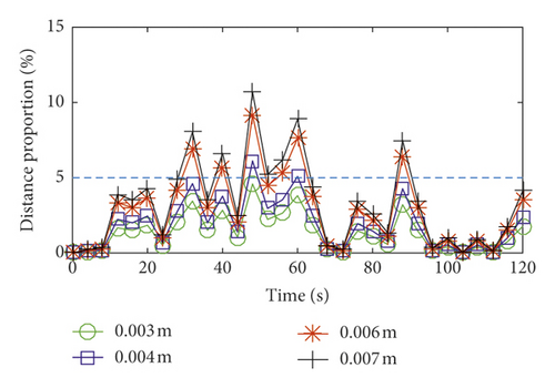
The total lateral vibration displacements and distance proportions of the hoisting rope under different axial wobble amplitudes of the head sheave are shown in Figures 11 and 12. The axial wobble amplitudes of the head sheave are positively correlated with the total lateral vibration displacements of the hoisting rope. This is the same as the actual operation of the coal mine hoist. Therefore, during the manufacture, design, and assembly of the head sheave, it is necessary to restrain axial wobble amplitudes of the head sheave in order to meet safety requirements of the coal mine hoist. According to the design requirements of the coal mine enterprise, the lateral vibration displacements should be constrained within the distance proportion 5% of the multirope winding hoist. Taking the same type and similar size of the double-rope winding hoist as an example, the distance between the two hoisting ropes is 5 m; when the axial wobble amplitude of the head sheave is less than 0.006 m, the distance proportion of the catenary rope is less than 5%. When the axial wobble amplitude of the head sheave is less than 0.003 m, the distance proportion of the vertical rope is less than 5%. Therefore, when the axial wobble amplitude of the head sheave is less than 0.003 m, it can meet the design requirements of the coal mine enterprise.

Details are in the caption following the image
Lateral vibration of the catenary rope under different axial wobble amplitudes of the head sheave. (a) Total lateral vibration displacements. (b) Distance proportions.
Details are in the caption following the image
Lateral vibration of the catenary rope under different axial wobble amplitudes of the head sheave. (a) Total lateral vibration displacements. (b) Distance proportions.
Details are in the caption following the image
Lateral vibration of the vertical rope under different axial wobble amplitudes of the head sheave. (a) Total lateral vibration displacements. (b) Distance proportions.
Details are in the caption following the image
Lateral vibration of the vertical rope under different axial wobble amplitudes of the head sheave. (a) Total lateral vibration displacements. (b) Distance proportions.

4. Conclusions

In this paper, the nonlinear vibration behavior of the hoisting rope under the axial wobbles of the head sheave in the coal mine winding hoist is studied. The mathematical model of the hoisting system is established by the Hamilton principle, and it can be solved by MATLAB simulation. The conclusions can be obtained as follows:
  • (1)

    The lateral vibration displacements of the catenary rope during lifting are substantially the same as those during lowering. The larger the order of the head sheave axial wobble, the closer the large amplitudes of the lateral vibration of the catenary rope to both ends. However, the lateral vibration displacements of the vertical rope during lifting are different from those during lowering. The larger the order of the head sheave axial wobble, the closer the large amplitude of the lateral vibration of the vertical rope to the upper end of the well.
  • (2)

    The total lateral vibration displacements of the catenary rope in lifting are slightly different from those in lowering. However, the total lateral vibration displacements of the vertical rope in lowering are larger than those in lifting. In addition, the total lateral vibration displacements under head sheave axial wobbles of the vertical rope are larger than those of the catenary rope.
  • (3)

    The axial wobble amplitude of the head sheave is positively correlated with the total lateral vibration displacement of the hoisting rope. As the same type and similar size of the double-rope coal mine winding hoist are used, when the axial wobble amplitude of the head sheave is less than 0.003 m, it meets the design requirement of the coal mine enterprise.

Conflicts of Interest

The authors declare that there are no conflicts of interest regarding the publication of this paper.

Acknowledgments

This work was partially supported by the National Natural Science Foundation of China (51675520) and the project funded by the Priority Academic Program Development of Jiangsu Higher Education Institutions (PAPD).

    Appendix

    The matrices of mass, damping, stiffness, coupled term of the generalized coordinate, and generalized force are as follows:
    M u c , i j = ρ δ i j + J s l c R s 2 ϕ c , i 1 ϕ c , j 1 , M w c , i j = ρ δ i j + J s l c R s 2 ϕ c , i 1 ϕ c , j 1 , M u v , i j = ρ δ i j + m p l v ϕ v , i 1 ϕ v , j 1 , M w v , i j = ρ δ i j + m p l v φ v , i 1 φ v , j 1 , C u c , i j = 2 ρ γ l c 0 1 ϕ c ψ , i ϕ c , j d ψ c c s l c ϕ c , i 1 ϕ c , j 1 , C w c , i j = 2 ρ γ l c 0 1 φ c ψ , i φ c , j d ψ c , C u v , i j = 2 ρ γ l v 0 1 1 ψ v ϕ v ψ , i ϕ v , j d ψ v , C w v , i j = 2 ρ γ l v 0 1 1 ψ v φ v ψ , i φ v , j d ψ v + c l v φ v , i 1 φ v , j 1 , K u c , i j = ρ a l c 0 1 ϕ c ψ , i ϕ c , j d ψ c + ρ γ 2 E A l c 2 0 1 ϕ c ψ ψ , i ϕ c , j d ψ c , K w c , i j = ρ a ρ g sin θ l c 0 1 φ c ψ , i φ c , j d ψ c + ρ g sin θ l c 0 1 ψ c φ c , ψ ψ i φ c , j d ψ c + ρ γ 2 m p + ρ l v g l c 2 0 1 φ c ψ ψ , i φ c , j d ψ c 3 e m 2 E A 2 l c 4 0 1 φ c ψ ψ , i φ c , j d ψ c , K u v , i j = ρ a l v 0 1 1 ψ v ϕ v ψ , i ϕ v , j d ψ v + ρ γ 2 l v 2 0 1 1 ψ v 2 ϕ v ψ ψ , i ϕ v , j d ψ v E A l v 2 0 1 ϕ v ψ ψ , i ϕ v , j d ψ v + E A l v 2 1 e c s l s ϕ c ψ , i 1 ϕ c , j 1 , K w v , i j = ρ a l v 0 1 1 ψ v φ v ψ , i φ v , j d ψ v + ρ γ 2 l v 2 0 1 1 ψ v 2 φ v ψ ψ , i φ v , j d ψ v ρ g l v 0 1 1 ψ v φ v ψ ψ , i φ v , j d ψ v m p g l v 2 + 3 e m 2 E A 2 l v 4 0 1 φ v ψ ψ , i φ v , j d ψ v + k l v φ v , i 1 φ v , j 1 , P u c , i j = e m E A l c 3 0 1 i = 1 4 q w c , i φ c ψ ψ , i ϕ c , j d ψ c E A 2 l c 3 0 1 i = 1 4 q w c , i φ c ψ , i i = 1 4 q w c , i φ c ψ ψ , i ϕ c , j d ψ c , P w c , i j = E A l c 3 0 1 i = 1 4 ϕ u ψ , i q u c , i i = 1 4 φ c ψ ψ , i q w c , i φ c , j d ψ c + e m E A l c 3 0 1 i = 1 4 ϕ c ψ ψ , i q u c , i φ c , j d ψ c + 3 e m E A l c 4 0 1 i = 1 4 φ c ψ , i q w c , i i = 1 4 φ c ψ ψ , i q w c , i φ c , j d ψ c E A l c 3 0 1 i = 1 4 ϕ u ψ ψ , i q u c , i i = 1 4 φ c ψ , i q w c , i φ c , j d ψ c 3 E A 2 l c 4 0 1 i = 1 4 φ c ψ , i q w c , i 2 i = 1 4 φ c ψ ψ , i q w c , i φ c , j d ψ c , P u v , i j = e m E A l v 3 0 1 i = 1 4 ϕ v ψ ψ , i q u v , i ϕ v , j d ψ v E A 2 l v 3 0 1 i = 1 4 ϕ v ψ , i q u v , i 2 ϕ v , j d ψ v + 1 e c s l s i = 0 4 q c , i t ϕ c ψ ψ , i 1 ϕ c , j 1 , P w v , i j = E A l v 3 0 1 i = 1 4 ϕ v ψ , i q u v , i i = 1 4 φ v ψ ψ , i q w v , i φ v , j d ψ v E A l v 3 0 1 i = 1 4 ϕ v ψ ψ , i q u v , i i = 1 4 φ v ψ , i q w v , i φ v , j d ψ v 3 E A 2 l v 4 0 1 i = 1 4 φ v ψ , i q w v , i 2 i = 1 4 φ v ψ ψ , i q w v , i φ v , j d ψ v + E A e m l v 3 0 1 i = 1 4 ϕ v ψ , i q u v , i φ v , j d ψ v + 3 E A e m l v 4 0 1 i = 1 4 φ v ψ , i q w v , i i = 1 4 φ v ψ , i q w v , i φ v , j d ψ v , F u c , i j = ρ a g 1 + sin θ 0 1 ϕ c , j d ψ c + J s a R s 2 l c ϕ c , j 1 , F w c , i j = ρ e m , t t + ρ g sin θ ρ a e m 2 ρ γ e m , t l c 0 1 φ c , j d ψ c ρ e m , t t 0 1 ψ c φ c , j d ψ c , F u v , i j = ρ a 0 1 ϕ v , j d ψ v + m p a 2 l v + E A e m 2 2 l v 3 ϕ v , j 1 , F w v , i j = ρ e m , t t 2 ρ γ e m , t + ρ a e m l v + 2 ρ γ 2 e m l v 2 0 1 1 ψ v φ v , j d ψ v + ρ g e m l v 0 1 1 ψ v φ v ψ ψ , j d ψ v + m p g e m l v 2 + E A e m 3 2 l v 4 0 1 φ v ψ ψ , j d ψ v , (A.1)
    where δij is the Kronecker delta and is defined as
    δ i j = 1 , i = j , δ i j = 0 , i j , i = 1,241,24. , , j = , (A.2)

    Data Availability

    The data used to support the findings of this study are available from the corresponding author upon request.

      The full text of this article hosted at iucr.org is unavailable due to technical difficulties.