Suboptimal Midcourse Guidance with Terminal-Angle Constraint for Hypersonic Target Interception
Abstract
For the problem of hypersonic target interception, a novel midcourse guidance method with terminal-angle constraint is proposed. Referring to the air-breathing and the boost-gliding hypersonic targets, flight characteristics and difficulties of interception are analyzed, respectively. The requirements of midcourse guidance for interceptors are provided additionally. The kinematics model of adversaries is established concerning line-of-sight coupling in longitudinal and lateral planes. Suboptimal guidance law with terminal-angle constraint, specifically the final line-of-sight angle or impact angle, is presented by means of model predictive static programming. The trajectory is optimized and the load factor would finally converge after penalizing control sequence and output deviations. The realization of terminal angle is firstly verified with a constant speed target. A full interception scenario is further simulated focusing on a typical boost-gliding target, which flies along a skipping trajectory. Results show the success of providing handover conditions for intercepting hypersonic targets.
1. Introduction
The hypersonic vehicle, typically traveling greater than Mach 5 in the near space, has developed rapidly in recent years, and their weaponization has accelerated. Compared with conventional missiles, hypersonic weapons show great advantages of diverse launching platforms, fast flight speed, and strong penetration capability. Aiming at time-sensitive and high-value targets, they pose severe challenges to the traditional antiaircraft or antimissile defense system. Hypersonic vehicles are going through intensive flight testing, for instance, the “Hypersonic Air-breathing Weapon Concept” and “Tactical Boost Glide” [1], the Russian “Zircon” hypersonic cruise missile [2], and the Chinese “DF-ZF” hypersonic glide vehicle [3, 4]. The defense system should be upgraded and prepared to meet the requirements of the future battlefield.
In order to eliminate the target in time, modern interceptors generally require the ability of beyond-visual-range air combat. Midcourse guidance is vital to the entire interception process. The purpose is to lead the interceptor to a desired position, where not only the target can be acquired but also a good initial angle is obtained for the terminal phase, thus to increase the interception rate. Midcourse guidances for intercepting conventional aviation targets or ballistic missiles are relatively mature. For example, concerning air-to-air missile, singular perturbation theory was applied to the derivation of near-optimal midcourse guidance in articles [5–7], but they did not consider the angle alignment constraints. Focusing on the optimal guidance problem with angular constraint, Indig et al. [8] proposed an analytic guidance law with a linear dynamic model, which would cause control saturation at the time of interception. Liu et al. [9] designed a biased proportional navigation guidance method with attitude constraint and line-of-sight angle rate control, but it mainly aimed at stationary ground target, not to mention the capability of energy management. Taking constant acceleration into consideration, Seo and Tahk [10] provided a closed-loop midcourse guidance law, but the terminal constraint can be fulfilled only under the assumption that the impact point was precisely predicted. To maximize the kill probability, Phillips and Drake [11] designed a two-tier approach for surface-to-air midcourse trajectory with an auxiliary constraint on an intersection approach angle. Three classes of midcourse guidance laws, namely, optimal fuel, optimal energy, and closed-loop explicit strategy, are proposed by Jalali-Naini and Pourtakdoust [12] with a zero-effort miss differential equation. Selecting different objectives and constraint functions, Reza and Abolghasem [13] solved an optimal interception problem with receding horizon control; commands are generated online by means of a differential flatness concept and nonlinear programming. Characterized by ultrafast speed and large-scale maneuverability, the requirements for hypersonic target interception become extremely strict, thus failing most of the existing midcourse guidance methods. New approaches must be found for these special targets, which can not only optimize trajectory online but also satisfy terminal-angle constraint.
To solve the real-time suboptimal problem with terminal constraints, Dwivedi et al. [14, 15] and Padhi and Kothari [16] put forward the model predictive static programming (MPSP) technique, which combines the “model predictive control” and “approximate dynamic programming” philosophies. With the qualities of accurate convergence and low computational cost, the MPSP technique has attracted extensive attention. Applying the MPSP algorithm, Oza and Padhi [17] presented a guidance law for air-to-ground missiles, which satisfies the constraint of terminal impact angle; superiority was demonstrated in comparison with augmented proportional navigation guidance and explicit linear optimal guidance. Halbe et al. [18] presented a robust suboptimal reentry guidance scheme for a reusable launch vehicle with the help of the MPSP algorithm. Apart from hard constraints of terminal conditions, soft constraints on path and control were also introduced through an innovative cost function, which consists of several components with various weighting factors. To solve the state variable inequality constraint, Bhitre and Padhi [19] converted the MPSP problem into an unconstrained but higher dimension one by means of a slack variable technique. Afterwards, the state constrained MPSP formulation was tested on an air-to-air engagement scenario. Considering the soft landing problem of a lunar craft during the powered descent phase, Sachan and Padhi [20] proposed a fuel optimal guidance law under the help of G-MPSP, where both terminal position and velocity were satisfied by adjusting the magnitude and angle of thrust. Bringing in sliding mode control, S. Li and X. Li [21] solved the divergence problem of the common MPSP algorithm caused by model inaccuracy; better robustness was proved when applied to maneuvering target interception. Moreover, Maity et al. [22, 23], Kumar et al. [24], and Guo et al. [25] also promoted the MPSP theory and applied it to the guidance design.
These aforementioned MPSP guidance laws in [15, 17] only lead the vehicle to a desired position defined by Y(X) and Z(X). However, when referring to a defense scenario, the optimal handover point changes with the maneuvering target, which requires additional prediction in every guidance cycle. In the process of midcourse guidance design for three-dimensional interception, the line-of-sight is not considered, which is vital to the flight trajectory and the startup of detection system. In addition, state-of-the-art guidance methods for intercepting hypersonic speed and large-scale maneuverable target are rarely researched to the best of the authors’ knowledge. To solve these problems, this paper adopts the line-of-sight coupled interception model and proposes a novel midcourse guidance method with the MPSP technique according to the characteristics of a specific target, which can optimize the interceptor’s trajectory and also meet the handover constraints.
The rest paper is organized as follows. In Section 2, the characteristics and technical requirements of midcourse guidance for hypersonic target interception are analyzed, and a three-dimensional interception model is established. In Section 3, suboptimal guidance law with constrained terminal line-of-sight or impact angle is derived utilizing the MPSP approach. The guidance scheme is validated in Section 4, considering a constant speed target and a typical boost-gliding target. Finally, the text is briefly summarized in Section 5.
2. Midcourse Guidance Problem
2.1. Consideration for Hypersonic Interceptor
- (1)
Different from most ballistic missiles, hypersonic target can perform a wide range of maneuver strategies without affecting the final attack performance during the strike mission, which raises the demand of accuracy and timeliness for target tracking and prediction
- (2)
Limited by the working condition of structure and detection system, the interceptor’s speed is generally slower than that of the target’s. Therefore, head-on or head pursuit guidance [26, 27] remains the only choice
- (3)
In view of the high closing speed and the capability of penetration, the velocity heading error must be small enough at the beginning of the terminal phase. Head-on condition is beneficial for a successful interception
- (4)
As the hypersonic target flies in a large airspace and midcourse guidance takes a relatively long time, the abilities of rapid trajectory correction and flight energy management become essential for the interceptor
Hypersonic vehicles are mainly classified into two categories, the air-breathing type equipped with scramjet engine like the X-51 and the boost-gliding type powered by rockets like the HTV-2 [28]. Significant differences can be found in their maneuvering strategy and capability. The air-breathing hypersonic target is critically restricted by the operation conditions of the scramjet. It generally adopts horizontal flight in the longitudinal plane during cruise segment, while bank-to-turn control is applied in the lateral plane to achieve evasive maneuvers. Being absent of thrust after reentry, the boost-gliding target however employs skip ballistic to increase flight distance; bank angle is adjusted to ensure the heading direction. Target identification can be done with the help of early warning systems. Midcourse guidance is then designed, respectively, according to the differences between air-breathing and boost-gliding hypersonic targets.
- (1)
To make use of the “zero-effort miss” concept, the line-of-sight rate had better approach zero at the handover of the midcourse phase and terminal phase. So long as the target does not maneuver, the interceptor will strike on the target without extra control. In other words, the load factor of the interceptor tends to zero, which is beneficial to the separation from the booster and the overload reservation for compensating target perturbations
- (2)
To satisfy the capture conditions of the on-board seeker and improve the success rate of final interception, it is important to meet the limit of the final line-of-sight angle or impact angle. The optimal interception geometry will be obtained if an approximate head-on scenario is realized
- (3)
Considering the trajectory smoothness and energy constraint, the control command for the interceptor should be optimized
- (4)
For the target implementing a large maneuver, its flight path angle or velocity azimuth angle changes frequently; midcourse guidance with velocity angle alignment for the interceptor becomes overreacting and guidance performance will suffer. In such circumstances, line-of-sight constrained midcourse guidance is preferred to realize the optimal aspect angle. Otherwise, guidance laws with a velocity angle constraint will be better if the target employs a small maneuver. In this way, the optimized impact angle can be achieved [29], thus reducing the overload demand for the terminal phase
2.2. Coupled Line-of-Sight Dynamics
The kinematic relationship between the pursuer and evader in a three-dimensional space is shown in Figure 1, where M and T are centroids of the interceptor and target, respectively. MX1Y1Z1 is the line-of-sight coordinate system. The axis MX1 is aligned with the line-of-sight and points to target T. Staying in a vertical plane, the axis MY1 is normal to MX1 and points upward. The axis MZ1 is defined by the right-hand rule and is normal to MX1 and MY1. AXYZ is the inertial reference coordinate system, and for clarity of illustration, its origin A is translated to coincide with the origin M. Hereafter, two Euler angles are introduced [30]. qε stands for the elevation line-of-sight, namely, the angle between the line-of-sight and horizontal plane ZAX. qβ is the azimuth line-of-sight, which acts on the horizontal plane with respect to reference direction AX. R represents the relative distance between the interceptor and target.
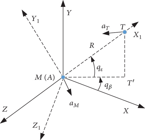
Generally, the thrust magnitude of the interceptor is designed previously according to the velocity characteristics, and the drag on the vehicle is closely related to its dynamic pressure. As a consequence, the term aMR is difficult to be controlled during flight. In fact, like proportional navigation (PN) and most other guidance laws do, the control of aMR is not necessary as long as . Thereby, the equation along the MX1 direction can be ignored.
The objective in the midcourse guidance design is to optimize the control history of aMε and aMβ, meanwhile satisfying the constraints in the guidance process and at the handover.
3. Angle Constrained MPSP Guidance
In this section, the suboptimal midcourse guidance law with a terminal-angle constraint is derived by means of the MPSP algorithm, in particular, the line-of-sight constrained MPSP guidance and the impact angle constrained MPSP guidance.
3.1. Line-of-Sight Constrained Guidance
A brief principle of MPSP can be described as follows. Firstly, expand the observed output with first-order Taylor series at the expected terminal point. Then, the deviation between the predicted output and the desired value can be formulated by an initial state error and control error history. Applying an appropriate cost function, the corrected control is derived from iterative calculation, when the final output value approximates the expected one.
- (1)
Different from the terminal phase, midcourse guidance lasts longer. The hypersonic target is most likely to adopt various maneuver strategies, causing the changes of its acceleration at all times. It is not reliable to predict the future maneuvers of the hypersonic target. Therefore, the acceleration is neglected briefly
- (2)
Applying the quasisteady assumption, the closing velocity of the adversaries is regarded as a constant, namely, . Guidance law acts periodically, the closing velocity is updated in every guidance cycle, and the deviations would be corrected
Now, the measured output is selected in terms of specific guidance requirements, right in the state of the system, and we get Yk = Xk. Marking N as the prediction horizon of the MPSP method, the missile-target range step is expressed as Rstep = (Rinit − Rend)/(N − 1), where Rinit indicates the missile-target distance at every guidance epoch and Rend means the handover distance. Then, the increment of time is obtained by T = Rstep/Vc.
In conclusion, the line-of-sight constrained MPSP guidance is numerically solved by the control (25), considering the discrete guidance problem (8) with the required output (11) and cost function (22). Note that the control sequence Uk(k = 1, 2, …, N − 1) is solved in each guidance period, but only U1 is employed as the current guidance command. The suboptimal midcourse guidance law for target interception not only optimizes the flight control but also satisfies the terminal constraints of the line-of-sight angle and its rate.
3.2. Impact Angle Constrained Guidance
As already mentioned in Section 2.1, the midcourse guidance with velocity angle alignment exhibits better handover properties if the target’s maneuver is somehow weak. However, only the line of sight and line-of-sight rate are involved while modeling the interception scenario. A solution can be found in [31], where the desired impact angle is able to be transferred into the final line-of-sight angle. For simplicity, the following process is done in the longitudinal plane and the lateral plane is similar.
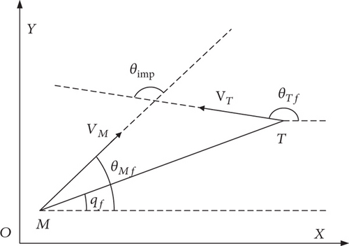
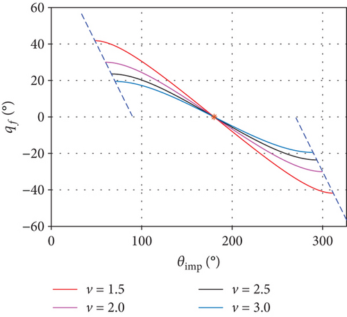
Different from the situation in [31], the interceptor no longer has velocity advantage, namely, v > 1; the singular problem is structurally avoided. One-to-one condition of qf and θimp is further analyzed, in which a monotonous zone including head-on condition can be found. Considering an incoming target with θTf = π, the relationship between qf and θimp changes according to the speed ratio v, as shown in Figure 2(b). Since qf is continuous, extreme points can be obtained by driving dqf/dθimp = 0, which gives vcosθimp = 1. In conclusion, for any desired impact angle θimp ∈ (arccos(1/v), 2π − arccos(1/v)), a corresponding qf can be calculated by (29).
Applying (29), the aforementioned line-of-sight constrained MPSP guidance is transferred into the impact angle constrained MPSP guidance, which actually constrains the final flight path angle for the interceptor in the midcourse phase. Note that the prediction of the target’s terminal flight path angle is required.
4. Simulation
Three different scenarios are presented to validate the effectiveness of the constrained MPSP midcourse guidance law. The first two scenarios refer to the cruising hypersonic target with a constant velocity in the longitudinal plane. Line-of-sight constrained and impact angle constrained midcourse guidance are applied, respectively; The last scenario considers the gliding target with a skipping trajectory in a three-dimensional space, and a full guidance scheme including midcourse is adopted.
4.1. Problem Setup
4.1.1. Interceptor and Target Model
4.1.2. Overall Guidance Scheme
The proposed terminal-angle constrained MPSP guidance law is applied for interceptor’s midcourse flight. This approach requires the line-of-sight and line-of-sight rate information in real time. However, on-board detection system will not be activated until the capture conditions are satisfied. Assuming that the interceptor can receive target’s information provided by ground radar or space-based infrared system, additional filter and prediction are necessary for signal extraction and denoising. For those air-breathing hypersonic targets, the interacting multiple model algorithm with commonly “CA” and “current” statistical models is preferred accounting for its complex maneuverability. However, it is reported in the literature that filter based on the nonlinear Markov acceleration model [34] exhibits better performance for boost-gliding targets.
4.2. Line-of-Sight Constrained Guidance
- (1)
The initial position of the interceptor 0,17 km, the average velocity at 1200 m/s, 0° initial flight path angle, and 5 g maximum overload
- (2)
The initial position of hypersonic target 400,35 km, the average velocity at 2400 m/s, 180.286° initial flight path angle, and without maneuver
- (3)
Terminal handover distance is 60 km, simulation step of 20 ms, and the scheduled final line-of-sights are -5°, 0°, and 5°, respectively
- (4)
Initial control guess utilizes the three-dimensional proportional guidance law
The results are shown in Table 1 and Figure 3.
| R(m) | qf( °) | nyf(g) | |||
|---|---|---|---|---|---|
| qf = −5° | Default | 60000 | -5 | 0 | -0.149 |
| Real | 59960 | -5.000 | −5.908e − 5 | ||
| qf = 0° | Default | 60000 | 0 | 0 | -0.052 |
| Real | 59972 | −8.377e − 6 | −1.800e − 5 | ||
| qf = 5° | Default | 60000 | 5 | 0 | -0.057 |
| Real | 59940 | 5.000 | −2.21e − 6 |
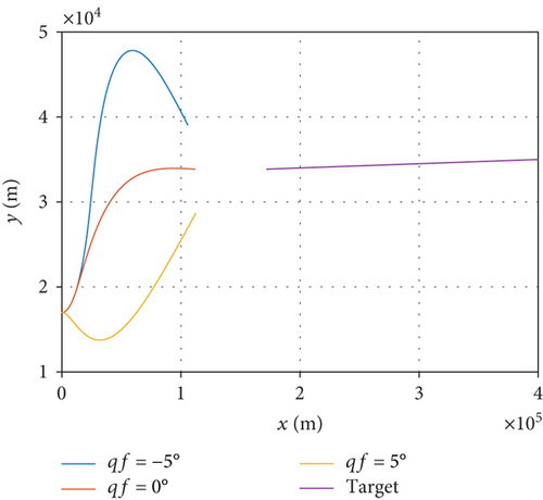
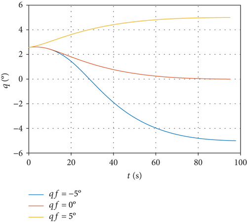
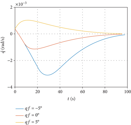
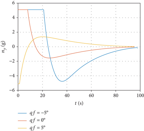
From Figure 3(a), we can see that the interceptor is able to reach the desired position under the command of the line-of-sight constrained MPSP guidance algorithm, right in the front of the hypersonic target. Figures 3(a) and 3(b) indicate that the terminal constraints of both line-of-sight and line-of-sight rate have been satisfied with high accuracy. In Figure 3(d), the overload command can gradually converge to zero, thus providing a favorable initial condition for the endgame interception.
4.3. Impact Angle Constrained Guidance
To validate the impact angle constrained MPSP midcourse guidance, the same simulation conditions are set as in Section 4.2, except that the required impact angles are 170°, 180°, and 190°, where 180° represents a typical head-on collision. The simulation results are shown in Table 2 and Figure 4.
| R(m) | θimp( °) | nyf(g) | |||
|---|---|---|---|---|---|
| θimp = 170° | Default | 60000 | 0 | 170 | 0.015 |
| Real | 59981 | 5.614e − 6 | 170.016 | ||
| θimp = 180° | Default | 60000 | 0 | 180 | -0.051 |
| Real | 59959 | −1.465e − 5 | 179.958 | ||
| θimp = 190° | Default | 60000 | 0 | 190 | -0.104 |
| Real | 59945 | −2.948e − 5 | 189.915 |
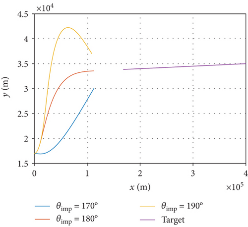
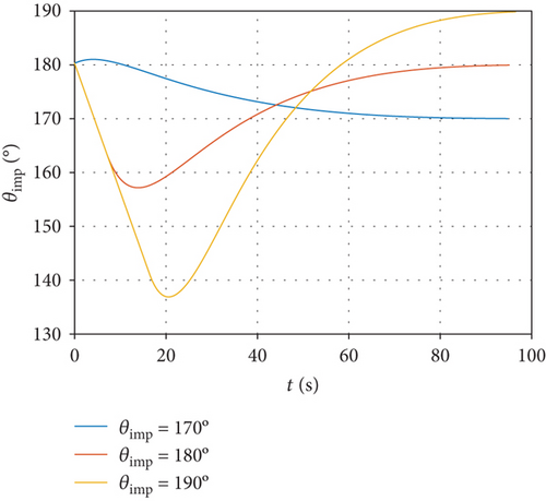
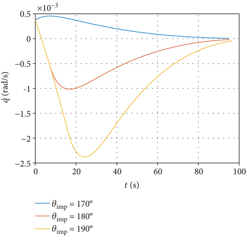
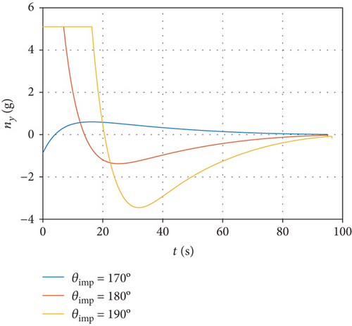
Similar conclusions can be made in contrast to the previous line-of-sight constrained MPSP guidance method. As shown in Figure 4(a), the interceptor is able to reach the desired position under the command of the impact angle constrained MPSP guidance algorithm. Figures 4(b) and 4(c) imply that the terminal constraints of both impact angle and line-of-sight rate have been satisfied. In Figure 4(d), the overload command gradually converges to zero and therefore provides a favorable initial condition for the endgame interception.
4.4. Full Trajectory Interception
- (1)
Initial position of interceptor is 0,12,0 km, initial velocity is 360 m/s, and initial flight path angle and velocity azimuth angle are both 0°
- (2)
The interceptor’s rocket works in two levels, the first level lasts 2 s and produces 30kN thrust, while the second level lasts 22 s and produces 8 kN thrust
- (3)
The hypersonic target maintains pullup and pulldown gliding trajectory with an initial altitude of 60 km and speed of 5100 m/s
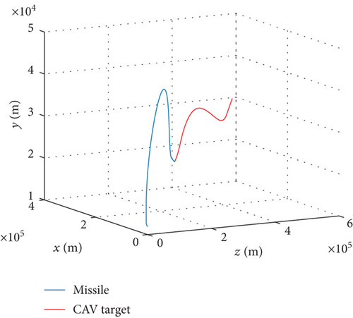
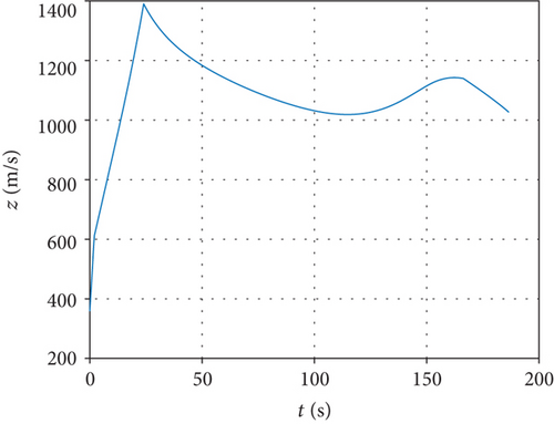
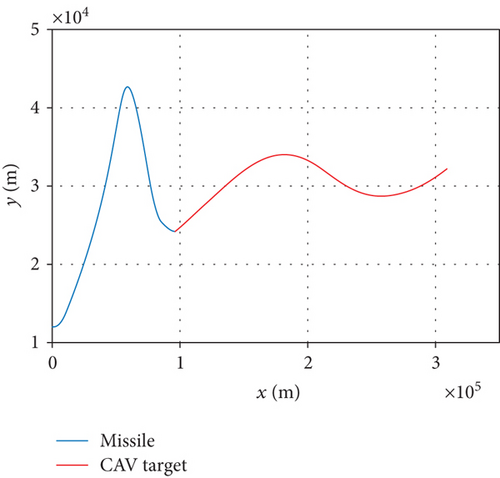
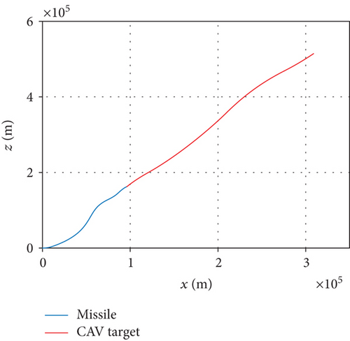
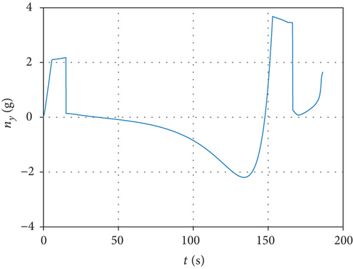
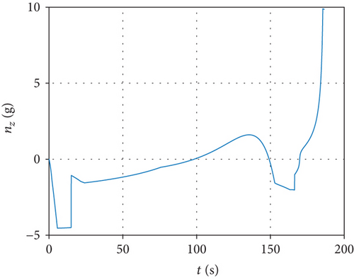
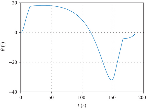
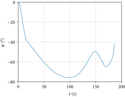
Assuming that the interceptor is released once the missile-target range meets the desired distance, simulation results are shown in Figure 5. From that, we can see the progress of the interceptor. After launching from an airborne platform, the interceptor climbs to upper air under trigonometric guidance. Until 15.00 s later, it turns to midcourse phase and keeps accelerating. A maximum speed of 1389.92 m/s is achieved when the rocket engine burns out at 24.00 s. The trajectory reaches a maximum altitude of 42.67 km after 113.36 s. Separation from booster rocket appears at 166.33 s when the handover range is reached and terminal guidance takes over. The final miss distance is 2.47 m after 186.44 s flight, which demonstrates the correctness of the proposed guidance strategy.
5. Conclusions
This paper proposes a novel midcourse guidance strategy for interceptors against near-space hypersonic targets. The characteristics of hypersonic weapon defense and the requirements of midcourse guidance design for interceptors are analyzed. The line-of-sight coupled interception model is established in a three dimensional space. Under the assumption that the closing velocity remains constant and the target maneuver is briefly negligible, a MPSP method-based suboptimal midcourse guidance law is derived for two different purposes that either satisfies the terminal line-of-sight angle constraint or satisfies the terminal impact angle constraint. Results indicate that the designed angle can be realized with maximum error less than 0°. In addition, the line-of-sight rate approaches zero at handover time, which implies that the final overload command can converge to a small value. In the interception of a hypersonic gliding target, the final miss distance turns out to be 2.47 m, which proves the effectiveness of this guidance law.
Conflicts of Interest
The authors declare that they have no conflicts of interest.
Acknowledgments
This research was supported by the National Natural Science Foundation of China (Grant no. 61503301) and the National Safety Academic Fund (Grant no. U1630127).
Open Research
Data Availability
The data used to support the findings of this study are available from the corresponding author upon request.


