Experimental and Numerical Investigation of Blast-Induced Vibration for Short-Delay Cut Blasting in Underground Mining
Abstract
It is essential to control the damage to the surrounding rock and engineering structures in the process of cut blasting with a single free surface in underground mining. To reduce vibration induced by cut blasting, this paper proposes short-delay cut blasting, in which blast holes that are near each other are sequentially initiated with short-delay times. Experimental tests of cut blasting were conducted in a roadway in the Shaxi copper mine to compare the peak particle velocity (PPV) and frequency characteristics of simultaneous blasting and short-delay blasting. Numerical modelling was then developed to study the influence of short-delay times on blast vibration. The accuracy of the numerical simulation was verified by the comparison of the test and simulated data of single-hole blasting. The results show that the amplitude reduction ratio (ARR) value increases gradually with the increase in delay intervals, and the vibration reduction for delay intervals smaller than 6 ms is very limited, particularly in the near field. The principal frequencies (PFs) for short-delay blasting are similar to those for simultaneous blasting, which implies that the frequencies do not increase directly with the decrease of the delay intervals. The experimental tests also show that the mean frequencies (MFs) for the 8 ms delay are slightly higher than those for the 0 ms delay blast. In the case of ensuring the rock breaking of cut blasting, longer delay intervals of 8∼10 ms are beneficial to further reduce PPV in practical blasting.
1. Introduction
Hard rock fragmentation by blasting is the most widely used and cost-effective means in mining and construction operations. However, only a part of the energy released during blasting is utilized directly for breaking rock within the target range, while the rest causes damage to the surrounding rock, structures, and environment owing to ground vibration, noise, flying rocks, backbreak, and air blasts [1, 2]. Among all the negative effects, ground vibration induced by blasting, which adversely affects the stability of surrounding structures and residences, is regarded as the most severe of blasting hazards. To reduce blast-induced vibration, delay blasting, which has been proved to cause less vibration than simultaneous initiation, is adopted in practical blasts [3, 4]. However, the pyrotechnic delay detonators widely used in blasting engineering have large delay errors; thus, they are often unable to meet the requirements of fine blasting technology [5]. The newly invented and applied electronic detonators make precise short-delay blasting possible, as the delay error is normally less than 1 ms [6, 7].
The previous studies on precise delay blasting with electronic detonators focused more on the feasibility of fragmentation improvement with the improvement of delay precision [8–13]. Most scholars have, through many field experiments and trials, arrived at the consensus that precise delay blasting using electronic detonators had significant advantages in improving rock fragmentation. On the other hand, few studies have focused on the vibration effect induced by blasting with short delays. Blair [14] noted that there was no distinct difference in peak vibration between pyrotechnic and electronic delays. Xu et al. [15] studied the energy distribution of precise delay blasting and found that it could control the input of low-frequency energy. Qiu et al. [16] focused on the vibration interference and reduction mechanisms of short-delay blasting by superimposing a single-hole blasting vibration signal. However, no consensus has been reached so far on the influence of precise delay blasting with electronic detonators on blast-induced vibration. In addition, previous studies on the vibration effect of precise delay blasting did not consider the influence of free surfaces.
There is normally only one single free surface for underground cut blasting, which increases the difficulty of the blasting construction. To improve the blasting efficiency of cut blasting, there can be a set of blast holes near each other that are initiated at the same nominal delay time to create enough compensating space and new free surfaces for subsequent blasts. Reducing the harmful vibration induced by cut blasting with large charge weight per delay is a critical challenge in underground mines [17]. To solve this problem, this paper proposes short-delay cut blasting in underground rock excavation to reduce blast-induced vibration. In the short-delay cut blasting, the blast holes are sequentially initiated with small delay intervals. The delay intervals between cutting blast holes should not be too long; otherwise, a common blasting crater cannot be obtained. If there is significant potential to reduce vibration in the short-delay cut blasting, it would be of great interest to the underground mining industry. Thus, the purpose of this research is to investigate the possibility of vibration reduction for short-delay cut blasting.
It is well known that peak particle velocity (PPV), frequency, and duration time are the three parameters used to assess the blast-induced vibration in rock mass [18]. PPV has been considered as the most suitable parameter to evaluate the possible damage caused by blasting for a long time, and comprehensive investigations on PPV have been conducted by many researchers [19, 20]. In practice, some empirical criteria mainly based on the PPV in rock mass are used to assess the blast-induced vibration. Apart from PPV, it is also necessary to understand the frequency contents of vibration signals. In mining engineering, the principal frequency (PF) is also used in some criteria and specifications to evaluate the allowable vibration limits [21, 22]. Wu and Hao [23] and Hao et al. [24] derived empirical PF attenuation relations based on numerical simulation and field-blasting tests in granite mass. In addition to PF, the mean frequency (MF) proposed by Yang et al. [25] is considered to give more accurate characteristic of frequency composition.
Many uncontrollable factors, such as rock property, joint fracture, and nature of the terrain, have important influence on blasting performance; thus, it is expensive to study the characteristics of blast-induced vibrations simply by field-blasting tests [25, 26]. With the rapid advancements in computer technology, numerical methods are used to investigate the characteristics of blasting [27]. This paper studied the vibration induced by short-delay cut blasting through both experimental tests and numerical simulation. Cut blasting tests carried out in an underground mine are used to compare the vibration of simultaneous blasting and short-delay blasting. Subsequently, the related numerical modelling is performed to systematically study the influence of short-delay intervals on blast-induced vibration.
2. Field Experiment
To compare the vibrations induced by the simultaneous blasting and short-delay blasting and to obtain the characteristics of vibrations induced by blasting with different delay intervals, we conducted some experimental tests in Shaxi underground copper mine using four-hole schemes with a single free surface.
2.1. Experimental Setup
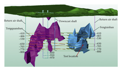
The test mine, the Shaxi copper mine, which is located in the southeast of Hefei city in Anhui province, China, is a newly constructed copper mine with a designed annual ore quantity of 3300 kt. The ore grade is 0.59% copper with a total reserve of 80.9 million tons. The ore body type is porphyry copper, and the surrounding rock types are massive rock and stratified rock. The main ore body is divided by fault F7 into two ore blocks, which are called Tongquanshan ore block and Fengtaishan ore block. As shown in Figure 1, the tests were carried out at the −650 m level of the Fengtaishan ore block. The parameters of the rock mass are as follows: the density is 2700 kg/m³, the Poisson ratio is 0.3, the elastic modulus is 51.96 GPa, the compressive strength is 169.85 MPa, and the tensile strength is 7.16 MPa [17].
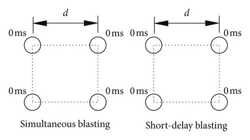
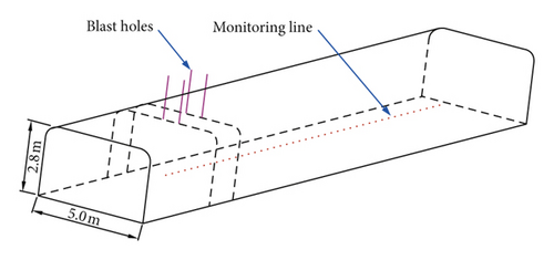
The tests were carried out in a roadway with a width of 5.0 m and height of 2.8 m. First, single-hole blasting tests with a single free surface were conducted to investigate the propagation law of seismic waves. The hole diameter and depth are 89 mm and 0.8 m, respectively. Next, blasting tests with four holes were carried out to study the vibrations induced by simultaneous blasting and short-delay blasting. The delay schemes can be seen in Figure 2. A short delay of 8 ms was used to compare the vibration of the short-delay blasting against that of simultaneous blasting with a delay of 0 ms. The diameter and depth of the blast holes were 89 mm and 1.2 m, respectively. In actual cases of cut blasting in underground mines, the distance between adjacent holes is 0.8 m. A coupling charge structure with emulsion explosive is used in the present study. The detonation velocity and density for the explosive are 3200 m/s and 1000 kg/m3, respectively.
2.2. Vibrations Induced by Single-Hole Blasting
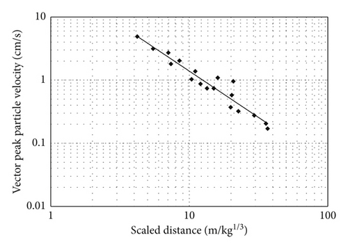
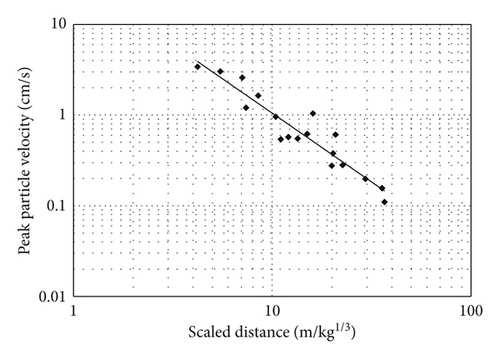
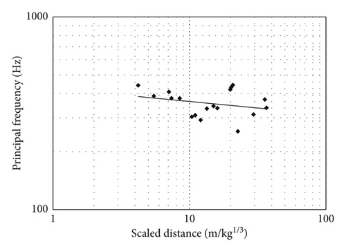
3. Comparison of Simultaneous and Short-Delay Blasting
Blasting tests with four blast holes for 0 ms and 8 ms delayed blasts were conducted, and the velocity time histories were measured to contrastively investigate the characteristics of peak particle velocity and frequency.
3.1. Comparisons of PPV
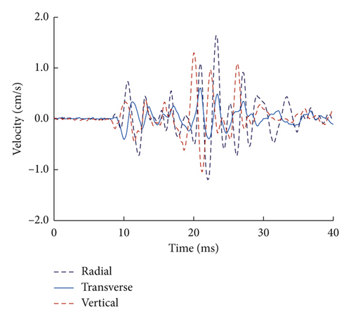
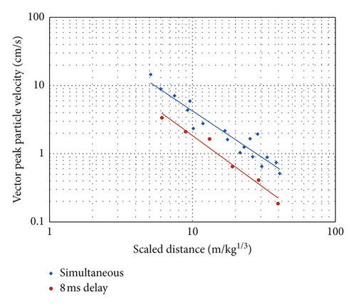
As seen from Figure 8, simultaneous blasting produced larger PPV as a function of SD compared to the 8 ms delayed blast. This is mainly because the charge weight per delay for the 8 ms delay is much smaller than for simultaneous blasting, and the total energy for the 8 ms delay is released discretely, while in the 0 ms case, energy is released nearly simultaneously. It is widely accepted that delay blasting can effectively reduce vibration amplitude. However, in practical blasting, long-delay intervals (normally longer than 25 ms) are applied for vibration reduction. It is doubtful whether delay blasting with short-delay intervals could reduce PPV and, if so, to what extent short-delay blasting could reduce PPV. The test in this study shows that it is efficient to reduce the PPV for the delay of 8 ms.
3.2. Comparisons of Vibration Frequencies
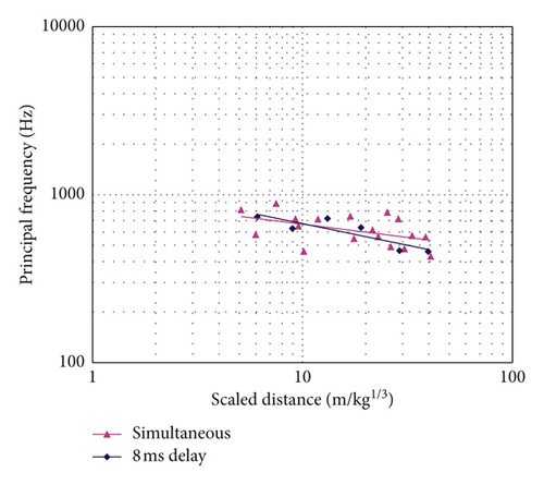
It can be seen that the 0 ms and 8 ms delayed blasts produce similar principal frequencies, which is inconsistent with the popular conception. This is because the spectral banding for small delay intervals is not as obvious as that for large delay intervals, for which the dominant frequencies are mostly determined according to the delay intervals between blast holes. As noted by Blair [34], it is impossible to control the frequencies according to the delay intervals, for delays intervals smaller than 10 ms. The results shown in Figure 9 indicate that for short-delay blasting, the principal frequencies are more likely to be determined by the site conditions rather than the delay intervals between blast holes. It is interesting to note from Figure 9 that the α value for the 8 ms delay is smaller than the 0 ms delay, which indicates more readily attenuated principal frequencies.
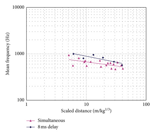
Figure 10 presents the MF comparisons for the 0 ms and 8 ms delayed blasting versus scaled distance. As shown, the mean frequencies for the 8 ms delay are slightly higher than those of the 0 ms delay blast. As seen in Figure 9, the two delays have similar principal frequencies; the higher mean frequencies for the 8 ms delay indicate that there is more energy in the high-frequency content compared with the 0 ms delay case. The possible reason for this phenomenon is that for the 8 ms delay blast, when a later blast hole detonates, initial cracks are formed around the former detonated blast hole. Hence, when the compressive stress waves caused by the later detonated blast hole reach the cracks, they are partly reflected as backpropagating rarefaction waves. The reflected rarefaction waves are superimposed onto the initial compressive stress waves and lead to lower loading pressure with a smaller peak, shorter rising time, and shorter duration [25]. In addition, with the reduction of loading duration, the spectrum of the loading moves into the region of higher frequencies. As the initial cracks are very local around the blast hole when the later blast hole detonates, only a fraction of the compressive stress wave is reflected. Therefore, the principal frequency remains unchanged, but the increase in the high-frequency content makes the mean frequency of an 8 ms delay larger than that of a 0 ms. In addition, it can also be observed from Figure 10 that the α value for the 0 ms delay is larger than that for the 8 ms delay. This is because the high-frequency content attenuates faster than low frequency in rock mass.
4. Numerical Simulation
The experimental study described above preliminarily compares the characteristics of blast-induced vibrations of simultaneous blasting and short-delay blasting. Limited by experimental conditions, the systemic influence of short-delay times on blast-induced vibration is not revealed above. This is studied in this section by numerically modelling the blasting test using the LS-DYNA program, whose accuracy in simulating delay blasting in a rock mass has been proven in previous studies [13, 25].
4.1. Numerical Model
According to the blasting conditions shown in Figure 2, a three-dimensional numerical model measuring 140 × 80 × 80 m (length × width × height) is developed to simulate the vibrations induced by simultaneous blasting and short-delay blasting, as illustrated in Figure 11. In the model, the dimension and layout of the blast holes are in accordance with the experimental tests. Hexahedron-shaped brick elements with eight nodes and different element sizes are used in the numerical model. Suggested by Kuhlemeyer and Lysmer [35], the mesh size should be shorter than 1/8–1/10 of the wavelength in general to reduce any wave distortion. Convergence tests are conducted to determine the sizes of elements until the difference of the modelling results between two consecutive element sizes is less than 5%. Based on the convergence test results, the element size ranges from 0.2 m near the charge to 2.0 m at the border, and the model has a total of 902,820 elements with 944,974 nodes. In accordance with the experimental situation, nonreflecting boundaries are applied to the six outside surfaces of the model and free boundaries are enforced on the internal surfaces of the model. In the numerical model, the high explosive and the stemming are solved using the Eulerian method and the rock mass is solved using the Lagrangian method.
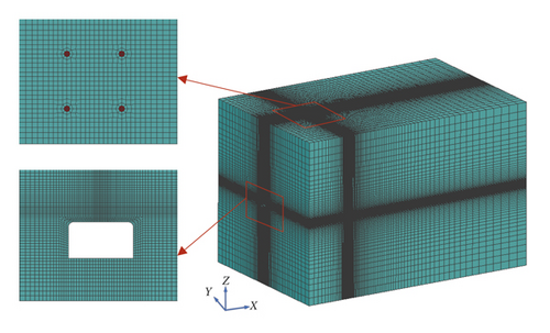
Rock masses in the immediate vicinity of the charge will undergo high pressure and large strain instantaneously. In the present study, the MAT_BRITTLE_DAMAGE (MAT_96) material model is adopted to simulate the response of rock mass. It is an anisotropic brittle damage model designed for a wide variety of brittle materials, allowing progressive degradation of tensile and shear strengths across smeared cracks that are initiated under tensile loadings. The details of the brittle damage model can be seen in [36]. The material properties of rock in the test roadway are used in this simulation. Values for the fracture toughness, shear retention, and viscosity for the rock mass are not available from the experimental data. Therefore, parametric tests are carried out to adjust the appropriate values by comparing the simulated vibration with the measured vibration waves.
Material Type 5 of the LS-DYNA (∗MAT_SOIL_AND_FOAM) is used for the stemming. The parameters of stemming in the simulation are listed in Table 1 [39]. In the table, ρ is the density, v is Poisson’s ratio, ET is the shear modulus, c is the cohesive force, μ is the friction coefficient, and φ is the internal friction angle.
| ρ (kg/m3) | v | ET (GPa) | c (MPa) | μ | φ (°) |
|---|---|---|---|---|---|
| 2700 | 0.19 | 16 | 0.018 | 0.7 | 35 |
4.2. Demonstration of Numerical Modelling
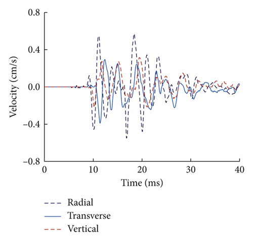
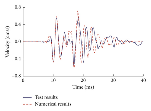
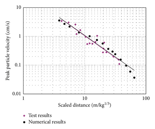
Numerical simulation of blast-induced vibration for a single-hole case is firstly carried out to verify the accuracy of the model. The comparisons of the tested radial velocity time history and simulated waveform in the X direction for the single-hole blasting at a distance of 15 m are plotted in Figure 12. It can be seen that the simulated waves, including peak velocities and frequencies, agree well with the measured results. The peak velocity of the numerical result is slightly larger than that of the tested waves. This might be attributed to the fact that the numerical model assumes a continuous and homogeneous medium while in reality, there could be many fractures and joints in the site. Figure 13 shows the comparison of the attenuation of PPV for tested radial velocity time history and the simulated waves in the X direction versus scaled distance from the charge centre. Considering the randomness of the test site, it can be concluded that the numerical model adopted in the present study is feasible in simulating blast-induced vibration in rock mass.
4.3. Influence of Short Delays on Vibration
Using the above numerical model with LS-DYNA, numerical simulations of the influence of short-delay intervals on blast-induced vibration are carried out. To form a common blasting crater, the delay intervals between blast holes in cut blasting should be less than the formation time of a new free surface [17]. Practical blasting and experimental tests show that the formation time of a new free surface is approximately 20 to 30 ms [40, 41]. In this study, a total delay of 30 ms is selected, and the delay intervals of 0 ms, 2 ms, 4 ms, 6 ms, 8 ms, and 10 ms between blast holes are considered in this simulation.
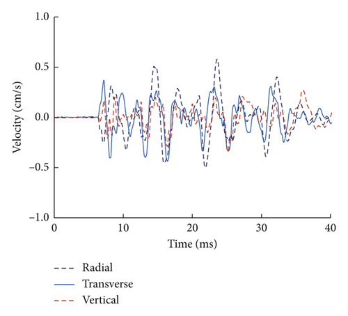
Along the monitoring line shown in Figure 3, 16 target points spaced at every 5 m are specified to record the simulated velocity time histories, at which the PPV are derived. Figure 14 shows the simulated velocity time histories corresponding to delay intervals of 0 ms and 8 ms at the same distance of 20 m from the charger centre. As seen, the velocity time histories in the X direction have the largest peak values among all the three components, which is in accordance with the measured waves in the test. In addition, it is found that the 0 ms case has larger peak values than the 8 ms case in all the three directions, which demonstrates the feasibility of vibration reduction of short-delay blasting compared with simultaneous blasting.
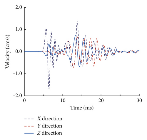
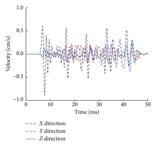
Figure 15 shows the simulated PPV at recording points along the monitoring line for different delay intervals. It can be seen that the PPVs attenuate very quickly with the increase in the distance from the charger centre, irrespective of the delay intervals. As shown, we can clearly see that the 0 ms case has the largest PPV values at all the recording points in the three components. This indicates that simultaneous blasting is the most unfavourable condition for vibration control in practical blasting, which we need to make every effort to avoid. It is interesting to note that delay blasting with any delay interval is feasible for vibration reduction, as the PPV values of the 2 ms delay case are smaller than those of the 0 ms case.
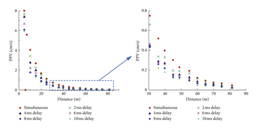

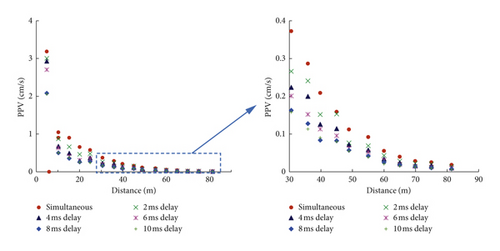
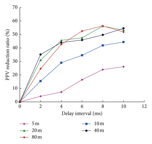
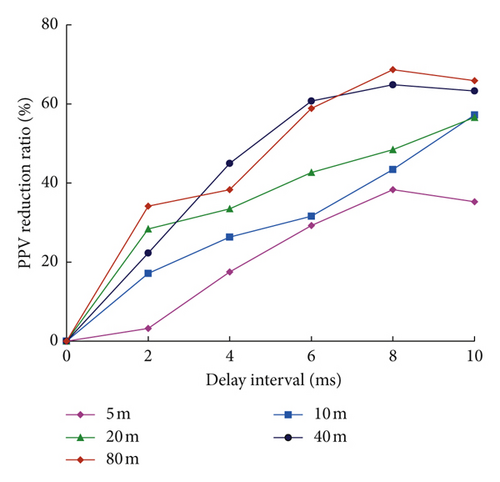
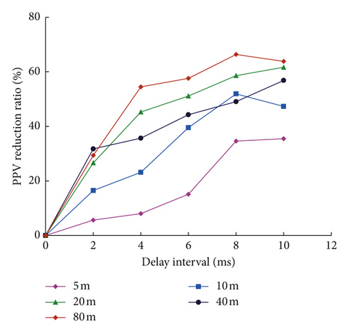
Figure 16 shows the calculated ARR of simulated waves versus delay intervals at different distances. It can be seen that the ARR value increases gradually with the increase in delay interval in the time range of 0∼8 ms. It is widely accepted that the wave superposition of blast-induced vibration occurs in the peak range of velocities. Delayed blasting changes the energy releasing form as the total energy of the charge is released in a time range rather than in an instantaneous time. Therefore, with the increase in delay interval, the superposition of vibration waveforms induced by successively detonated blast holes is reduced, and thus, the PPV is reduced. It is noted that the ARR fluctuates for the cases of 8 ms and 10 ms. This might be attributed to the fact that the optimum delay interval is mainly influenced by the principal vibration period of vibration waveform induced by single-hole blasting [15]. It is also observed from Figure 16 that the ARR values at different distances are apparently different. The ARR values at shorter distances are smaller than at farther distances for the same delay intervals. Taking the X direction for an example, as shown in Figure 16(a), the ARR values at a distance of 5 m are all smaller than that of 10 m for the same delay intervals and the values of 10 m are smaller than other longer distances. As shown in Figure 16(c), the ARR values for the cases of 2 ms, 4 ms, and 6 ms at a distance of 5 m are all less than 20%, while at a distance of 80 m, the ARR value is 66.35% for the case of 8 ms. This indicates that at long distances, delay blasting with short-delay intervals leads to great vibration reduction, but in the near field, the vibration reduction effect is not obvious. To obtain similar reduction effect, relatively longer delay intervals are needed in the far field. This is because the blast-induced seismic action is realized by the response deformation of rock mass far away from the elastic deformation zone [43]. The propagation velocity of blast-induced seismic is far less than the velocity of elastic deformation wave in rock mass; thus, the energy release of the ground vibration will not change significantly for the different delay intervals. Therefore, in order to obtain considerable vibration reduction in the whole distance range, relatively long-delay intervals are preferentially selected in cut blasting in the case of ensuring the formation of a common blasting crater.
The simulated waves are calculated by the Fourier transform, and based on equation (5), the principal frequencies are obtained. Figure 17 shows the principal frequencies of simulated waves versus delay intervals at different distances in the Z direction. It can be seen that as the distance increases, the principal frequency decreases for a specific delay interval. This illustrates the attenuation characteristic of blast-induced vibration frequency, which is in accordance with the tested vibration waveform in Section 3. It can also be seen from Figure 17 that the PFs for different delays are similar, which are consistent with the test results. The differences of principal frequencies between different delays are very small. It is also observed that there is no increasing trend for the principal frequencies as the delay intervals decrease. Again, the numerical results show that the popular conception that the frequencies become higher with the decrease in the delay intervals is not suitable for blasting with delay times smaller than 10 ms. However, it is impossible to use the three-dimensional model to simulate the reflection of the compressive stress waves induced by the later detonated blast hole on the initial cracks caused by the former detonated blast hole under current computer resources, and therefore, the MFs of different delay intervals are not compared here.
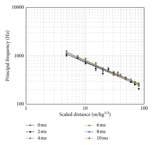
The test and numerical results show that the PFs for short-delay blasting are similar with simultaneous blasting. It indicates that a change in delay time from 0 ms to small delay intervals would not increase the possibility of structural resonance. In addition, the above test and simulation also show that short-delay blasting could effectively reduce PPV compared with simultaneous blasting. Therefore, it is of great value to reduce PPV with similar principal frequencies via short-delay cut blasting.
5. Conclusions
This paper proposes short-delay cut blasting to reduce blast-induced vibration in underground mining. Single-hole blasting tests with a single free surface were firstly carried out in a roadway in the Shaxi copper mine to obtain the site-specific attenuation relations of PPV and PF of vibration waves. Cutting blasts with four blast holes for delay intervals of 0 ms and 8 ms between blast holes were then conducted to compare the characteristics of PPV and frequencies. A numerical model was developed to investigate the blast-induced vibration of short-delay blasting with a single free surface. The measured data of single-hole blasting were used to verify the accuracy of the numerical simulations, and a very good agreement between the measured and numerically simulated data was obtained. The numerical model with four blast holes was used to systematically investigate the influence of short-delay intervals on PPVs and PFs of vibration waves.
The experimental tests and numerical results show that the ARR value increases gradually with the increase of delay intervals. The vibration reduction for delay intervals smaller than 6 ms is very limited, particularly in the near field. The principal frequencies for short-delay blasting are similar to those for simultaneous blasting, which implies that the frequencies do not increase directly with the decrease of the delay intervals. The experimental tests also show that the mean frequencies for the 8 ms delay are slightly higher than those for the 0 ms case, which may be caused by the reflection of the compressive stress waves caused by a later detonated blast hole on the initial cracks caused by a former detonated blast hole.
The experimental tests and numerical simulation in the present study show that it is of great value to reduce PPV with similar frequencies via short-delay cut blasting. In practical blasting, longer delay intervals such as 8∼10 ms are preferentially selected for further reducing PPV in the case of ensuring the rock breaking of cut blasting.
The influence of the reflection effect (the reflection of the compressive stress waves caused by a later detonated blast hole on the initial cracks caused by a former detonated blast hole) on the frequency characteristics of short-delay blasting cannot be ignored. However, owing to limited current computing resources, it is impossible to quantify the influence of the reflection effect. The precise frequency characteristics of short-delay blasting may be determined in the future with the help of supercomputers.
Conflicts of Interest
The authors declare that they have no conflicts of interest.
Acknowledgments
This work was supported by the National Natural Science Foundation Project of China (51874350) and the National Key R&D Program of China (2017YFC0602902). The support provided by the China Scholarship Council (CSC) during the visit of Xianyang Qiu to Curtin University is acknowledged. The authors also thank Hong Hao, Yifei Hao, and Jian Cui for their excellent advice.
Open Research
Data Availability
The data used to support the findings of this study are available from the corresponding author upon request.


