A Fast RFID Tag Anticollision Algorithm for Dynamic Arrival Scenarios Based on First-Come-First-Serve
Abstract
Radio-frequency identification (RFID) tag anticollision algorithm is a key technology that affects the performance of RFID systems. In dynamic arrival scenarios, when the tags arrive the reader’s interrogation zone, they cannot participate in the ongoing identification immediately, resulting in longer waiting time and tag miss. Focusing on solving this problem, based on blocking technology, dynamic frame-slotted ALOHA (DFSA) algorithm, and the first-come-first-serve (FCFS) idea, a fast RFID tag anticollision algorithm for dynamic arrival scenarios is proposed, named as “DAS-DFSA algorithm”. By optimizing the instruction structure and identification process, the DAS-DFSA allows the new arrival tag to immediately participate in the ongoing identification process, the tag’s waiting time is shortened, and the miss rate is reduced. DAS-DFSA not only adopts blocking technology to prevent the collision between the arrival tag and waiting tag but also uses unequal-length slots to reduce the communication time overhead. Simulation results show that the identification speed of the algorithm is significantly improved and high system efficiency is guaranteed. Under the same operating conditions, compared with similar algorithms, the waiting time is shortened by more than 44.548% and the identification speed is improved by at least 39.053%. More importantly, it can provide the instant-on-service for dynamic arrival tags and can fully meet the requirements of fast identification of tags in different dynamic arrival scenarios.
1. Introduction
Radio-frequency identification (RFID) technology is one of the key technologies of the Internet of Things. It has been widely used in industrial, agricultural, and commercial production systems, such as warehouse management, logistics tracking and supply chain [1–4] goods manufacturing line [5], ticketing systems [6], and highway electronic toll collection (ETC) system [7]. According to whether the tag moves or not, the RFID application scenarios can be divided into static scenarios and dynamic arrival scenarios [3, 5, 6]. The number of tags in static scenarios is relatively stable, such as warehouse goods and libraries. In the dynamic arrival scenario, the tag arrives randomly or stably and periodically during the identification process of each frame and can quickly leave the reader’s interrogation zone. So, the number of tags in dynamic arrival scenarios changes at any time, such as RFID-tagged products on the conveyor belt, vehicles passing through the toll station, and cattle and sheep passing through the gate.
Ultrahigh frequency (UHF) RFID technology has the advantages of fast identification speed and strong penetration power. Passive tags are driven by radio frequency signals from the reader to avoid dependence on batteries. Therefore, passive UHF RFID technology based on EPC C1G2/ISO 18000-6C has been widely studied and applied [8–11]. The essential components of an RFID system include RFID tags, readers, and servers [12]. RFID technology enables two-way communication between the reader and tag by sharing wireless channels. However, when multiple tags respond simultaneously, the collision of signals will lead to the failure to identify any tags [13], which reduces the system efficiency. The anticollision algorithm provides a solution to this problem and has achieved many research results [8, 11, 14–17]. RFID tag anticollision algorithms are mainly divided into tree-based and ALOHA-based algorithms [8, 11, 18–20]. Tree-based algorithms are less efficient when the number of tags is large [19], and compared with the ALOHA-based algorithm, the waiting time is too long [20]. In contrast, ALOHA-based algorithms are probabilistic [19, 21] and assign an amount of slots for tags randomly chosen to transmit data [19]. The frame-slot ALOHA (FSA) algorithm is preferred because of its simplicity and efficiency [19]. It uses a fixed frame length during the identification process [22]. Since the frame length cannot be adjusted in time, the system efficiency will decrease significantly when collisions occur continuously. To overcome the shortcomings of the FSA algorithm, the dynamic frame-slotted ALOHA (DFSA) algorithm was proposed [23]. The biggest improvement is to quickly adjust the frame length of the next frame to the optimal value based on the identification result of the current frame, so as to obtain the maximum system efficiency. These types of algorithms researches focus on the optimal distribution of tags’ responses in a timeline [24].
In static scenarios, existing anticollision algorithms can achieve high system efficiency and identification speed [25]. However, when these algorithms are applied to dynamic arrival scenarios, the tag miss rate increases since RFID tags cannot wait long enough to be identified within the reader’s interrogation zone. Therefore, these algorithms are not suitable for dynamic arrival scenarios [10]. The ALOHA-based anticollision algorithm is the de facto MAC protocol for the passive RFID system because of its efficiency, and it is easy to implement [9, 19]. Moreover, DFSA-based anticollision algorithms have been used to investigate the rapid identification of dynamic arrival scenarios [3, 5, 6]. Therefore, this paper also focuses on the ALOHA-based anticollision algorithm.
- (1)
The new arrival tag is allowed to immediately participate in the identification process of the ongoing frame to shorten the waiting time
- (2)
The blocking technology is adopted to avoid the collision between the new arrival tag and the waiting tag by isolating each other and selecting response slot
- (3)
Unequal-length slots are adopted to reduce the communication time overhead to improve the identification speed
- (4)
Detailed and clear frame structure, identification process, and instruction structure optimization scheme are given
Simulation results show that the proposed DAS-DFSA algorithm is superior to other similar algorithms in terms of waiting time, miss rate, and identification speed in dynamic arrival scenarios.
The structure of this paper is as follows. In Section 1, some relevant background and motivation of this work are introduced. In Section 2, the related anticollision algorithms, tag number estimation methods, tag arrival rate, and system efficiency calculation methods are reviewed. All the notations definition used in this paper are listed in Table 1. In Section 3, the system models of this paper are proposed, mainly including tag dynamic arrival process model, communication sequence model, tag dynamic identification process model, and tag arrival rate model. Then, a new fast RFID tag anticollision algorithm for dynamic arrival scenarios is proposed in Section 4. Moreover, simulation results are discussed in Section 5. In Section 6, the conclusions of this research work are given.
| Notations | Meaning and explanation |
|---|---|
| Sc | Number of collision slots |
| Se | Number of empty slots |
| Ss | Number of success slots |
| P(n|Ss, Sc, Se) | Probability of occurrence under the condition (n|Ss, Sc, Se) |
| Number of tags participate in one frame | |
| TSs | Duration of success slot |
| TSe | Duration of empty slot |
| TSc | Duration of collision slot |
| Usys | The system efficiency of one frame |
| Usys(n) | The system efficiency of the first n frame |
| Ssi | Number of success slots in the i-th frame |
| Li | Frame length of the i-th frame |
| Fi | The i-th frame |
| P | Tag identification process |
| Nci | Number of unidentified tags in the i-th frame |
| Nai | Number of new arrival tags in the i-th frame |
| λi | Arrival rate of the i-th frame |
| Sij | The j-th slot in the i-th frame |
| Ssj | Number of success slots after j-th slot |
| Scj | Number of collision slots after j-th slot |
| Sej | Number of empty slots after j-th slot |
| Tij | Time after j-th slot in the i-th frame |
| Naij | Number of new arrival tags after j-th slot in the i-th frame |
| SIDt | Tag random slot number |
| SIDc | The current slot number of one tag |
| SIDw | The maximum slot number that can be selected by the waiting tag |
| SIDl | The minimum slot number that can be selected by the new arrival tag |
| SIDwi | Number of unidentified tags in the i-th frame |
| SIDai | Number of new arrival tags in the i-th frame |
| RN16 | 16-bit random number |
| EPC | 96-bit electronic product code |
| Ack | The Ack instruction |
| IndicateWait | The IndicateWait instruction |
| IndicateArrival | The IndicateArrival instruction |
| Indicate | The IndicateWait or IndicateArrival instruction |
| Start | The Start instruction |
2. Related Work
In dynamic arrival scenarios, to quickly identify the arrival tag, the ALOHA-based CDFSA [3] and MT-EDFSA [6] algorithms have been proposed to solve the collision problem. Although both CDFSA and MT-EDFSA allow new arrival tags to participate in the identification of the ongoing frame and have achieved good results. However, CDFSA cannot prevent collisions between the new arrival tag and the waiting tag, resulting in longer waiting time. Conversely, MT-EDFSA algorithm can solve this problem by optimizing the instruction structure and the frame structure, but all slots take up equal-length time, which leads to excessive communication time overhead, longer waiting time, and low identification speed.
For DFSA-based algorithms, frame length is the key factor to successfully get high system efficiency [19]. Dynamic arrival scenarios are different from static scenarios, and the reader does not know not only the number of unidentified tags but also the number of upcoming tags. Together, they determine the optimal frame length, which ensures the system efficiency of the algorithm and shortens the waiting time [3, 6]. Therefore, it is important to estimate the number of tags in dynamic arrival scenarios.
2.1. Tag Number Estimation
In the above algorithms, the MAP method can be applied to the estimation of the number of tags under any identification result. The average estimated error is about 5%, and the error is the smallest [3], but the calculation cost is very large. In contrast, the Shoute’s method is the simplest, fastest, and widely used one.
2.2. Tag Arrival Rate
The number of arrival tags depends on the arrival rate. There are two main definitions of tag arrival rates. One is slot-based arrival rate definition, which is calculated as the ratio of the number of arrival tags to the frame length or the number of slots, i.e., the number of tags arriving in each slot [28]. The other is time-based arrival rate definition, which is calculated as the ratio between the number of arrival tags and the time length of frames, i.e., the number of arrivals per unit time [10]. Before the start of a frame, the frame length, i.e., the number of slots, can be determined. However, as described in Section 3.2, when the duration of different slots is different, the duration of the frame can only be determined at the end of the frame. Therefore, even if the time-based arrival rate is obtained before the start of a frame, the number of arrival tags of the current frame cannot be predicted. Obviously, this definition is applicable to the algorithm that arrival tags take part in the next frame identification [10], but it is not applicable to the algorithm that arrival tags participate in the ongoing frame identification. Conversely, the slot-based arrival rate is suitable for the scenario where arrival tags participate in the ongoing frame identification [3, 6]. The above two definitions are used to measure the arrival rate in different ways, but it is necessary to make a choice according to the specific application scenario.
In dynamic arrival scenarios, the reader considers that the tag arrival event is a composite result of the tag’s arrival and departure within the interrogation zone. The specific arrival quantity and rate cannot be determined in advance and can only be predicted based on the identification result of the previous frame. Since the tag arrival and departure are independent random events and have temporal local correlation, the Poisson process was used to study the tag arrival rate. Nonhomogeneous Poisson processes (NHPP) [29] can be used to simulate the arrival rate as it can reflects changes over time. According to the temporal local correlation of the arrival rate, the time between the previous frame and the next frame is very short and the arrival rate can be regarded as a continuous change. The calculated arrival rate after the end of the previous frame can be used as an estimate of the arrival rate of the next frame [3]. The cosine function, which is very close to the positive distribution density, was also used to simulate the arrival rate in dynamic arrival scenarios [28], and the Dynamic Self-Adaptive Residual Metabolic Gray Model (DSA-RMGM) algorithm was proposed [10]. The modeling length can be adjusted dynamically according to the change of the arrival rate, which overcomes the problem that the prediction accuracy of the gray prediction model decreases when the arrival rate changes dynamically, and can dynamically adapt to the data change.
2.3. System Efficiency
System efficiency is one of the key indicators to measure the performance of the algorithm. In general theoretical analysis, system efficiency is defined as the ratio of the expected number of success slots to the frame length. In practical calculation, the system efficiency function is given by the ratio of the number of success slots to the frame length.
Here, Ssi and Li indicate the number of success slots and the frame length of Fi frame, respectively. The above analysis shows that equations (2)–(4) measure the system efficiency of the algorithm from different dimensions and are essentially consistent. Therefore, it is necessary to choose which equation to use according to the design of the algorithm, for example, equation (3) is more suitable for the algorithm with equal-length slots.
For more accurate and convenient explanation of the issues of interest, Table 1 lists all the important notations used in this paper.
3. System Model
To describe the tag identification process in dynamic arrival scenarios, as in the previous study [3, 5, 6], this paper also assumes that the reader is stationary in a fixed position while the tag is moving through the reader. At the same time, the type and model of the tag are exactly the same in this scenario. Therefore, it can be assumed that the tag automatically switches to the selected activation state after entering the reader interrogation zone [5]. Then, the tag dynamic arrival process, communication sequence, and tag dynamic identification process are modeled. The tag dynamic arrival process model is used to describe the movement of the tag in the real scenario, as well as the definition of the tag state and the state transition condition. The definition of the slot type and duration is given by the communication sequence model. Using the established tag dynamic identification process model, the composition of each frame and the number of tags are analyzed, which lays a foundation for the design of the algorithm.
3.1. Tag Dynamic Arrival Process Model
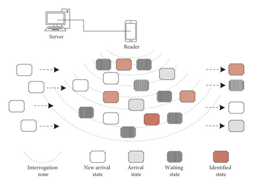
In RFID system, the reader has a specific interrogation zone. When the tag enters the interrogation zone, the tag can respond to the reader’s instructions. If it leaves the reader’s interrogation zone and is not successfully identified, a tag miss event occurs, resulting in fewer inventory counts than the actual number. Figure 1 shows the dynamic arrival process model of tags in a dynamic arrival scenario.
- (1)
New arrival state. A tag that arrives at a frame but does not participate in the identification process of the current frame, i.e., it does not receive instructions and is marked as new arrival state, and such a tag is called a new arrival tag.
- (2)
Arrival state. A tag that arrives at a frame and participates in the identification process of the current frame but has not yet been identified, i.e., it has received instructions and is marked as arrival state, and such a tag is called an arrival tag.
- (3)
Waiting state. The unidentified tag of the previous frame is marked as waiting state, and such a tag is called a waiting tag.
- (4)
Identified state. A tag that has been successfully identified is marked as identified state, and such a tag is called an identified tag.
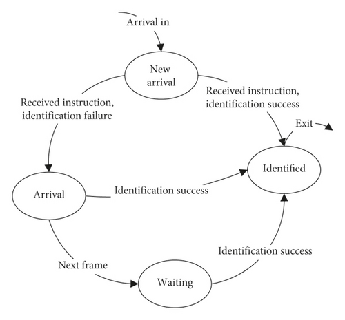
During the identification process, the state of the tag is constantly changing according to the identification. Figure 2 shows the state transition diagram of the tag. When the tag is newly arrival, it is the new arrival state. When it receives a reader’s instruction, if the identification is successful, it will jump to the identified state; otherwise, it will jump to the arrival state. For the arrival tag, if the identification is successfully, it will jump to the identified state; otherwise, it waits for the identification of the subsequent frames until it is successfully identified. The identified tag no longer responds to any instructions from the reader. As shown in Figure 1, when the unidentified tag leaves the reader’s interrogation zone, it is considered that a tag miss event occurs. These tags maybe include waiting tags, arrival tags, and new arrival tags.
3.2. Communication Sequence Model
The reader and the tag realize two-way communication through the wireless channel. All tags in the interrogation zone can receive instructions broadcast by the reader and then determine whether to respond according to the instruction and its state [31]. Obviously, not all instructions will receive a successful response. For communication systems, the communication sequence model is very important. Based on the EPC C1G2 communication sequence model [9], a communication sequence model suitable for this research is designed, as shown in Figure 3.
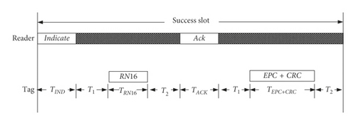
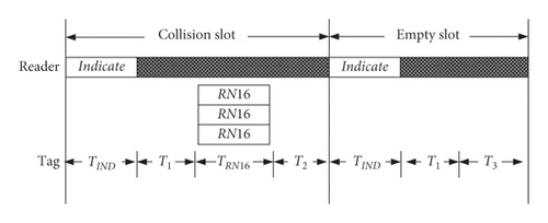
As shown in Figure 3, the reader will broadcast an Indicate instruction in each slot. After the tag receives this instruction, it will decide whether to respond with a random number RN16. Therefore, the reader can receive three different response results in each slot, including one tag response, multiple tag responses, and no tag response. When the reader receives the only one RN16, it marks this slot as a success slot Ss and then sends an Ack instruction carrying the RN16 to all tags. When the tag receives the Ack instruction, it checks its status and whether its own RN16 is equal to the RN16 of the Ack instruction. If they are equal, this tag will reply its own EPC + CRC to the reader and jump to the identified state. Otherwise, the Ack instruction is ignored. When the reader receives multiple tags in response to RN16, the reader cannot identify any tags and marks this slot as a collision slot. If the reader does not receive any response, this slot will be marked as an empty slot. It can be seen that after the end of each frame identification, the reader can count the number of success slots SS, the number of collision slots Sc, and the number of empty slots Se and obviously satisfy the frame length L = Ss + Sc + Se.
Since collision and empty slots are unavoidable, in order to reduce the overall waiting time and improve the identification speed, the less the time wasted by collision and empty slots, the better. Therefore, unlike all slots designed to be of equal length [6], the communication sequence design adopts unequal-length slots, such as the success slot occupies the longest time and the empty slot occupies the shortest time. Another difference is that the Indicate instruction in this communication sequence model is redefined to facilitate notification of the new arrival tag in dynamic arrival scenarios. They are described in detail in Section 4.3.
3.3. Tag Dynamic Identification Process Model
The tag identification process model [10] has been used to analyze the tag identification process, in which the tag arriving within Fi frame participates in Fi+1 frame. In this study, the model is optimized to shorten the tag waiting time, and the new arrival tag arriving within Fi frame immediately participates in the identification of the Fi frame. The tag dynamic identification process model and the intraframe identification process model are designed, as shown in Figures 4(a) and 4(b).


Collisions in the identification process of each frame indicate that there are still unidentified tags or that tags continually arrive in dynamic arrival scenarios. Therefore, if the new arrival tag in Fi frame participates in the identification of Fi frame, the number of tags Ni participating in the identification of Fi frame includes the number of unidentified tags Nc(i − 1) in Fi−1 frame and the number of new arrival tags Nai in Fi frame, as shown in Figure 4(a).
It can be seen that when the number of unidentified tags of the previous frame and the arrival rate of the current frame are determined, the frame length of the current frame can be calculated, and a new frame identification process can be started.
3.4. Tag Arrival Rate Model
The tag arrival in dynamic arrival scenarios includes stable arrival and random arrival, such as RFID-tagged products on the conveyor belt and cattle and sheep passing through the gate. The tag arrival rates of the two cases can be modeled according to queuing theory and normal distribution theory, respectively.
According to the queuing theory, the condition for stable operation of the system is that the arrival rate cannot exceed the service rate. The reader and tag in the tag identification process can correspond to the service station and customer in the queuing theory, respectively. When the customer arrives at the service station, it begins to wait for service. Due to the limited service rate of the service station, when the customer arrival rate exceeds the service rate of the service station, the service station system is in an unstable working state [10], which may lead to customer queuing or even abnormal service paralysis.
The Poisson random process is a good queuing theory tool. At the same time, the arrival of tags in dynamic scenarios is independent of each other and meets the preconditions of Poisson random process. Therefore, the arrival of tags follows it, and the arrival rate λ is also the mean of the Poisson random process [10].
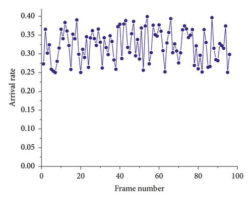
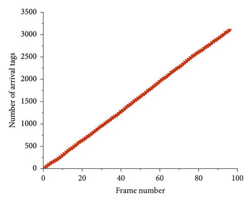
The system efficiency of the optimized DFSA algorithm can reach 0.426 [23, 32]. As shown in Figure 5(a), the tag arrives stably, and it is assumed that the arrival rate of 96 frames is stable in the interval of 0.20 to 0.40, and the frame length L is set to 100. Then, the number of arrival tags of the first 96 frames can be calculated, as shown in Figure 5(b). It can be seen that the arrival rate is stable and the growth rate of the tag number is basically unchanged, which is consistent with the stable arrival rate.
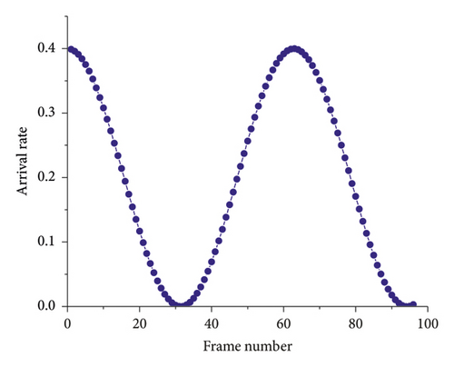
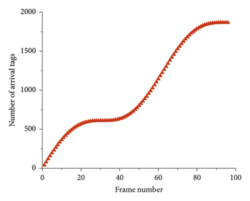
As shown in Figure 6(a), the arrival rate of 96 frames is selected, and it is known that it is 1.5 cycles according to (12). Assuming that the frame length L of each frame is 100, the number of arrival tags of the first 96 frames is obtained, as shown in Figure 6(b). It can be seen that the arrival rate is an unstable line and exhibits periodic changes. More importantly, the number of tags grows at different speeds, which is closer to the real scenario of dynamic arrival tags.
This study conducted simulation based on the arrival rates in these two cases. Obviously, these two cases cover the traditional applications of RFID, such as goods manufacturing line [5], tracking of animals and ranch inventory [33], smart warehouses, and commodity classification. The simulation results are shown in Section 5.
4. The Proposed DAS-DFSA Algorithm
The DAS-DFSA algorithm is based on DFSA and blocking technology algorithms and is dedicated to solving the problem of tag anticollision and fast identification in dynamic arrival scenarios. The main idea is that at the end of each frame, the arrival rate of the next frame can be calculated, and the optimal frame length of the next frame will be set in conjunction with the estimate number of unidentified tags. Blocking technique is used to divide the slot of the next frame into waiting slots and arrival slots and then divide the next frame into two independent processes of waiting identification and arrival identification. The waiting identification process only identifies tags that were not identified in the previous frame, and the arrival identification process only identifies new arrival tags within the frame. Therefore, the slot conflict between arrival tag and waiting tag is reduced, and the new arrival tag participates in the identification of the ongoing frame as early as possible, which reduces the waiting time.
4.1. Basic Design Idea
- (1)
Shorten the waiting time for waiting tags: just like the FCFS idea, the waiting tags arrive to the reader’s interrogation zone earlier than new arrival tags, and it is necessary to ensure that the waiting tag is preferentially identified. Therefore, the frame structure and identification process need to be optimized.
- (2)
Shorten the waiting time for new arrival tags: allowing new arrival tags to participate in the identification within the ongoing frame instead of waiting for the next frame. It can significantly reduce the waiting time. To receive the parameters of the current frame for new arrival tags, the instruction structure need to be redefined.
- (3)
Ensure high system efficiency: the maximum system efficiency can be obtained when the frame length and the number of tags are equal during the identification process. Therefore, it is important to estimate the number of tags participating in each frame to get the optimal frame length.
- (4)
Guarantee high identification speed: to improve the identification speed of the algorithm, the invalid time wasted must be avoided, so unequal-length slots can be used to reduce the communication time overhead as much as possible.
4.2. Frame Structure and Process
According to the blocking technology, in order to prevent the collision between the waiting tag and the new arrival tag, the slots of each frame are divided into two categories: one is the waiting slot and the other is the arrival slot. The identification process consisting of waiting slots is called waiting process, and the identification process consisting of arrival slots is called arrival process, as shown in Figure 7.
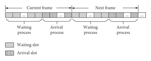
During the identification process, the waiting tag can only participate in the waiting process and select a waiting slot response. Similarly, the new arrival tag participates in the identification of the current frame but can only participate in the arrival process and can only select an arrival slot response. This reduces the probability of a collision between waiting tags and new arrival tags due to the selection of the same slot. The purpose of this design is twofold. One is that the new arrival tag can participate in the identification of the current frame, which can shorten the waiting time for new arrival tags. The other is that the new arrival tag does not compete with the waiting tag for slot resources. This avoids waiting tags to wait for the identification of the subsequent frames due to the collision, thereby shortening the waiting time for waiting tags. As shown by the simulation results in Section 5.1, the combination result of the two will reduce the average waiting time of all tags, which can effectively avoid the tag miss reading caused by long waiting time.
Note that the waiting slot and arrival slot in the frame structure are only used to describe the blocking of the frame identification process. The type and duration of each slot need to be determined based on the identification result, as described in Section 3.2.
4.3. Instruction Structure
The tags that participate in each frame identification include waiting tags, arrival tags, and new arrival tags. The reader broadcasts the Start instruction at the beginning of each frame, and the waiting tag can select a waiting slot as its slot random number SIDt. After frame identification begins, each slot needs to broadcast an Indicate instruction to all tags. The waiting tag receives the current slot number SIDc in the Indicate instruction and determines whether it is equal to its SIDt. If it is equal, it will respond to the reader’s instruction; otherwise, it will not respond. The new arrival tag selects an arrival slot number as its own slot random number SIDt according to the Indicate instruction and determines whether the current slot number SIDc is equal to its SIDt. If it is equal, it will respond to the reader′s instruction; otherwise, it will not respond.
Due to the difference between the instruction information required for waiting tags and new arrival tags in the identification process, two Indicate instructions are designed, which include IndicateWait and IndicateArrival. At the same time, the structure of the Start instruction is also defined, as shown in Figure 8.


The Start instruction is used to start a new read cycle, i.e., a new frame. The parameter Query is similar to the Query command of EPC C1G2. The parameter contains the frame length L. The parameter SIDw indicates the maximum slot number that can be selected by the waiting tag. The waiting tag will select one slot random number SIDt between 1 and SIDw after receiving the Start instruction but will not respond and wait for subsequent identification instructions.
The IndicateWait instruction is used to notify waiting tags and arrival tags to participate in the identification process of each slot. The parameter QueryRep is similar to the QueryRep instruction of EPC C1G2, and the parameter SIDc indicates the slot number currently being executed, and the tag can respond when the SIDt is equal to SIDc. The IndicateArrival instruction is used to notify new arrival tags, arrival tags, and waiting tags to participate in the identification process of each slot. The parameter Query is similar to the Query instruction of EPC C1G2, which includes the frame length L, and the parameter SIDc indicates that the slot number is currently being executed. The parameter SIDl indicates the minimum slot number that can be selected by new arrival tags. The new arrival tag selects one slot random number SIDt between SIDl + 1 and L according to the IndicateArrival identification. The instruction is responded when the tag’s SIDt is equal to SIDc.
The IndicateArrival instruction is equivalent to reinitiating a subframe within a frame, so that the new arrival tag immediately participates in the identification of the current frame. Obviously, the IndicateArrival instruction is longer and takes up more communication time than the IndicateWait. To minimize communication time overhead, its transmission strategy is analyzed in Section 4.5.
4.4. Frame Length Division Strategy
To get the maximum system efficiency, it is necessary to accurately estimate the number of tags to set the optimal frame length. According to the analysis in Section 4.2, each frame identification process includes a waiting process and an arrival process, which are used to identify the waiting tag and the new arrival tag, respectively. Therefore, how to divide the frame and assign the slots number SIDw for waiting process and the slots number SIDa for arrival process is a key issue.
4.5. DAS-DFSA Algorithm
According to the communication sequence model in Section 3.2, Algorithms 1 and 2 give the pseudocode of the reader and the tag end algorithms, respectively. Based on the previous research conclusion, at the beginning of the inventory, the initial frame length L is set to 128 [10, 18]. Assume that the system efficiency of the first frame is the largest, the maximum number of slots SIDw can be set, which can be selected by waiting tags. Then, the reader broadcasts a Start instruction to notify all waiting tags to start the identification process. In the identification process of each frame, each slot broadcasts an IndicateWait or IndicateArrival instruction and the reader will decide whether to send an Ack instruction according to the received response result.
When the slot is a success slot, the Ack instruction is used to send the RN16 to the tag of the success response RN16. Notify the tag to return its EPC information, then this tag has been successfully identified.
-
Algorithm 1: Reader procedure pseudocode of DAS-DFSA.
- (1)
L = 128;
- (2)
Frame_counts = 0;
- (3)
SIDw = L ∗(1–0.368);
- (4)
if (!IdentificationIsEnd)
- (5)
{
- (6)
Frame_counts++;
- (7)
Set [Ss, Sc, Se] to 0;/∗ slot counter ∗/
- (8)
Broadcast Start instruction;
- (9)
Set SIDc to 1;
- (10)
Set SIDl to SIDw;
- (11)
while (!FrameIsEnd)
- (12)
{
- (13)
Broadcast IndicateWait/IndicateArrival instruction;
- (14)
Identification process and read answers;
- (15)
Update identification results Ss/Sc/Se;
- (16)
SIDc++;
- (17)
if (SIDc ≥ SIDl)
- (18)
Set SIDl to SIDc + 1;
- (19)
if (SIDc ≥ L)
- (20)
Set FrameIsEnd is true;
- (21)
}
- (22)
if (Frame_counts ≥ 2) begin
- (23)
Calculate or use the arrival rate λ of this frame;
- (24)
Calculate the frame length L of next frame;
- (25)
end
- (26)
Set SIDw to 2.39∗ Sc;
- (27)
if (No tags)
- (28)
Set IdentificationIsEnd is true;
- (29)
}
-
Algorithm 2: Tag procedure pseudo code of DAS-DFSA.
- (1)
IsIdentified = false;
- (2)
SIDt = 0;
- (3)
TagSate = NewArrival;
- (4)
while (!IsIdentified)
- (5)
{
- (6)
receive reader instruction;/∗ Includes Start, IndicateWait, IndicateArrival, Ack et al. ∗/
- (7)
if (Instruction is Start) begin
- (8)
SIDt = Generate random slot number;/∗SIDt between 0 and SIDw. ∗/
- (9)
Set TagSate to Arrival;
- (10)
end
- (11)
else if (Instruction is IndicateWait) begin
- (12)
if (SIDt = = SIDc and TagSate is Wait)
- (13)
response RN16;
- (14)
else if (Instruction is IndicateArrival) begin
- (15)
if (SIDt = = SIDc and (TagSate is Wait or Arrival))
- (16)
response RN16;
- (17)
else if (TagSate is NewArrival) begin
- (18)
SIDt = Generate random slot number;/∗SIDt between SIDl + 1 and L. ∗/
- (19)
Set TagSate to Arrival;
- (20)
if(SIDt = = SIDc)
- (21)
response RN16;
- (22)
end
- (23)
end
- (24)
else if (Instruction is Ack)
- (25)
if (RN16 is itself) begin
- (26)
Set IsIdentified to ture;
- (27)
Set TagSate to Identified;
- (28)
end
- (29)
end
- (30)
}
As shown in line 18 of Algorithm 1, to prevent new arrival tags from selecting the slot number that has been executed, in each frame identification process, when SIDc is greater than the initial SIDl, SIDl is set to SIDc + 1. At the end of each frame, the arrival rate of this frame λ is calculated according to the identification result. The frame length L of the next frame is calculated according to (9). Because (16) needs to rely on the identification result of two frames, the parameters of the frame length L and SIDw of the first two frames are run according to the initial value and then calculated frame by frame.
Algorithm 2 shows the pseudocode of the tag. After arriving the reader’s interrogation zone, the tag is activated and will respond to the received instruction. Before receiving any instruction, the state is NewArrival. After receiving the IndicateArrival instruction, the tag will choose one slot random number SIDt between SIDl and L. When SIDt is equal to the SIDc of the instruction, the RN16 is respond. If the Ack instruction is received, the tag determines whether its own RN16 is equal to the parameter RN16 in the Ack instruction. If it is equal, it returns its own EPC and jumps to the identified state and then no longer responds to other instructions. Otherwise, it continues to wait for the subsequent instructions until is successfully identified or the identification process is completed.
It should be noted that, as shown in Figure 7, the frame identification process is divided into two processes of a waiting process and an arrival process. When the system is started, assuming that the maximum theoretical efficiency can be achieved at 0.368, the number of slots in the waiting process of the first frame is set to L(1–0.368), as shown in line 3 of Algorithm 1.
5. Simulation Results and Discussion
To verify the effectiveness of the algorithm, DAS-DFSA is compared with the similar algorithms such as DFSA, CDFSA [3], and MT-EDFSA [6]. Although the performance indicators are different, the anticollision algorithm in dynamic arrival scenarios not only pays attention to system efficiency and identification speed but also pays more attention to waiting time and miss rate. Therefore, this paper also makes a comparative analysis and discussion of the four indicators. At the same time, the influence of IndicateArrival transmission strategy on the performance of the algorithm is discussed and analyzed.
Table 2 lists the parameters of the algorithm simulation experiment. TStart, TIndicateArrival, TIndicateWait, TAck, TRN16, and TEPC+CRC represent the communication transmission time of instructions Start, IndicateArrival, IndicateWait, Ack, RN16, and EPC + CRC16, respectively. The duration of success slot, empty slot, and collision slot is denoted as TSs, TSe, and TSc, respectively. For example, suppose that the parameter frame length is 10 bits, then the maximum displayable value is 1024, and the lengths of the Start, IndicateArrival, IndicateWait, and Ack instructions are LStart, LIndicateArrival, LIndicateWait, and LAck, respectively. Referring to the definitions of EPC C1G2 and Section 4.3, LStart = 38, LIndicateArrival = 48, LIndicateWait = 14 , and LAck = 18 can be calculated.
| Parameters | Value | Parameters | Value |
|---|---|---|---|
| RTrate | 64.000 kbps | TStart | 0.5938 ms |
| TRrate | 62.500 kbps | TIndicateArrival | 0.7500 ms |
| T1 | 0.0625 ms | TIndicateWait | 0.2188 ms |
| T2 | 0.0400 ms | TAck | 0.2813 ms |
| T3 | 0.0400 ms | TRN16 | 0.2560 ms |
| LStart | 38 bit | TEPC + CRC | 1.7920 ms |
| LIndicateArrival | 48 bit | TSs | 2.7531 ms |
| LIndicateWait | 14 bit | TSe | 0.3213 ms |
| LAck | 18 bit | TSc | 0.5773 ms |
According to the communication sequence model proposed in Figure 3, the definitions of IndicateWait and IndicateArrival instructions in Figure 8 and the IndicateWait instruction represents the Indicate instruction; then, the calculation of the duration of success slot TSs, the duration of empty slot TSe, and the duration of collision slot TSc are, respectively, as follows: TSs = TIndicateWait + T1 + TRN16 + T2 + TAck + T1 + TEPC+CRC + T2; TSc = TIndicateWait + T1 + TRN16 + T2; and TSe = TIndicateWait + T1 + T3.
In the simulation, the initial frame length is 128, the initial number of tags is 500, and the total 96 frames are accumulated. The stable arrival rate in Figure 5(a) and the random arrival rate in Figure 6(a) are used for each frame, respectively. To ensure the validity of the data, the average value of the data acquisition algorithm is 100 times. Table 3 gives the maximum and average values of the simulation results, and the average value is mainly used in the comparative analysis.
| Algorithm | Waiting time (s) (max, avg) |
Improvement and ranking | Miss rate (%) (max, avg) |
Improvement and ranking | Identification speed (n/s) (max, avg) |
Improvement and ranking | Overall ranking |
|---|---|---|---|---|---|---|---|
| DFSA | 1.8436, 1.0814 | — | 452.85, 281.26 | — | — | — | — |
| CDFSA | 2.8701, 0.6926 | −35.953%, (3) | 281.76, 89.610 | −68.140%, (3) | 170,169 | — | (3) |
| MT-EDFSA | 3.0763, 0.6420 | −40.633%, (2) | 566.51, 72.850 | −74.099%, (2) | 133,132 | — | (2) |
| DAS-DFSA | 1.6989, 0.3560 | −67.080%, (1) | 528.38, 64.500 | −77.067%, (1) | 236,235 |
|
(1) |
5.1. Waiting Time
The elapsed time from the tag arriving to the reader’s interrogation zone to the end of the successful identified is called the waiting time. In dynamic arrival scenarios, tags may leave the reader’s interrogation zone at any time. The longer the waiting time, the more likely it is to leave and the more likely the tag missed occurs. Therefore, waiting time is the most important indicator for evaluating the performance of tag anticollision algorithms in dynamic arrival scenarios.
As shown in Figure 9, the DAS-DFSA algorithm has the shortest waiting time. Conversely, the DFSA algorithm has the longest waiting time, since the new arrival tag cannot participate in the identification process of the ongoing frame and at least the waiting time from now to the end of the ongoing frame is required. Obviously, the MT-EDFSA and CDFSA algorithms have successfully solved this problem, allowing the new arrival tag to participate in the identification process of the ongoing frame; thus, the waiting time can be shortened. However, the MT-EDFSA algorithm uses equal-length slots, and empty slots and collision slots waste more communication time. Moreover, the CDFSA algorithm cannot prevent the collision between new arrival tags and waiting tags, so the collision still increases the waiting time. On the contrary, the DAS-DFSA algorithm inherits the essence of MT-EDFSA and CDFSA and overcomes their shortcomings. Unequal-length slots are adopted to reduce the communication time overhead, and blocking technology is used to isolate new arrival tags from waiting tags, so it can independently select the response slot. Therefore, the DAS-DFSA algorithm greatly reduces the waiting time and achieves significant performance improvement. At the same time, from Figure 9, it can be seen that the waiting time after 40 frames is less than 0.02 seconds and the new arrival tag after 60 frames can basically implement the immediate service without waiting, which fully meets the fast identification requirements in dynamic arrival scenarios.
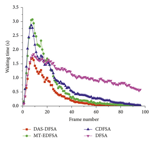
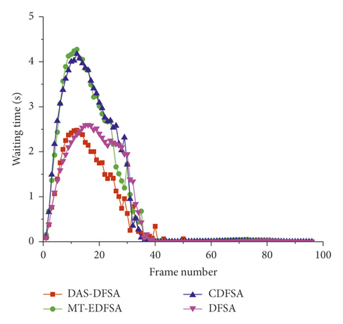
Table 3 gives the specific result values in Figure 9; compared with DFSA, the waiting time of CDFSA, MT-EDFSA, and DAS-DFSA can be reduced by 35.953%, 40.633%, and 67.080%, respectively. Moreover, compared with MT-EDFSA and CDFSA algorithms, the DAS-DFSA algorithm shortens the waiting time of 44.548% and 48.599%, respectively. The average waiting time of the MT-EDFSA algorithm is less than that of the CDFSA algorithm, indicating that the blocking technology has an effect on shortening the waiting time. At the same time, the waiting time of DAS-DFSA algorithm is obviously shorter than that of MT-EDFSA algorithm, indicating that unequal-length slots can also significantly shorten the waiting time. The DAS-DFSA algorithm with the shortest waiting time proves the validity of the above conclusions. More importantly, as shown in Figure 10, the above conclusions are still true when the arrival rate is random, which indicates that the DAS-DFSA algorithm can be applied to different dynamic arrival scenarios at the same time.
5.2. Miss Rate
In dynamic arrival scenarios, the miss rate is an important indicator for evaluating the reliability of the algorithm. The smaller the waiting time threshold, the greater the probability of tag miss. In general, when the miss rate of the algorithm is 0, all tags are guaranteed to be identified and the algorithm is considered to be reliable. In this paper, the observation time range is defined as the duration of each frame. The waiting time threshold should be better to meet the needs of practical applications, such as the speed of the conveyor belt is 3.68 m/s [5], the speed of the highway ETC is 20 km/h, i.e., 5.56 m/s. Hence, the waiting time threshold is 0.5 s and 1.0 s, respectively. Figures 11(a) and 11(b) show the comparison of the miss rate of DAS-DFSA with other similar algorithms under the same threshold. As the above analysis, the miss rate of the threshold of 0.5 s is higher than 1.0 s in Figures 11(a) and 11(b)
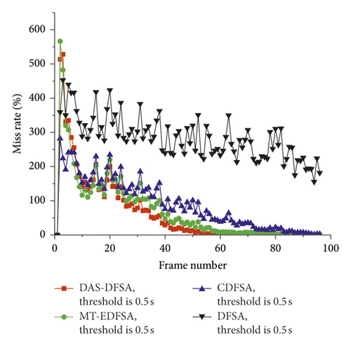
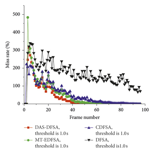
As can been seen from Figure 11, the miss rate of DFSA algorithm cannot tend to 0 under all waiting time thresholds. This is mainly because DFSA cannot immediately identify the new arrival tag at once, resulting in the tag waiting timeout and missed. Conversely, DAS-DFSA, CDFSA, and MT-EDFSA algorithms can identify the new arrival tag immediately, and the waiting time is significantly shortened, decreased by more than 68.140%. More important, as the number of tags decreases, the miss rate of these algorithms can tend to 0, and the reader can implement instant-on-service for new arrival tags without waiting. Hence, there will no tag missed. Obviously, because the DAS-DFSA algorithm optimizes and improves the MT-EDFSA and CDFSA algorithms, compared with the original algorithm, the miss rate is the lowest, decreased by 11.462% and 28.021%, respectively, which proves the validity of the DAS-DFSA algorithm once again.
5.3. Identification Speed
The identification speed is defined as the number of tags identified per second and is used to measure the overall performance of the algorithm, i.e., the service speed of the service station in the queuing theory. In dynamic arrival scenarios, the identification speed is meaningful only when the waiting time and miss rate meet the requirements. Although the faster the identification speed, the better the evaluation must be based on specific operational parameters. According to the parameters given in Table 2, assume that every slot is success slot and the duration of the success slot is 2.7531 ms; then, the maximum identification speed is 363 tags per second. Obviously, this is just an ideal situation. Undoubtedly, through the two important evaluation indicators of waiting time and miss rate, the DFSA algorithm cannot be suitable for the rapid identification of RFID tags in dynamic arrival scenarios. Therefore, we continue to focus on the other three algorithms.
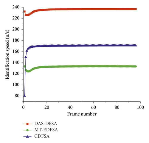
Figure 12 shows the identification speed of the DAS-DFSA, CDFSA, and MT-EDFSA algorithms for tag stable arrival scenarios. The DAS-DFSA algorithm has the fastest identification speed among similar algorithms, and the stability is around 235 per second, which is close to the ideal value of 64.74%. Due to the use of equal-length slots, the MT-EDFSA algorithm takes up longer time in empty slots and collision slots in communication, and the identification speed is the slowest. Although the CDFSA algorithm with unequal-length slot can improve the identification speed, it cannot prevent the collision between waiting tags and the arrival tags. Therefore, the identification speed is significantly lower than that of the DAS-DFSA algorithm. As shown in Table 3, the identification speed of DAS-DFSA is 39.053% faster than that of CDFSA and 78.030% faster than that of MT-EDFSA. Therefore, collision and slot length are both factors affecting identification speed, but the effect of slot length is greater.
5.4. System Efficiency
System efficiency is also one of the key indicators to measure the overall performance of the algorithm. According to the definition of slot-based system efficiency in Section 2.3, system efficiency mainly reflects the proportion of success slots to total slots. Theoretical analysis shows that the maximum system efficiency of the ALOHA-based algorithm is about 0.368 [23]. According to the analysis in Section 5.2, the proposed algorithm can identify the tag without waiting, that is, instant-on-service. Since in the dynamic arrival scenario, even if there is no tag, the algorithm needs to continue to run. If there is no tag in the identification process of a frame, no service is needed at this time. From a mathematical point of view, the system efficiency of the frame is 0. At the same time, from the practical application point of view, it is meaningless to consider the system efficiency of the algorithm at this time. However, from the perspective of facilitating statistical analysis, we set the system efficiency to the theoretical maximum of 0.368 at this time. As shown in Figures 13 and 14, the system efficiency of these algorithms are relatively close under the same arrival rate.
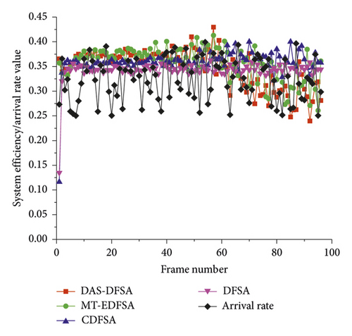
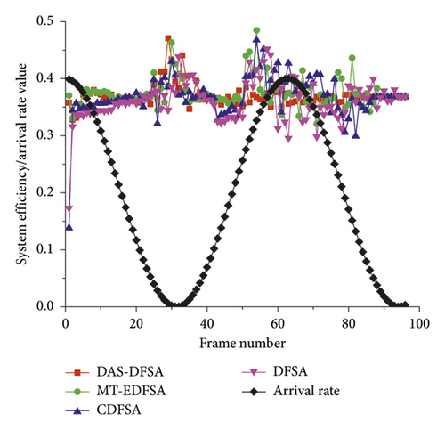
Note that the blocking technology can avoid collisions between new arrival tags and waiting tags, which can improve identification speed and shorten waiting time. However, as the number of unidentified tags in subsequent frame decreases, the frame length is also shortened. At this point, if the shorter frame length is blocked again, the collision will increase and the waiting time will be prolonged. As can be seen from Figure 13, after 60 frames, the system efficiency of the MT-EDFSA and DAS-DFSA algorithms using the blocking technology is lower than the CDFSA algorithm without the blocking technology mainly because the number of tags decreases. On the contrary, in the first 60 frames, because the number of tags is large and the frame length is long enough, blocking technology can prevent collisions and maintain high system efficiency. At this point, the system efficiency of the DAS-DFSA and MT-EDFSA algorithm is higher than the CDFSA algorithm. Overall, the DAS-FSA algorithm can still achieve higher system efficiency.
5.5. Comparison of Different IndicateArrival Transmission Strategies
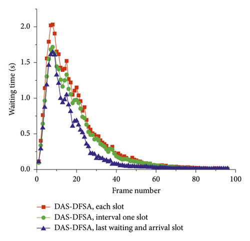
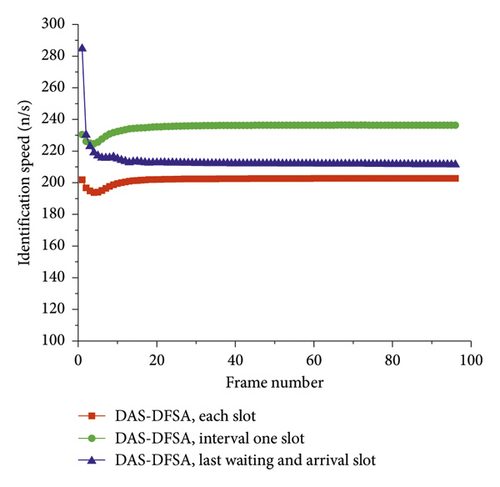
The waiting time includes not only the queuing time but also the communication time for the command delivery. Due to the Indicate instruction includes two different length instructions, that is, IndicateArrival and IndicateWait are 48 bits and 14 bits, respectively. According to Section 4.2, to reduce communication time overhead, the IndicateArrival instruction has three transmission strategies. One is to send the IndicateArrival instruction once in the interval slot, and the other slots send the IndicateWait instruction, named “Interval one slot.” The other is to send the IndicateArrival instruction in the last slot of the waiting process and all slots in the arrival process, and the other slots send the IndicateWait instruction, named “Last waiting and arrival slot.” The last one is to send the IndicateArrival instruction uniformly in each slot, named “Each slot.” Comparison of simulation results for different transmission strategies is shown in Figures 15 and 16.
As described in Section 4.3, both the IndicateWait or IndicateArrival instruction can notify the tag to participate in the identification of this slot, but the state of the tag is different. The IndicateWait instruction is only used to notify waiting tags and arrival tags, whereas other state tags do not respond to it. However, the IndicateArrival instruction notifies all unidentified tags to respond. Undoubtedly, the IndicateArrival instruction is equivalent to opening a subframe in a frame and carrying more parameters. Although the IndicateArrival instruction can replace the IndicateWait instruction, if this instruction is broadcasted at every slot, it takes very long communication time.
Figure 15 shows the results of waiting time when different Indicate instruction transmission strategies are used. The length of IndicateArrival is almost 3.5 times longer than IndicateWait, so the more the IndicateArrival is sent, the longer the communication time is taken. If the IndicateArrival instruction is sent in each slot, it inevitably leads to an increase in communication time and the longest waiting time. If IndicateArrival and IndicateWait are sent alternately, i.e., IndicateArrival is sent in the interval slot, the waiting time will be further reduced. According to the theoretical analysis of blocking technology, new arrival tags only participate in the arrival process. Therefore, if the IndicateArrival instruction is sent only at the last slot of the waiting process and in the arrival process, the waiting time is minimized. This kind of transmission strategy has the most obvious effect on shortening the waiting time. The results of the “Each slot,” “Interval one slot,” and “Last waiting and arrival slot” strategies in Figure 15 prove the above conclusions, respectively.
The different IndicateArrival instruction transmission strategies not only affect the tag’s waiting time but also affects the identification speed. Although the IndicateWait and IndicateArrival instructions have the same function for waiting tags, but the IndicateArrival instruction takes longer communication time, so the more the IndicateArrival instruction is used, the slower the identification speed. Figure 16 shows the results of identification speed when different IndicateArrival instruction transmission strategies are used. If the IndicateArrival instruction is sent in each slot, it inevitably leads to an increase in communication time, and the identification speed is the slowest. If the IndicateArrival instruction is sent at the last slot of the waiting process and all slots in the arrival process, it can shorten the communication time and improve the identification speed, but the effect is not obvious. However, when the IndicateArrival instruction is sent in the interval slot, the communication time is reduced obviously and the identification speed is the fastest. This is mainly because the fewer the slot intervals, the earlier the new arrival tag is identified, so the shorter the waiting time for identification, the faster the identification speed.
6. Conclusions
In this paper, we designed a tag dynamic arrival process model and a tag dynamic identification process model and optimized the frame structure and instruction structure of the communication. Then, we proposed a fast RFID tag anticollision algorithm for dynamic arrival scenarios.
Through optimizing the instruction structure and identification process, the new arrival tag is allowed to participate in the identification of the ongoing frame, which can shorten the tag’s waiting time. Using blocking technology, each frame identification process is divided into a waiting process and an arrival process, to prevent the collision between new arrival tags and waiting tags, so as to improve the system efficiency. In addition, by adopting unequal-length slots, the communication time overhead is further reduced and the identification speed is greatly improved.
Simulation results show that under the same operating conditions, the average waiting time of DAS-DFSA algorithm is reduced by more than 44.548% and the identification speed is improved by at least 39.053% compared with other similar algorithms. In conclusion, the proposed DAS-DFSA algorithm can be applied to the rapid identification of tags in dynamic arrival scenarios of stable arrival and random arrival.
The future work of this paper will continue to study the optimization of the Indicate instruction, frame structure, and blocking strategy of the frame identification process to further improve the performance.
Conflicts of Interest
The authors declare that there are no conflicts of interest regarding the publication of this paper.
Acknowledgments
This work was supported in part by the project of Beijing Key Laboratory of Big Data Technology for Food Safety, Beijing Technology and Business University (BKBD-2017KF10), and in part by National Natural Science Foundation of China (31801669), in part by Key Laboratory of Agricultural Informatization Standardization, Ministry of Agriculture and Rural Affairs (AIS2018-04), and in part by the Chinese Universities Scientific Fund under Grant 2019TC231.
Open Research
Data Availability
The data used to support the findings of this study are included within the article. The data are available from the corresponding author upon request.


