Experimental Investigation of Thermal Modal Characteristics for a Ship’s Foundation under 300°C
Abstract
How to further reduce vibration and noise is a major challenge for modern ship design. High-temperature environment will significantly influence the mechanical properties (such as elastic modulus and stiffness) of the ship’s foundation. These properties will have a serious impact on the inherent vibration characteristics of the foundation. In this paper, a simplified foundation is taken as the research object, and a thermal-vibration joint test system is developed for investigating the thermal modal characteristics of the foundation under different temperatures. The joint test system consists of a transient aerodynamic heating environment simulation system and a vibration excitation and acquisition system. Finite element method (FEM) is used to analyze the distribution of thermal fields. The influence of the ceramic rods and the different ambient temperatures on the modal characteristics of the foundation is studied. The results indicate that the effect of ceramic rods on the modal characteristic of the foundation is negligible. The results also show that the greater the vibration response amplitude is as the temperature increases and the first-order natural frequency does not change, the smaller the second-order natural frequency and the damping ratio will become smaller. The variation of natural frequency and damping ratio of the foundation under different temperature conditions can provide a reliable experimental basis for the design of the vibration and noise reduction of the ship’s foundation in the thermal-vibration environment.
1. Introduction
The foundation of marine equipment is an important part for connecting the equipment and the ship hull. The vibration transmitted by the equipment to the hull can be reduced by the vibration isolation design of the foundation.
The foundation is made of several plates by welding or bonding. The research results of plate vibration reduction can be used as reference in the vibration reduction design of foundation. In recent decades, extensive studies have been carried out on the vibration isolation technology of the foundation. Adding blocking masses [1], using composite foundation [2], and laying viscoelastic damping material [3] are the main methods for vibration reduction of the foundation. The results of the literature review found that the researches of these methods were mainly carried out at room temperature. However, the power density of the modern ship propulsion system is increasing, and the temperature in the power cabin is rising. Especially, the working temperature of related equipment of the nuclear propulsion system can reach 200°C∼300°C. Therefore, the effect of working temperature on the vibration of the foundation should not be neglected.
The methods for constructing a simulated thermal environment are airflow heating and radiant heating. Compared with airflow heating, radiant heating has the advantages of long heating time, strong heating capacity, multitemperature zone control, etc. Therefore, the radiant heating method was widely used in thermostructural experiments [4–6]. Wu et al. [7, 8] designed heating equipment using quartz lamps and established a thermal-vibrational test system for the thermal mode study of the high-temperature resistant composite airfoil structure of hypersonic aircraft under high-temperature environment of 1100°C. Zhang et al. [9] studied the vibration characteristics of sandwich structures composed of fiber composite plates and ceramic foam elastic layers in high-temperature and large gradient thermal environment. Brown [10] performed a theoretical analysis and numerical calculations of the natural frequency and vibration modes of the composite nozzles of an X-34 FASTRAC rocket in a high-temperature environment. Pan et al. [11] used the self-developed transient aerodynamic heating simulation system to study the thermal shielding performance and three-dimensional thermal deformation behavior of two high-temperature alloy honeycomb sandwich panels in a heat-transformed environment. However, in previous researches, most of the thermal-vibrational joint experiments have only been done for simple structures such as flat plates or straight pipelines. Thermal-vibrational joint experiments with complex structures such as equipment foundation have rarely been reported.
In this paper, the high-temperature transient thermal test system and the vibration test system are combined to simulate the thermal-vibrational joint environment of the ship’s foundation. Under the condition of force-thermal coupling, the thermal-vibrational joint experiment of the foundation is carried out, and the variation of the natural vibration characteristics of the equipment foundation under the thermal-vibrational joint environment with temperature is explored, which gives a certain reference value for the stability and reliability design of the ship’s foundation in harsh environments.
2. Experimental Apparatus and Method
2.1. Foundation
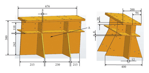
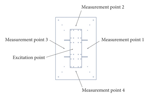
The structural parameters of the foundation are shown in Figure 1. The foundation is made of 45 steel (C45E4). To online monitor the temperature of the foundation, a temperature measuring point is selected at the point A, as shown in Figure 1. The arrangement of excitation point and measurement points is shown in Figure 2. In general, it is enough to get the natural frequencies of the foundation by one acceleration sensor. However, to avoid the influence of temperature nonuniformity on foundation, four measurement points are arranged.
2.2. Experimental System
A thermal-vibration joint test system is developed to investigate the thermal modal characteristics of the foundation. The structural block diagram of the system is shown in Figure 3. This system consists of a transient aerodynamic heating environment simulation system and a vibration excitation and acquisition system. The transient aerodynamic heating environment simulation system is set up for generating the required high-temperature environment. The vibration excitation and acquisition system simulates the external load on the foundation and collects vibration response signals. The two systems complement each other to complete the thermal-vibrational joint test of the foundation.
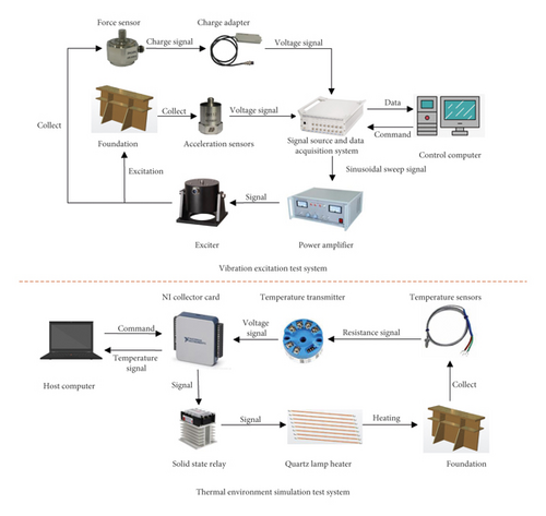
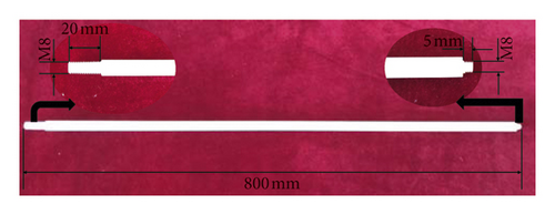
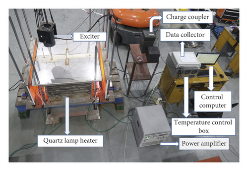
As shown in Figure 4, the foundation is fixed on the T-shaped groove, which is placed horizontally on the ground, through the bolts. The foundation is heated by the quartz lamp infrared heating arrays which are installed on the left and right sides of the foundation. To improve the heating efficiency, two polished plates, which are made of 310S stainless steel and can withstand temperatures up to 1300°C, are used to fix quartz lamps and reflect the quartz light. Furthermore, three aluminum silicate insulation boards are placed in the front/back/top of the foundation to provide heat insulation during heating. The electromagnetic exciter, which is suspended above the foundation by two elastic ropes, is connected with the foundation by a ceramic connected pole. In the thermal modal test, the foundation is excited by the electromagnetic exciter from the outside of the high-temperature environment through a force sensor and a ceramic connected pole. High-temperature acceleration sensors are expensive and require temperature compensation when collecting high-temperature signals. To reduce costs and avoid signal compensation, the acquisition of the vibration signals of the foundation is carried out by ordinary acceleration sensors, which are installed outside the high-temperature environment, through four ceramic rods. The structural parameters of the ceramic rod are shown in Figure 5. Four M8 internal threads, which are 20 mm in length, at the four measuring points on the rib were processed. The ceramic rods are fixed on the four measurement points at one end and connected to the acceleration sensors at another end by threads.

2.3. Generation of the Thermal Environment
2.3.1. Transient Analysis of the Thermal Environment
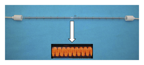
To ensure that the foundation can be heated to the target temperature, two quartz lamp arrays are arranged on the left and right sides of the foundation. As shown in Figure 6, the quartz lamp filament is a single helical structure and is made of carbon fiber heating element [12, 13]. The filament parameters used in this experiment are shown in Table 1:
| Voltage (V) | Power (W) | Filament diameter (mm) | Filament length (mm) |
|---|---|---|---|
| AC 220 | 3000 | 0.45 | 1200 |
The electric heating energy (Q) obtained by the quartz filament as the internal heat source can be calculated according to the energy conservation law as follows:where CP is the specific heat capacity of the filament material, T is the filament temperature, λ is the thermal conductivity, P is the pressure inside the tube, and β is the expansion coefficient.
Whether the thermal field can be heated to the target temperature is determined by the number of quartz lamps. In this investigation, the thermal field was analyzed by the use of the finite element method. To improve the efficiency of the simulation calculation, the three-dimensional model of the thermal environment simulation system is appropriately simplified: the lamp array fixing plate, the aluminum silicate insulation board, and the T-shaped groove are simplified into a flat structure, and all the screw holes on the foundation are removed.
By equivalent (4), 16 quartz lamps can be simplified into 16 equal volume cylinders with a volumetric heat flow of 15370 kW/m2.
The materials used in this simulation process include 310S stainless steel, quartz, 45 steel, and aluminum silicate fibers. Their thermophysical properties are shown in Table 2. To improve the accuracy of the simulation, the temperature-dependent material properties of each material are used in finite element software for calculation. In addition, the emissivity of quartz and stainless steel is 0.9 and 0.8, respectively, and the absorption rates of other materials are set to 0.8.
| Material | Density (kg/m3) | Specific heat capacity (J/(kg · K)) | Thermal conductivity (W/(m · K)) | ||||||
|---|---|---|---|---|---|---|---|---|---|
| 20°C | 20°C | 100°C | 200°C | 300°C | 20°C | 100°C | 200°C | 300°C | |
| 45 | 7824 | 472 | 480 | 498 | 524 | 47.68 | 43.53 | 40.44 | 38.13 |
| 310S | 8030 | 502 | 508 | 517 | 528 | 13.8 | 14.3 | 15.7 | 17.2 |
| Quartz | 2200 | 213 | 213 | 213 | 902 | 3.31 | 3.67 | 3.94 | 4.21 |
| Aluminum silicate | 100 | 900 | 943 | 997 | 1040 | 0.035 | 0.048 | 0.061 | 0.073 |
To simulate the natural convection between air and components, a convective heat transfer coefficient is applied to the surface of each part of the model [14]. The convective heat transfer coefficient of the external surface of the lamp array fixing plate and the aluminum silicate fiberboard are set to15 W/(m2 · K). The convective heat transfer coefficient of the inner surface of the lamp array fixing plate and the aluminum silicate fiberboard and the surface of the foundation are set to 8 W/(m2 · K).
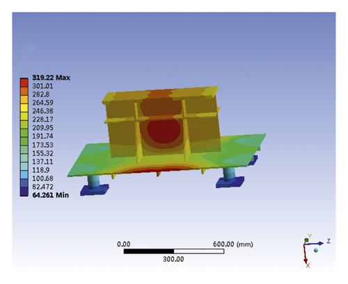
The overall model temperature distribution and foundation temperature distribution obtained by transient thermal analysis are shown in Figure 7. As shown in Figure 7(a), the inner surface temperature of the aluminum silicate fiberboard is close to 300°C, and the outer surface is lower than 100°C. The inner and outer temperatures of the 310S stainless steel plate are relatively similar, and the maximum surface temperature is 485.15°C, which is far lower than its melting point temperature (1300°C). It can be seen from Figure 7(b) that the temperature of the middle part of the upper surface of the foundation rib reaches 320°C, and the other surface temperatures are around 300°C, and the temperature distribution is relatively uniform.

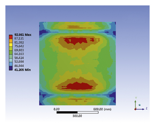
The temperature distribution of the top aluminum silicate fiber thermal insulation board is separately analyzed to ensure the electromagnetic exciter and ordinary acceleration sensors work properly. As shown in Figure 8, the heat of the insulation board is mainly concentrated on both sides of the board, which is near to the quartz lamp arrays, and the temperature in the middle position is lower. The maximum temperature on the insulation board is 92.861°C, which is lower than the safe working temperature of the ordinary acceleration sensors and the electromagnetic exciter.
2.3.2. Experimental Verification of Thermal Environment Simulation System
A self-developed temperature control subsystem based on LabVIEW® is employed to generate the high-temperature environment [15, 16]. The hardware connection is shown in the bottom half of Figure 4. In the thermal modal test, the foundation is heated by two quartz lamp arrays simultaneously, and the temperature of the foundation is collected in real time through the temperature sensor and high-speed data acquisition card. Host computer controls the quartz lamp arrays based on the signal collected through the NI acquisition card and the solid-state relay. Then, the quartz lamp arrays are controlled to turn on and off to keep the temperature of the foundation constant.
In order to verify the correctness of transient thermal analysis in the previous sections, the foundation is heated to 300°C directly. The selection of the temperature measurement point has been described in Figure 2. As shown in Figure 9, there gives a comparison between the actual temperature rise curve and the simulated temperature rise curve. The heating curve can be divided into three stages: start heating, constant heating, and keep temperature. At the start heating stage (temperature <60°C), the lamps are just energized, and the actual temperature of the foundation is 2∼3°C lower than the simulated temperature. At the constant heating stage (60°C∼299°C), the actual temperature rise curve coincides with the simulated temperature rise curve. At the keep temperature stage (target temperature 300°C), the host computer starts to control the on and off of the lamp arrays; therefore, the actual temperature is maintained at about 300°C. But the simulation temperature will rise again because the heat source is constant (not be controlled).

2.4. Vibration Excitation and Acquisition System
As shown in Figure 4, the vibration excitation and acquisition system is composed of four ordinary acceleration sensors, a force sensor, a charge amplifier, a multichannel data acquisition system, controlling computer, a power amplifier, and an electromagnetic exciter. The multichannel data acquisition system is DH5922N dynamic signal acquisition system, which was produced by Donghua Testing Co., Ltd. DH5922N is composed of 32 input channels and 2 output channels. When the system runs, the controlling computer controls the output channel of DH5922N and outputs the sine sweep signal to the power amplifier to generate external stimulus load on the foundation. The external stimulus load is monitored by the force sensor, which is mounted between the exciter output and the excitation rod by means of a threaded connection. The vibration signals of the hull are measured by four ordinary sensors. These vibration response signals are collected in real time by the input channels of the DH5922N, and then, they are sent to the controlling computer for storage and subsequent analysis after processing.
2.5. Analytical Methodology of the Acceleration
In order to study the influence of the effect of equal excitation force on the vibration transmission at different temperatures, the admittance characteristics at each temperature have been analyzed by experiments. The size of the admittance illustrates the ease of structural vibration caused by the same exciting force. The larger the admittance is, the more likely the structural vibration is caused.
2.6. Thermal-Vibration Joint Test Method
Firstly, install the foundation and the thermal-vibration joint test system as mentioned above. Secondly, heat the foundation to the target temperature and maintain the target temperature for 10 minutes. Thirdly, send sine sweep signals to the power amplifier and then drive the electromagnetic exciter to vibrate the foundation. Finally, collect, store, and process the vibration signals of the hull.
2.7. Evaluation Indexes
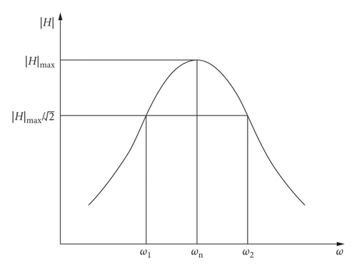
In this investigation, natural frequency (ωn), modal shape, and damping ratio (ξ) are the three thermal modal characteristic parameters of the foundation that we are concerned about.
It can be seen from equation (6) that the natural frequency of the structure is affected by the stiffness distribution and the mass distribution. For the foundation, the temperature will affect the change in stiffness, which in turn causes the structural damping ratio to change.
The panels, webs, brackets, and connecting plates on the foundation are crisscrossed, and the vibration waveforms are transformed, reflected, scattered, and refracted at various joints due to structural abrupt changes. In addition, the structural damping of the foundation also influence propagation of the vibration waveforms which makes vibration sound radiation reduced and vibration energy attenuated [18–20].
3. Thermal-Vibration Joint Test Results and Discussion
3.1. Finite Element Analysis
Before the thermal-vibrational joint test, the finite element method was used to analyze the modal shape of the foundation and the interval between the first-order and second-order natural frequencies of the foundation. These parameters can be determined in advance to provide assistance for subsequent experiments.
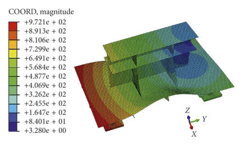
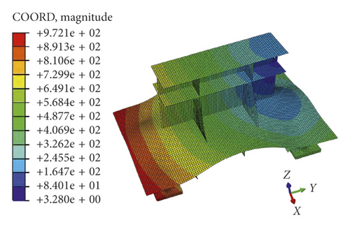
The first-order and second-order modes obtained by modal analysis of the foundation under room temperature are shown in Figure 11. As can be seen from the figure, both the first-order and second-order modal shapes of the foundation are integrally twisted, and their natural frequencies are 90.57 Hz and 337.78 Hz, respectively. Compared with the panel, the web, the connecting plate, and the bracket, the deformation of the rib is the largest, and so, the acceleration value acquired by the acceleration sensor on the rib is the largest. At the same time, a conclusion can be made by the modal analysis of the foundation that the first-order natural frequency of the foundation is about 90 Hz and the second-order natural frequency is about 300 Hz. Therefore, the frequency of the sine sweep signal is set to 50–400 Hz.
3.2. Analysis of the Influence of Ceramic Rods on the Natural Frequency and Damping Ratio of the Foundation
To ensure the accuracy and authenticity of the thermal-vibration joint test data, the influence of the ceramic rod on the modal characteristics of the foundation should be analyzed. Because the acceleration sensors are not high-temperature sensors, the influence of the ceramic rod on the foundation was analyzed only at room temperature (20°C). Before the test started, four acceleration sensors were placed directly on the four measurement points (Figure 2). And then, the foundation was excited by the electromagnetic exciter, and the acceleration signals were recorded by the DH5922N. After the test was completed, the ceramic rods were installed between the acceleration sensors and the four measurement points (foundation). Then, the same excitation force was used to excite the foundation again by the electromagnetic exciter. The acceleration signals were collected and compared with the previous one. As shown in Figure 12, the acceleration value without ceramic rods is greater than that after adding ceramic rods. But the data error of the two tests is less than 5%. Thus, the influence of the ceramic rod on the amplitude of the vibration response can be ignored. At the same time, the difference of natural frequencies between before and after adding ceramic rods is less than 1 Hz.
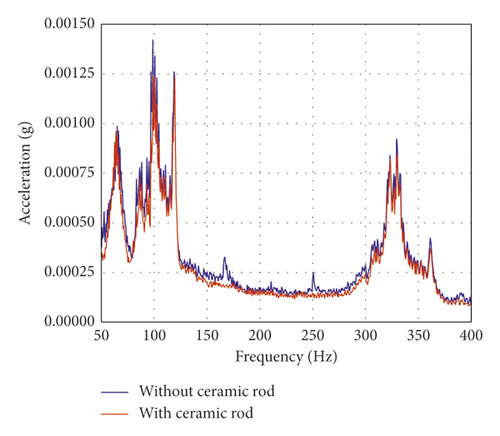
Under room temperature, the damping ratio of the foundation with ceramic rod is 0.0301, and the damping ratio of the foundation without ceramic rod is 0.0308. The deviation of the damping ratio is 2.27%. It means that the influence of the ceramic road on the damping ratio of the foundation can be ignored.
3.3. Experimental Results and Analysis
The layout of the thermal-vibration joint test system for ship’s foundation is shown in Figure 13. To verify the correctness of the finite element analysis, a room temperature test was performed first, and then, the results were compared with the finite element results. The comparison of modal obtained by the test mode and finite element analysis at room temperature are presented in Table 3. It can be seen from the table that the first-order frequency of experimental mode is 9.03% higher than that of finite element mode, and the second-order frequency of experimental mode is 7.32% higher than that of finite element mode. Both of their difference is less than 10%, which indicates that the result of simulation is approximate to that from the practical test.
| First order (Hz) | Second order (Hz) | |
|---|---|---|
| Finite element mode | 90.57 | 337.78 |
| Test mode | 98.75 | 362.5 |
| Deviation | 9.03% | 7.32% |
The amplitude of the excitation force is constant (80 N) during the sine sweeping test. The vibration responses of the foundation under different temperatures are shown in Figure 14. It is obvious that the higher the heating temperature, the greater the corresponding acceleration admittance. At 200°C and 300°C, the first-order natural frequencies of the foundation are similar, but the corresponding acceleration admittance at 300°C is much larger than other operating conditions. At room temperature and 100°C, the first-order natural frequencies of the foundation are similar, and the response acceleration admittance is also approximately the same, but the resonant frequency lags behind the resonant frequencies at 200°C and 300°C. At the second-order natural frequency, the resonant frequency decreases with the increase of temperature. For the second-order mode, the higher the temperature, the greater the acceleration admittance. Comparing the results of finite element modal analysis, the first-order vibration energy at each measurement point is larger than the second-order vibration energy. However, such a phenomenon appeared in the experiment that the first-order response acceleration admittance at measurement point 1 is greater than the second-order response acceleration admittance. The reason for this phenomenon is that the excitation point is not at the center of the panel. The position of the measurement point 1 from the excitation point is farther than that of the measurement point 3 from the excitation point.
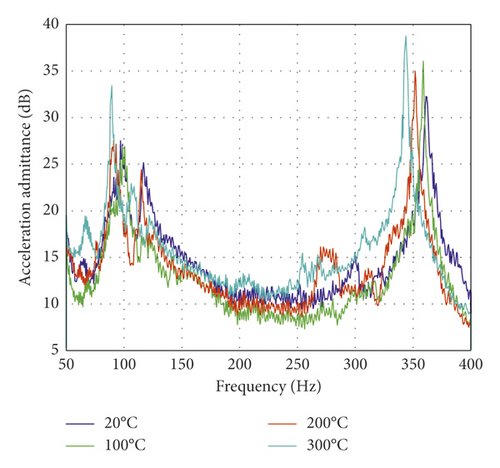
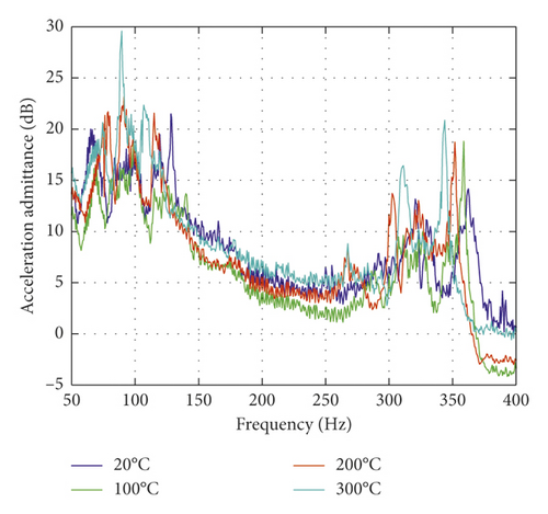

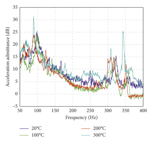
The natural frequency change rates of the foundation at different temperatures are presented in Table 4. It can be seen from the table that, for measurement point 4, the second-order formant only appears under 300°C. According to the previous finite element modal analysis, the amplitude at this point in the second-order modal shape of the foundation is small. The cause of the formant is that the material properties at this point change at 300°C, and the strength and hardness become small, which make the vibration become severe. The change of the first-order natural frequency with temperature is close to the measuring point 3. The rate of change of the first-order and second-order natural frequencies of the measuring point 2 and the measuring point 1 with temperature basically coincides with each other, and both are less than 10%. The influence of the environment temperature of the foundation on the vibration characteristics is mainly due to the change of the mechanical properties of the material and structure due to the high-temperature environment. The elastic modulus and the stiffness of the structure will decrease with the increase of temperature, resulting in the natural frequency of the structure to decrease with increasing temperature.
| Measuring point | Order | 20°C | 100°C | 200°C | 300°C | Rate of change | ||
|---|---|---|---|---|---|---|---|---|
| 1 | First order | 98.75 | 98.75 | 91.25 | 89.375 | 0 | 7.59% | 9.49% |
| Second order | 361.25 | 358.75 | 351.875 | 343.75 | 0.69% | 2.59% | 4.84% | |
| 2 | First order | 98.75 | 98.75 | 91.25 | 89.375 | 0 | 7.59% | 9.49% |
| Second order | 362.5 | 358.75 | 351.875 | 343.75 | −1.03% | 2.93% | 5.17% | |
| 3 | First order | 98.75 | 98.75 | 88.125 | 89.375 | 0 | 10.76% | 9.50% |
| Second order | 321.875 | 316.875 | 314.375 | 308.75 | 1.55% | 2.33% | 4.08% | |
| 4 | First order | 98.75 | 98.75 | 88.125 | 89.375 | 0 | 10.76% | 9.50% |
| Second order | / | / | / | 342.5 | / | / | / | |
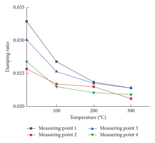
As the energy carried by the foundation when it resonates at the first-order frequency is much larger than that at the second-order frequency, this paper only examines the change of the damping ratio of the overall system which includes the foundation and 4 ceramic rods under different temperature conditions in the first-order frequency resonance. The results are shown in Table 5 and Figure 15. As can be seen from Figure 15, the damping ratios of the measuring point 1 and the measuring point 3 at room temperature are larger than that of the measuring point 2 and the measuring point 4. It can also be seen from Figure 15, with the increase of the temperature, that the gap will become smaller. The damping ratio of each measuring point decreases with the increase of temperature. The reason is that with the increase of temperature, the stiffness of the foundation decrease gradually, and each plate exhibits a softening tendency, so that the dissipation of the excitation energy is reduced on the foundation.
| Measuring point | 20°C | 100°C | 200°C | 300°C |
|---|---|---|---|---|
| 1 | 0.0329 | 0.0268 | 0.0237 | 0.0228 |
| 2 | 0.0257 | 0.0234 | 0.0230 | 0.0212 |
| 3 | 0.0301 | 0.0253 | 0.0235 | 0.0228 |
| 4 | 0.0268 | 0.0230 | 0.0221 | 0.0218 |
4. Results
- (1)
The high-temperature control system can ensure that the temperature of the foundation rises to 300°C, and the temperature rise curve is highly fitted to the transient thermal simulation.
- (2)
The foundation mode obtained by finite element analysis is in good agreement with the experimental mode. It can be seen from the finite element mode that when the foundation panel is excited, the maximum value of response acceleration appears on the rib plate, and the deformation on the rib plate is the largest.
- (3)
The effect of temperature on the vibration characteristics of the foundation is mainly manifested by changes in the natural frequency and damping ratio. For the natural frequency, as the temperature increases, the first-order natural frequency and the second-order natural frequency advance, and the response acceleration admittance increases. For the damping ratio, as the temperature increases, the damping ratio of the foundation decreases first and then stabilizes, but the overall trend is downward.
The thermal modal performance parameters of the ship’s foundation obtained by the thermal-vibrational joint test system provide a reference for the vibration reduction design of the ship’s foundation in the high-temperature environment.
Conflicts of Interest
The authors declare that there are no conflicts of interest.
Acknowledgments
This work was supported by the National Natural Science Foundation of China (grant number 51805086).
Open Research
Data Availability
The data used to support the findings of this study are available from the corresponding author upon request.


