Dynamic Parameter Optimization and Experimental Study of Tuned Slab Damper on Metro Systems
Abstract
With the increase of axle weight and speed, the interaction between vehicles and the track becomes more and more intense, and the problem of wheel-rail dynamic action is more serious. In order to reduce the low-frequency vibration caused by train operation, a three-layer elastic track damping structure is proposed. The complex method is used to optimize the dynamic parameters, structural patterns, and coupling relations of the track structure, which allows multiple elastic units to work in harmony with each other to achieve the effects of absorbing vibration energy and reducing vibration transmission. Finally, a real size model experimental platform is set up to verify the dynamic parameter optimization results. The results show that the vertical mode of the main track system of the coupling-tuned slab damper-floating slab is 26.898 Hz close to the train excitation frequency, and the corresponding equivalent mass is 6074.53 kg. The amplitude of the vibration components in the 20∼40 Hz band can be reduced to 41.8% by using the complex method. The maximum insertion loss is about 10 dB, and the vibration of low-frequency band is not amplified.
1. Introduction
With its advantages of safety, punctuality, comfort, and large capacity, rail transit has become the first choice for citizens to travel [1]. With the increase of axle weight and speed, the interaction between vehicle and track becomes more and more intense, and the problem of wheel-rail dynamic action is more serious [2–5]. In order to solve this problem, many researchers have done a lot of research on the dynamic characteristics and vibration reduction measures of the track structure. Wilson et al. [6–8] put forward the method of floating board and optimizing the structure of vehicle bogie to reduce the dynamic interaction between wheel and rail and reduce the vibration and noise caused by train operation. Cui and Chew [9] conducted finite element modeling of a floating slab track system and analyzed its dynamic characteristics, and the floating slab track can effectively reduce the vibration of frequency band above 15 Hz. The numerical simulation calculation and field test results of Hui and Ng [10] showed that the vibration reduction of 63∼200 Hz band of a rubber floating slab track system could reach 30 dB. Zhao and Wang [11] conducted a field experimental study on the ballastless track system of a vibration-reducing rubber pad. The results showed that the vibration of steel rail and track bed plate increased after the rubber pad was laid, while the vibration of bridge and ground decreased significantly. According to relevant experimental studies [12, 13], the natural frequency of the thoracic and abdominal system is 3∼6 Hz, and the natural frequency of the head-neck system is 20∼30 Hz. For the vibration of the same frequency, acceleration RMS enhances the damage. The longer the body is exposed to the environment of vibration and noise, the greater the damage. Liu et al. [14] pointed out that the low-frequency vibration has become a prime problem for the influences for high-precision instruments and equipment and ancient buildings. Wolf [15] and Ding [16] showed that the floating slab track structure, tunnel structure, and surrounding soils can effectively suppress the high-frequency component and the low-frequency vibration component inhibiting effect is not very obvious. Although some achievements have been made in previous studies, the vibration-reducing track structure can only reduce the vibration of the vibration section with the natural frequency greater than times, and amplify the vibration in the resonance region, which greatly affects the application effect of vibration reduction measures of a floating plate.
To reduce the low-frequency vibration in track engineering, this paper proposes a three-layer elastic track structure of a coupling-tuned slab damper-floating plate. Using the dynamic vibration absorbing principle, a kind of passive damping vibration plate (tuned slab damper) is designed and it can further absorb and consume 20–40 Hz frequency vibration energy and then achieve a better damping track vibration damping effect. By reasonably designing the dynamic parameters, structural patterns, and coupling relations of the tuned slab damper, multiple units work in coordination with each other. The effects of absorbing vibration energy and reducing vibration transmission can be achieved, and the problem of amplification of low-frequency vibration can be reduced. Finally, the full-size track experiment is adopted to verify the dynamic parameter optimization results of the resonator plate.
2. Track Structural Pattern and Theoretical Analysis Model
2.1. Track Structural Pattern
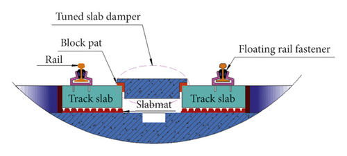
It is shown that the vibration attenuation of a specific frequency band can be achieved by the reasonable design of a dynamic vibration absorber on the basis of a floating slab track [4, 17–19]. Based on this idea, a floating slab track structure with an additional tuned slab damper is proposed to control the vibration of a specific low-frequency band. The tuned slab damper is arranged on the main system of the track structure with the elastic unit, forming an additional mass-spring-damped structure [20], whose structure is shown in Figure 1.
- (1)
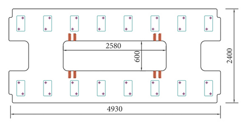
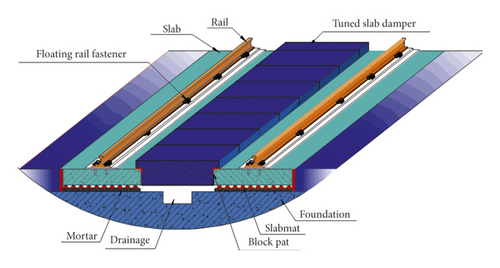
Floating track slab. In order to meet the requirements of on-site construction and in-service maintenance, the track structure is designed into the type of a precast concrete track slab with the length 4.93 m, breadth 2.40 m, and thickness 0.2 m. The middle part of the rail plate is open, and the size of the hole is 0.6 m × 2.58 m. The material is C40 concrete. The track board adopts the two-way prestressed concrete frame board. The precast track board is transported to the project site and spliced into solid track structure. The structure of the precast rail plate is shown in Figure 2.
- (2)
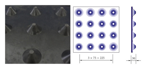
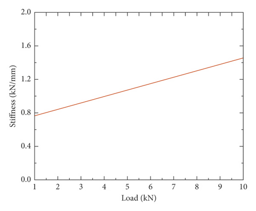
The elastic element under track slab. The force state of the joint between point and surface can be achieved by using the rubber shock absorber cushion of the multilayer bottom plate and the conical nail column structure with obvious damping characteristics, as shown in Figure 3(a). The thickness of the rubber shock absorber cushion is 30 mm, and the surface stiffness is 0.018 N/mm3. The rubber shock absorber pad takes advantage of this unique layer nail structure. In the process of train movement, as the vehicle load increases, the stiffness of the track shock absorber pad increases, which has the characteristics of “low load, low stiffness, high load, and high stiffness,” which not only realizes the effect of vibration reduction but also guarantees the safety of train operation. Once the load is too heavy, the rubber shock absorber only produces small displacement to ensure the smooth running of the train. The structural type and load-stiffness curve of the rubber shock absorber under the plate is shown in Figure 3(b).
- (3)
Rail and elastic fastener. The rail adopts the designation without a bolt hole, which is welded to a seamless pattern on-site. The fastener adopts the floating rail fastener with the vertical stiffness 8 kN/mm, and the spacing of the fastener 0.625 m, and 8 sets of fastener are arranged symmetrically for the inner and outer rails of each precast rail plate. Combined with the design principle of vibration isolator and dynamic vibration absorber, the steel rails are held in place and suspended by rubber bars at the waist of the special rail. And this type of structure can not only realize the isolation of rail vibration but also provide very low vertical stiffness. As shown in Figure 4, the quality unit of the resonant floating rail coupler is embedded into the rubber wedge to form a mass-spring-damped structure so that the vibration energy of the rail can be absorbed by the tuned mass unit, and thus achieving effective control over vibration noise of the rail.
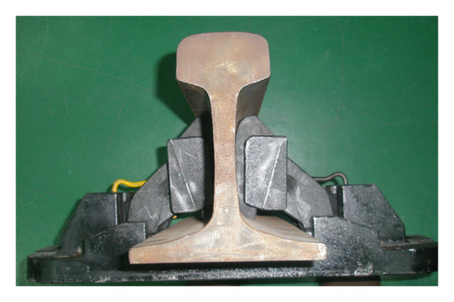
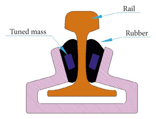
As the effects of reducing vibration of multiple tuned slab dampers installed in parallel on the main system of track structure are usually much better than a single one [17], by combining site construction conditions and technical requirements of prefabricated block assembly, the three-layer elastic track of the coupling-resonant-plate-floating plate is designed as shown in Figure 5.
2.2. Theoretical Analysis Model
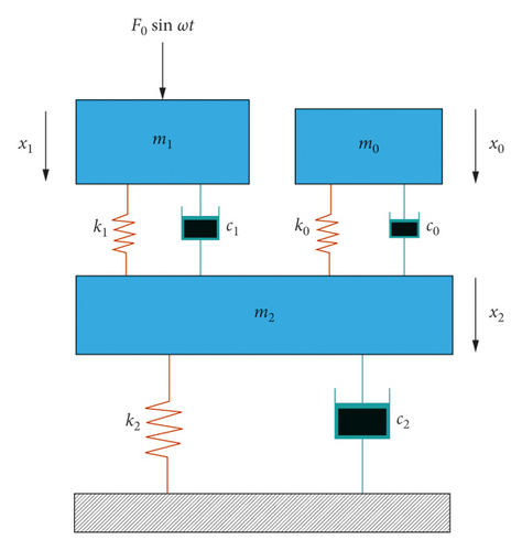
When sufficient consideration is given to the damping of fasteners, the rail structure can be simplified as a three-layer mass-spring-damped structure, as shown in Figure 1, in which the rail is mounted on the floating plate rail by means of fasteners. The rail mass is denoted by m1, and the stiffness and the damping ratio of fastener are represented by k1 and c1. The floating rail plate is fixedly connected with the ballast base through elastic elements. The mass of the floating panel is m2, and the stiffness and the damping ratio of elastic unit are represented by k2 and c2. The additional dynamic resonator plate is fixed on the floating rail plate through the elastic unit. Additional passive mass is denoted by m0, and the stiffness and the damping ratio of fastener are represented by k0 and c0, as shown in Figure 6.
According to the above formula, unknown parameters X10, X20, X11, X21, X12, and X22 in equation (2) can be solved. Since the unknown parameter cannot be all 0, the determinant of the coefficient is zero, i.e., |A| = 0. This equation constitutes a higher-order equation with regard to ω, and its first-order frequency can be obtained by numerical solution; the frequency ratio is defined according to the ratio of the external force frequency to the first-order free vibration frequency γ = (ω/ω1).
3. Modal Analysis of Rail Systems
Using the finite element software Abaqus, the natural frequency and mode of the model of the main system of the track structure are analyzed, which provides the basis for the dynamic parameter optimization of the tuned slab damper.
3.1. Finite Element Model
- (1)
The rail plate and the rail are the main objects of analysis, the elastic fastener is the connection part between the rail plate and the rail, and the rubber damping pad is the main boundary connection unit of the rail plate.
- (2)
The rail plate is a frame-type cement concrete structure. In the main system, there are 5 track plates, which are modeled by solid units.
- (3)
The rail is simulated by using beam element, and its section is simplified to the equivalent section of type I. In this model, rail length 25 m is selected, and 80 sets of fasteners are installed in the range of two rail lengths. The vertical stiffness of the fastener is 8 kN/mm. The spring element (spring 2) with certain stiffness is defined to simulate, and the spacing between the fasteners is 0.625 m.
- (4)
Vibration damping pads thickness is 30 mm, and the surface stiffness is 0.018 N/mm3. It is simplified as a set of spring units with fixed stiffness (spring 1). According to the area of the shock absorber pad and the number of nodes between the track plate and the shock absorber pad and according to the proportion of the stiffness distribution of 1 : 2 : 3 : 4, the stiffness of the convex angle node, boundary point, concave angle node, and inner node is determined so that the total stiffness of the spring unit is equal to the stiffness of the shock absorber pad. The spring units of each rail plate are 2,406.
- (5)
As the track foundation is not the main object of the study, its deformation is not considered, and it is treated as a rigid body. The spring element of the simulated vibration damping pad is a ground spring. The connection plate is set between the rail plate, and the interaction between the connection plate and the rail plate is simulated using tie connection.
According to the above simplification, the finite element model of the track plate system is established, as shown in Figure 7.

3.2. Parameter Setting
The rail board is made from cement concrete with a strength grade of C40, density 2500 kg/m3, elastic modulus 32.5 GPa, and Poisson’s ratio 0.2. The element type is chosen to be C3D8R, with the average length controlled to be 50 mm. There are 9904 elements in each rail plate.
- (1)
The density of the steel rail is 60 kg/m. The material is also steel. The element type is B31, with the length 62.5 mm. There are 400 elements in each steel rail.
- (2)
The fastener is made of a linear spring unit (spring 2) with the vertical stiffness 8 kN/mm.
- (3)
CA mortar and vibration damping pad adopt the ground spring element (spring 1), and the stiffness of the rubber vibration damping pad is 0.018 N/mm3.
The selection of the above unit sizes was verified by grid convergence, the computational efficiency was improved as much as possible on the premise of ensuring the model convergence, and the validity of the finite element model for modal analysis of the track plate system was verified.
3.3. Natural Frequency and Mode of Vibration
Modal analysis within the frequency range of the above vibration-reducing track plate system was carried out to extract the first 60 modes, and the order and natural frequency of each mode are shown in Table 1.
| Order | Natural frequency (Hz) |
|---|---|
| 1 | 16.108 |
| 2 | 16.108 |
| 3 | 25.866 |
| 4 | 26.645 |
| 5 | 26.898 |
| 6 | 26.980 |
| 7 | 27.274 |
| 8 | 27.960 |
| 9 | 28.280 |
| 10 | 29.925 |
| 11 | 30.075 |
| 12 | 30.367 |
| 13 | 30.763 |
| 14 | 31.287 |
| 15 | 31.563 |
| 16 | 32.224 |
| 17 | 32.225 |
| 18 | 32.429 |
| 19 | 33.478 |
| 20 | 33.993 |
| 21 | 36.907 |
| 22 | 37.234 |
| 23 | 39.202 |
| 24 | 41.142 |
| 25 | 41.782 |
| 26 | 43.623 |
| 27 | 45.787 |
| 28 | 45.863 |
| 29 | 48.357 |
| 30 | 48.357 |
| 31 | 48.943 |
| 32 | 50.414 |
| 33 | 52.323 |
| 34 | 55.388 |
| 35 | 59.220 |
| 36 | 62.131 |
| 37 | 63.523 |
| 38 | 64.512 |
| 39 | 64.514 |
| 40 | 66.549 |
| 41 | 69.856 |
| 42 | 71.393 |
| 43 | 72.671 |
| 44 | 73.993 |
| 45 | 74.796 |
| 46 | 78.136 |
| 47 | 79.458 |
| 48 | 79.877 |
| 49 | 80.697 |
| 50 | 80.699 |
| 51 | 81.451 |
| 52 | 81.666 |
| 53 | 81.997 |
| 54 | 82.147 |
| 55 | 82.298 |
| 56 | 82.603 |
| 57 | 82.946 |
| 58 | 83.338 |
| 59 | 84.578 |
| 60 | 84.608 |
As the excitation of the rail system is mainly in the vertical direction, it can be seen from the modal shape that some of the first 50 modes are not in the vertical mode. The typical vertical mode is selected, as shown in Figure 8, where the vertical vibration frequency of the system is 26.898 Hz.
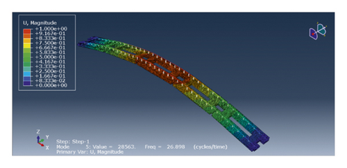
The mass induction method is easy to be affected by the coupling effect between modes, and the calculated equivalent mass contains error. It is necessary to use different additional mass for modal mass identification to eliminate the effect of modal coupling. Therefore, by using the least square curve fitting, the magnitude and equivalent mass of the added mass were taken as the horizontal and vertical axes, respectively, and the equivalent mass of the added mass was obtained when the added mass was zero, that is, the mass in this mode.
According to the above analysis, the vertical mode (26.898 Hz) of the track plate is close to the train excitation frequency (32.4 Hz). When optimizing the dynamic parameters of the resonator plate, it should be designed according to the mode. At the same time, the equivalent mass corresponding to the vertical mode can be calculated as M = 6074.53 kg in the finite element software.
4. Dynamic Parameter Optimization of Resonator Plate
In order to achieve the effect of absorbing vibration energy and reducing vibration transfer and to give full play to the elastic stiffness and damping characteristics, the complex method in structural optimization design is adopted to optimize the dynamic parameters of the resonator plate.
4.1. Complex Method Optimization Method
The complex method [22] is a tuning method that only relies on the function value to predict the possible problem and is a numerical optimization algorithm with strong applicability. The basic idea is to construct k complex vertices in the feasible region of design space. The values of the vertex functions are arranged according to the size, and the best and worst points of the function values are found. The tuning direction and the length are determined by combining the linear reflection worst points with the one-dimensional search method. In this way, the complex vertex is adjusted continuously so that the region contained by the complex becomes smaller and smaller, and the solution of the problem gradually converges to the local optimal solution. The algorithm steps of the complex method include the following steps:
Step 1 (determine the initial feasible points). In the primary domain of the problem, random k design points are generated by the computer for an integer within the n-dimensional space that satisfies k ≥ n + 1.
Step 2 (form the initial complex). In the construction process of the complex method, all points are required to be feasible; that is, all k points generated randomly should meet all m constraints:
Through step 1, it is impossible to ensure that all k alternative points are feasible, so all k alternative points need to be tested for availability. If there are p points satisfying the constraint, and k − p vertices do not satisfy the constraint, then the midpoint of p vertices should be first evaluated and represented by subscript c, i.e.,
And then k − p vertexes that do not satisfy the constraint approach the point , that is,
If the test point meets the constraint condition, increase the value s to make it closer to the point until the constraint condition is satisfied.
Step 3 (sort the function values). Calculate the value of the function corresponding to the available k design points, and arrange them in the order of size. Let the best point be denoted as Xg, the worst point be denoted as Xb, and the second bad point be denoted as Xs, then
Step 4 (calculate the reflection base point). The geometric center of the rest complex vertex is calculated according to the formula below, which is used as the base point of the reflection worst point:
At the same time, judge the availability of , if not available, Xg is taken as the first vertex, re-select the initial complex, and go to step 2.
Step 5 (tune the search). Let us find the reflection point
If the point Xr is not available, cut α into half until the point Xr is available. Then, compare F(Xα) with the best point F(Xg).
Step 6 (convergence check). The convergence and termination criteria of the complex method can be determined according to formula (18). Formula (1) indicates that the complex size is small enough, while formula (2) indicates that the value of the complex vertex function is very close; that is, the design point is very close to the local advantages of the problem:
4.2. Optimization Process and Results
4.2.1. Variables and Constraints
The normal running speed of subway vehicles is about 45–90 km/h, formula of excitation load frequency caused by discontinuous support of the wheel through the fastener f = v/(3.6 × L) where L is distance between fasteners. According to the formula, the main frequency range of excitation caused by wheels through couplers is 20–40 Hz, which is then optimized for vibration of this frequency band.
For the track structure model of the coupler-tuned slab damper-floating plate, using μ0 = m0/m2, λ0 = c0/c2, η0 = k0/k2 as variables of optimization, the target function is selected as and , which have been derived from equations (7) and (8). On the basis of the analysis process of the vibration-reducing track model, the value of the objective function can be obtained by numerical calculation after using MATHEMATICA software programming.
The parameters of rail and rail plate are taken as m1 = 295.8 kg, m2 = 6074.53 kg, c1 = 50 × 103 kN · s/m, c2 = 25 × 104 kN · s/m, k1 = 3 × 10⁷ N/m, k2 = 2 × 10⁸ N/m and the variable constraints are set to be 0 < μ0 < 0.5, 0.1 < λ0 < 1, 0.1 < η0 < 1. In order to enhance the effect of vibration reduction in the low-frequency region, the vertex of the frequency curve must fall in the interval 20 Hz < (2π/ω) < 40 Hz.
4.2.2. Convergence Criteria
For the j calculation, there is the best point , the worst point , and the convergence would be achieved when .
4.2.3. Form the Initial Complex
First, the pseudorandom numbers that meet the interval μ0, λ0, η0 are generated, as shown in Table 2.
| No. | μ0 | λ0 | η0 | βs | βf |
|---|---|---|---|---|---|
| 1 | 0.24043 | 0.03615 | 0.48566 | 1.6270 | 6.6206 |
| 2 | 0.05969 | 0.39614 | 0.04107 | 1.7181 | 5.4342 |
| 3 | 0.46476 | 0.37679 | 0.35903 | 1.3695 | 4.5112 |
| 4 | 0.47287 | 0.22507 | 0.96574 | 1.6140 | 6.8315 |
4.2.4. Calculation Process and Results
Table 3 can be obtained according to the complex method optimization process mentioned above.
| No. | Number of iterations | Complex vertex | βs | βf | Coefficient value of successful tuning | Replacement | |||||
|---|---|---|---|---|---|---|---|---|---|---|---|
| μ0 | λ0 | η0 | α | β | γ | ||||||
| 1 | 0 | 0.24043 | 0.03615 | 0.48566 | 1.6270 | 6.6206 | Initial complex | ╳ | |||
| 2 | 0 | 0.05969 | 0.39614 | 0.04107 | 1.7181 | 5.4342 | ╳ | ||||
| 3 | 0 | 0.46476 | 0.37679 | 0.35903 | 1.3695 | 4.5112 | ╳ | ||||
| 4 | 0 | 0.47287 | 0.22507 | 0.96574 | 1.6140 | 6.8315 | ╳ | ||||
| 5 | 1 | 0.21247 | 0.27839 | 0.16451 | 1.3818 | 3.4291 | 0.1625 | 1.2 | 5-4 | ╳ | |
| 6 | 2 | 0.24615 | 0.38108 | 0.15920 | 1.3439 | 2.8434 | 0.0812 | 1.2 | 6-1 | ╳ | |
| 7 | 3 | 0.34811 | 0.33718 | 0.25789 | 1.3486 | 3.8168 | 0.1625 | 7-2 | ╳ | ||
| 8 | 4 | 0.14161 | 0.30324 | 0.08651 | 1.4339 | 2.9800 | 0.6500 | 8-3 | ╳ | ||
| 9 | 5 | 0.15197 | 0.31561 | 0.09737 | 1.4239 | 2.9872 | 0.3250 | 9-7 | ╳ | ||
| 10 | 6 | 0.17674 | 0.33866 | 0.10947 | 1.3858 | 2.8007 | 0.0812 | 1.2 | 10-5 | ╳ | |
| 11 | 7 | 0.24463 | 0.38059 | 0.15120 | 1.3358 | 2.7293 | 1.3000 | 1.2 | 11-9 | ╳ | |
| 12 | 8 | 0.22908 | 0.37194 | 0.14430 | 1.3475 | 2.7663 | 0.0812 | 12-8 | ╳ | ||
| 13 | 9 | 0.21443 | 0.36232 | 0.13302 | 1.3532 | 2.7329 | 0.0812 | 13-6 | ╳ | ||
| 14 | 10 | 0.23366 | 0.37429 | 0.14555 | 1.3428 | 2.7416 | 0.0812 | 14-10 | ╳ | ||
| 15 | 11 | 0.23376 | 0.37312 | 0.14163 | 1.3370 | 2.6779 | 1.3000 | 1.2 | 15-12 | ╳ | |
| 16 | 12 | 0.22670 | 0.36845 | 0.13633 | 1.3392 | 2.6607 | 1.3000 | 1.2 | 16-14 | ╳ | |
| 17 | 13 | 0.23838 | 0.37596 | 0.14468 | 1.335 | 2.6835 | 0.1625 | 17-13 | ╳ | ||
| 18 | 14 | 0.21472 | 0.35991 | 0.12478 | 1.3391 | 2.5929 | 1.3000 | 1.2 | 18-11 | ╳ | |
| 19 | 15 | 0.2164 | 0.36144 | 0.12746 | 1.3409 | 2.6197 | 0.6500 | 19-17 | ╳ | ||
| 20 | 16 | 0.20986 | 0.35686 | 0.12165 | 1.3418 | 2.5923 | 0.6500 | 20-15 | ╳ | ||
| 21 | 17 | 0.20857 | 0.35588 | 0.12007 | 1.3411 | 2.5796 | 0.3250 | 1.2 | 21-16 | ╳ | |
| 22 | 18 | 0.20896 | 0.35603 | 0.12010 | 1.3405 | 2.5760 | 0.3250 | 1.2 | 22-19 | ╳ | |
| 23 | 19 | 0.20822 | 0.35566 | 0.11993 | 1.3415 | 2.5811 | 0.1625 | 23-18 | ╳ | ||
| 24 | 20 | 0.20759 | 0.35507 | 0.11877 | 1.3405 | 2.5686 | 0.6500 | 1.2 | 24-20 | ╳ | |
| 25 | 21 | 0.20861 | 0.35566 | 0.11920 | 1.3395 | 2.5649 | 1.3000 | 1.2 | 25-23 | ╳ | |
| 26 | 22 | 0.20810 | 0.35513 | 0.11824 | 1.3385 | 2.5543 | 1.3000 | 1.2 | 26-21 | ╳ | |
| 27 | 23 | 0.20743 | 0.35471 | 0.11767 | 1.3386 | 2.5520 | 0.6500 | 1.2 | 27-22 | ╳ | |
| 28 | 24 | 0.20876 | 0.35532 | 0.11775 | 1.3364 | 2.5391 | 1.3000 | 1.2 | 28-24 | ╳ | |
| 29 | 25 | 0.20730 | 0.35411 | 0.11584 | 1.3353 | 2.5229 | 1.3000 | 1.2 | 29-25 | ||
| 30 | 26 | 0.20765 | 0.35444 | 0.11634 | 1.3356 | 2.5274 | 0.6500 | 30-26 | |||
| 31 | 27 | 0.20798 | 0.35461 | 0.11648 | 1.3353 | 2.5263 | 0.1625 | 31-27 | |||
| 32 | 28 | 0.20746 | 0.35423 | 0.11597 | 1.3353 | 2.5233 | 0.1625 | 32-28 | |||
At this point, the best point is , and the worst point is ; hence, , and the condition of convergence is met. The optimal parameters are μ0 = 0.20730, λ0 = 0.35411, and η0 = 0.11584. The vertex of the frequency curve is 20.156 Hz, which meets requirement.
The extended point theory is used for optimization [12–14], which ignores the effect of the stiffness of the fastener, the damping of the fastener, and the damping of the rail plate (ξ2 ≤ 5%); the other parameters are the same. When μ = 0.20730, we get m0 = 1259.3 kg,c0 = 96049 N · s/m, and k0 = 2.8445 × 10⁷N/m, the results of the two optimization methods are compared as shown in Figure 9.
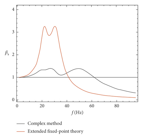
It is shown that the amplitude of βs is reduced from 3.35 of extended point theory to about 1.40 of the complex method on the band of 20 ~ 40 Hz, namely, the vibration amplitude reduced to 41.8% of the previous value.
5. Model Experiment
According to the requirements of actual track design, the full-size model track test platform with 25 meter long is built. The influence of the tuned slab damper on track dynamic characteristics is studied by comparing the experimental data.
5.1. Experimental System
- (1)
The multilayer elastic parts track system is composed of steel rails, damping fastener, prestressed track plate, ballast vibration isolation pads, dynamic resonance plate, base foundation, and other components. The track structure is assembled by prestressed track plate, each track plate has a length of 4.93 m, width of 2.4 m, and thickness of 0.2 m, with holes in the middle. The track plate material is C40 concrete, and the prestressed track plate adopts two-way prestressed concrete frame structure. The test platform is made up of 5 track boards with a total length of about 25 m.
- (2)
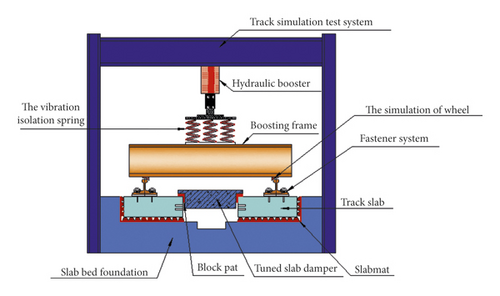
The preloading system consists of a reaction frame, hydraulic jack, augmentation frame, and analog wheel.
- (3)
The signal acquisition device mainly consists of dynamic signal acquisition instrument, signal analysis software, displacement sensor, and acceleration sensor.
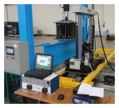
The test system is shown in Figure 10.
5.2. Experimental Method
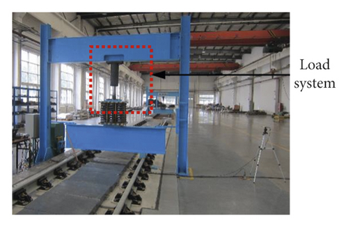
The test system divides the action of the vehicle on the track structure during operation into two forms, namely, quasi-static load and dynamic load. The quasi-static load is realized by the hydraulic loading system, reaction frame, and analog wheel, and the gravity effect of vehicle is simulated by preload. Dynamic loads are achieved by the falling hammer to simulate the impact of the vehicle on the track structure. In order to eliminate the propagation of track vibration signals to track foundation through the loading excitation system and reduce the influence of loading system on track coupling and additional constraints, a decoupling isolation device is designed between quasi-static loading system and afterburner. The quasi-static loading system is shown in Figure 11.
In order to study the influence of the vibration absorbing plate on track dynamic characteristics and test the effect of vibration reduction after optimization, the drop hammer test is carried out on the track with or without vibration absorbing plate, and the test is carried out under the condition of preloading. The drop hammer experiment is carried out with a special drop hammer tester. The sensor is installed at the measuring point as required, and then the drop hammer impact experiment is conducted on the rail, as shown in Figure 12. In the experiment, a weight of 50 kg the drop hammer falls from 100 mm, and the vibration acceleration response of the resonator plate and the track foundation is measured and the collected signal is analyzed by 1/3 frequency range [23, 24]. Experimental data are collected by the data acquisition system, which is composed of scxi-1000 and scxi-1531 hardware produced by NATIONAL INSTRUMENT manufacturer, vibration acceleration sensor produced by PCB factory, etc. The acceleration sensor is arranged in the loading section, and the specific position is rail, track plate, and track foundation. After each adjustment of working conditions, 6 preshocks were made before the formal experiment. In each working condition, at least 3 times of effective drop hammer impact were carried out, respectively, and data were collected. The mean values of the three times of experimental data were taken as the final measurement results. The analysis frequency range is 1.25 ~ 250 Hz, the vibration accelerometer Z weight is adopted for calculation, and the reference acceleration is 10−6 m/s2; the influence of with/without vibration absorbing plate on the dynamic characteristics of track structure can be compared and studied from the frequency domain perspective [25, 26].

5.3. Experimental Results
During the experiment, the hammer punch can move along the track, and the hammer strike point was set on the rail directly above the fastener and the rail between two adjacent fasteners.
5.3.1. Data Analysis of Orbital Foundation
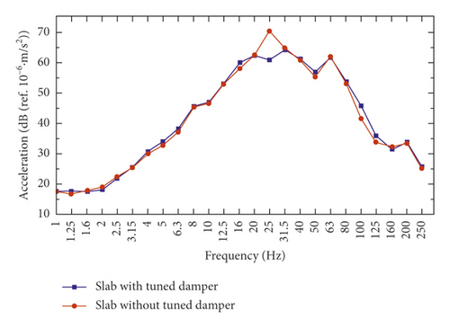
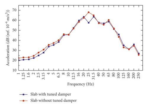
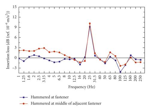
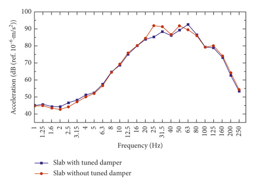
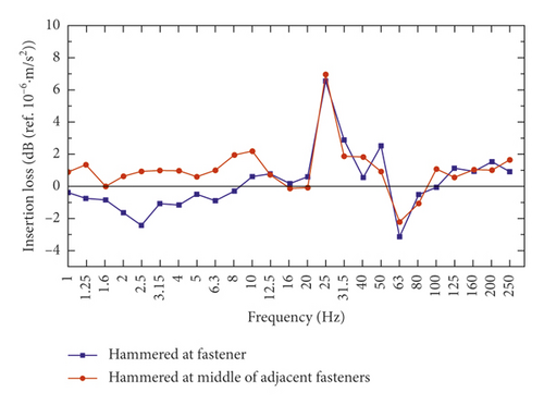
From Figures 13 and 14, under the condition of without vibration absorbing plate, there is the maximum vibration level at 25 Hz for the vibration of track foundation. In contrast, the frequency spectrum data of the system with vibration absorbing plate are significantly smaller than the system without plate in the frequency range of 20 ~ 40 Hz. Figure 15 shows insertion loss at track foundation measurement points is about 10 dB at 25 Hz, and the insertion loss does not change much at the region beyond 20 ~ 40 Hz.
5.3.2. Data Analysis of Vibration Absorbing Plate
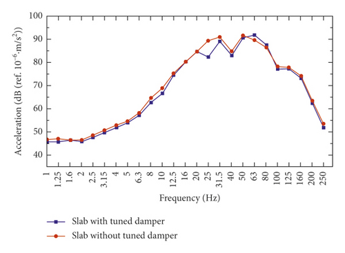
As shown in Figures 16 and 17, under the condition of without vibration absorbing plate, there are two vibration peaks at 25 Hz and 50 Hz. At the frequency range of 20 ~ 50 Hz, the frequency spectrum data with vibration absorbing plate are significantly less than that without vibration absorbing plate. However, the with/without vibration absorbing plate has little effect on the vibration peak at 50 Hz. Figure 18 shows insertion loss at track foundation measurement points is about 8 dB at 25 Hz, and the insertion loss does not change much at the region beyond 20 ~ 50 Hz.
6. Conclusion
- (1)
The analysis model of the three-layer elastic track damping structure is modeled by structural dynamics theory and obtains the analytic solutions of the dynamic control index of orbit under harmonic loads.
- (2)
Model analysis is carried out for the main track system, the vertical mode (26.898 Hz) is close to the excitation frequency, which corresponds to equivalent mass M = 6074.53 kg.
- (3)
Parameter optimization is implemented by the complex method, and the optimal mass ratio of vibration absorbing plate is μ0 = 0.20730. The amplitude of the vibration components in the 20∼40 Hz band can be reduced to 41.8%.
- (4)
Experimental data show that the vibration of the absorbing plate is consumed by the damping property of the elastic element so as to reduce the peak value of track vibration. The maximum insertion loss is about 10 dB, and the vibration of low-frequency band is not amplified.
Conflicts of Interest
The author declares no conflicts of interest.
Acknowledgments
The present work thesis was supported by the creative project of Guangzhou Institute of Measuring and Testing Technology (Grant no. 2017GZIMTT01).
Open Research
Data Availability
The data used to support the findings of this study are available from the corresponding author upon request.


