Fault Tolerant Control of Internal Faults in Wind Turbine: Case Study of Gearbox Efficiency Decrease
Abstract
This paper presents a method to control the rotor speed of wind turbines in presence of gearbox efficiency fault. This kind of faults happens due to lack of lubrication. It affects the dynamic of the principal shaft and thus the rotor speed. The principle of the fault tolerant control is to find a bloc that equalizes the dynamics of the healthy and faulty situations. The effectiveness decrease impacts on not only the dynamics but also the steady state value of the rotor speed. The last reason makes it mandatory to add an integral term on the steady state error to cancel the residual between the measured and operating point rotor speed. The convergence of the method is proven with respect to the rotor parameters and its effectiveness is evaluated through the rotor speed.
1. Introduction
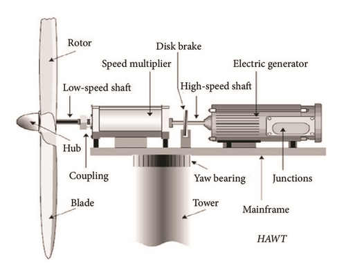
However, the dusty and wet environment induces degradation in some critical components such as the blades, the shafts, the sensors, the generator, and the mechanical components such as the gearbox. Moreover, the challenging situations in which the wind turbines operate (high winds and turbulences, faults on the sensors, and actuators [4]) require highly available systems. For this reason, fault tolerant control strategies [5] are elaborated to prevent the damaging effect of faults and failures on the turbine structure [6]. Most of the FTC methods are composed of two blocs. The first bloc estimates the fault and provides information about the amplitude and the shape of the fault. The last information is then provided to the FTC bloc to build a new control law suitable for the faulty situation. The production of the new control law could be performed either by changing the regulator’s parameters or by adding a new term to the old control law to compensate the fault term. More details on faults in the wind turbines and their FTC could be found in [7], where different types of faults and their corresponding severities are cited. Leakage fault in the hydraulic actuators which is of high severity could not be resolved and the only solution is to shut down the wind turbine for possible maintenance.
In the present paper, the considered fault is the degradation of the efficiency of the gearbox linking the rotor to the generator. It is a fault of medium severity which impacts the dynamics of the rotor and then deteriorates the result of the speed regulation. It will be demonstrated that the fault could be considered an internal fault and a suitable fault tolerant strategy is then applied.
2. The Wind Turbine Model
The considered nominal objective of the wind turbine control is to regulate the rotor speed about the operating value of 40 rpm. The chosen operating wind speed is 18 m/s with 30% of variations according to Kaimal distribution.
The blade pitch operating angle is 9°. This operating point belongs to the high wind region where the only objective is to regulate the power by regulating the rotor speed. This prevents the wind turbine from exceeding the nominal values and from being damaged due to high winds. The parameters of the wind turbine are extracted through linearization from the software FAST [8]. FAST is industrial software developed by the National Renewable Energy Laboratory in Colorado to test and validate the control laws on the wind turbines before physical implementation.
The considered control objective requires considering the rotor and the gearbox models.
2.1. The Rotor Speed Model
2.2. The Gearbox Model
2.3. Aerodynamic Torque Estimation
The aerodynamic torque could be estimated from the drive train model.
2.3.1. Drive Train Model
2.3.2. Torque Estimation Loop
In literature, many approaches have been proposed for aerodynamic torque estimation. Authors in [10] proposed a PI based observer to estimate aerodynamic torque. In [11] authors used the Kalman filter to reconstruct the aerodynamic torque Fourier coefficients. In this paper, the proposed method is based on the transfer function between the aerodynamic torque Ta and the rotor speed Ωr. However, in most cases, the rotor speed cannot be measured; the measured generator speed about low speed shaft could be considered as a good approximation to the rotor speed. In fact, after transients, the rotor and generator speed about the equivalent low speed shaft are the same, in the case of a rigid equivalent shaft, or when damping the torsional modes of the mechanical shaft.
The idea is to keep the model speed Ωgm sufficiently close to the measured one, Ωg, by acting on the model with an adequate aerodynamic torque . This could be performed through a feedback estimation loop as presented in Figure 2. In contrast to authors in the previous works, and since the transfer function F(s) already contains an integrator term, and assuming that the mean of Ωg is sufficiently low frequency, only a proportional action is needed to estimate Ta. After transients, the model output Ωgm converges to Ωg and its input converges to the actual torque Ta. Finally, can be considered as an estimation of the actual aerodynamic torque Ta. The proportional torque estimator gain is chosen in such way that the slowest pole of the closed loop of the transfer function F(s) is cancelled.
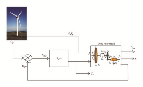
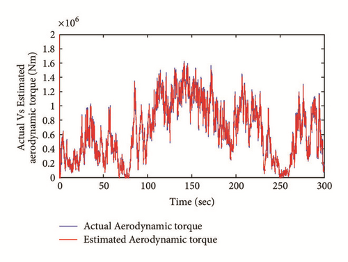
Note that KpTr is the proportional torque estimator gain; ErΩg is the speed tracking error, Tg is the generator torque about the high-speed shaft, Ng is the gearbox ratio, and the term NgTg is the generator torque about the low speed shaft; Ωgm is the model generator speed about low speed shaft; Ωg is the measured generator speed; X is the restoring force of the low speed shaft; Ωrm is the model rotor speed; is the estimated aerodynamic torque.
2.4. Estimated Aerodynamic Torque Filtering
In this section, a spectral analysis is performed to identify the frequencies of the wind speed transmitted to the torque and those resulting from the mechanical vibration. The objective is to reconstruct the frequencies specific to the wind speed. Figures 4 and 5 show the power spectral density of the wind profile and aerodynamic torque, respectively.
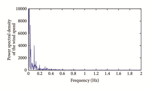
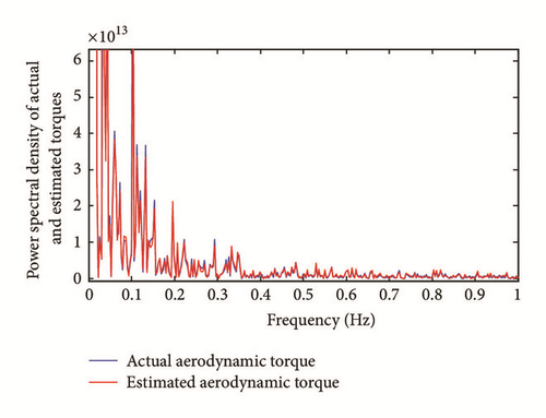
One can notice that the frequencies contained in the wind and having a significant effect on the torque of the rotor resides in the low frequency range (<0.12 Hz). The peaks that occur beyond this area are the result of vibrations of the mechanical structure as a result of excitations caused by the wind. The estimated aerodynamic torque, which will be used for reconstitution of the wind speed, should therefore be filtered according to the previous remark. In the case of our system, we chose a low pass filter of 0.4 Hz bandwidth. Figure 6 shows the power spectral density of filtered and the nonfiltered torque.
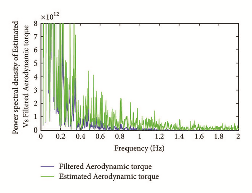
From Figure 6, one can notice that frequencies above 0.4 Hz have been attenuated and filtered.
2.5. Gearbox Efficiency Estimation
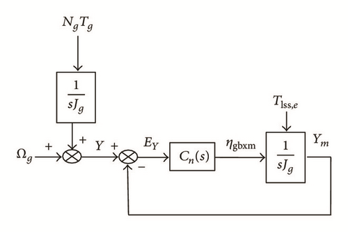
Ωg is the measured generator speed, EY is the tracking error loop, ηgbxm is the estimated drive train efficiency, NgTg is the generator torque about the low speed shaft, and Tlss,e is the previously estimated shaft torque. Y is the measured variable to be tracked by the model’s output. Cn(s) is the proportional action transfer function used for the estimation. Cn(s) is a constant gain M.
In the present case, the proportional gain M is fixed at lower values and progressively increases until we have got good estimation results. For this turbine, we found optimal K at 0.9.
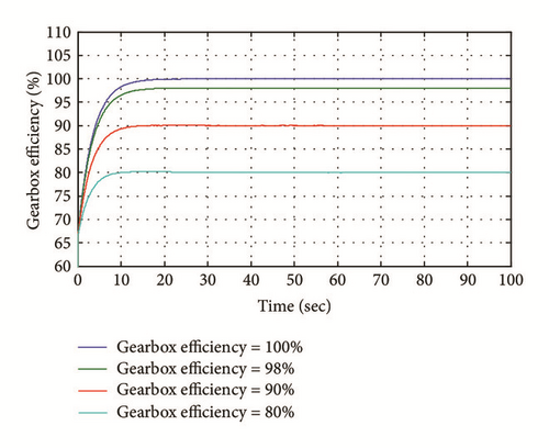
2.6. Gearbox Efficiency Impact on the Eigenvalues of the Dynamic Matrix
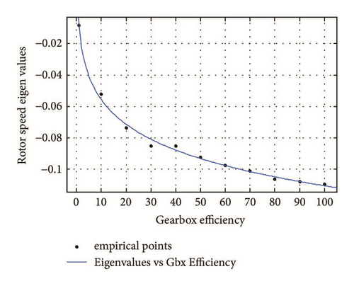
This paragraph shows that the efficiency fault impacts the stability of the system. Hence, the fault tolerant control becomes necessary.
3. The Fault Tolerant Control Strategy
3.1. Dynamics Equalization Gain
3.2. Convergence of the Dynamics Equalization Method
3.3. Steady State Reconfiguration by Residual Integration
3.4. Convergence of the Integrated Strategy
3.5. Robustness Considerations
4. Results and Discussions
Figure 10 illustrates the rotor speed in the nominal, faulty, and fault tolerant cases. In order to evaluate the effectiveness of the method, the distance (according to the ordinates axis) between two points on the curve is considered. The first point is P1 with abscissa 143 seconds and the second point P2 with 90.34 seconds of abscissa. In the nominal situation, the difference between the ordinates of P1 and P2 is of 8.1 rpm; this value becomes 11.5 rpm in the faulty situation. By using the fault tolerant control strategy, this value is reduced to 9.2 rpm. As shown in the same Figure 10, not only the dynamics are impacted but also the steady state value of the rotor speed which become closer to 40 rpm operating point due to the integral term N∫(δΩrf − δΩr) in the control law.
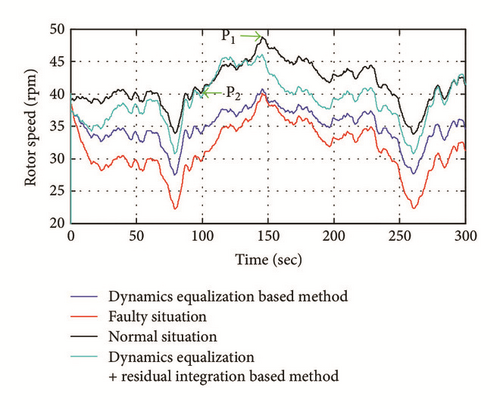
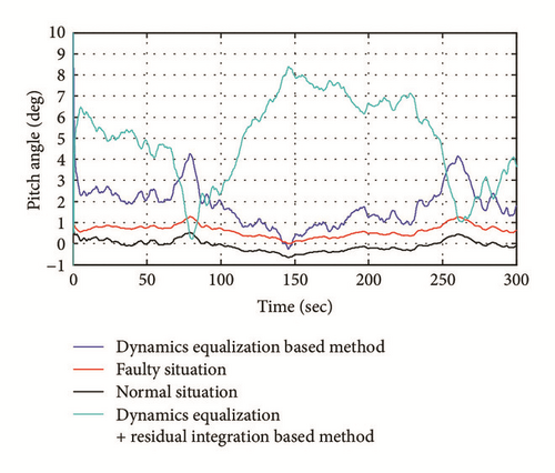
Figure 11 illustrates the pitch angle in the three situations. It can be stated that, in the faulty situation (red), the nominal regulator “tries” to beat the deviation in the speed by generating some pitch angles but without satisfactory results. By adding the term KδΩrf to the old control signal, the efforts become bigger and the difference between the points P1 and P2 is reduced. In the integrated method, the efforts become bigger and the integral part is evidently impacting the pitch angles to cancel the steady state error.
5. Conclusion
In this paper, a fault tolerant control method composed of several steps is proposed to deal with the loss of gearbox efficiency. This fault occurs due to the dusty environment of the modern large scale wind turbines. The first step is to estimate the shaft torque through a suitable transfer function between the rotor speed and the shaft torque. The last torque is used to estimate in real time the gearbox efficiency through a suitable loop. The estimated efficiency is used to select a corresponding eigenvalue from Figure 9. A design coefficient K is computed so the dynamics of the prefault and postfault cases are equalized. The rotor speed steady state is reconstructed by adding an integral part of the residual between the measured and reference rotor speed (zero deviation from operating point is desired).
On the other hand, a performance based conditions were given to help choosing the design integration parameter N. Based on the fact that the residual should not be impacted by the wind disturbance; a performance level θ has been proposed to verify |e|≺θ|ω|. The last inequality helps to give a negative (because ξ is by construction negative) inferior limit to N function of θ as .
The method is characterized by its ease of elaboration and parameters design and especially helps keeping a continuous production of the power in contrast to the generator torque based method.
Conflicts of Interest
The authors declare that there are no conflicts of interest regarding the publication of this paper.


