Multiobjective Optimization Design and Experimental Study of Desulfurization Dust Removal Centrifugal Pump Based on Immune Particle Swarm Algorithm
Abstract
In view of the problems of low efficiency, poor anticavitation performance, and curve hump for current centrifugal pump in the process of desulfurization and dust removal, the desulfurization dust removal centrifugal pump was designed. The velocity coefficient method was used for hydraulic design of centrifugal pump, and the three-dimensional modeling and numerical simulation of flow field of centrifugal pump were carried out by using computational fluid dynamics technology (CFD). The optimal mathematical model with the highest efficiency and the lowest pump net positive suction head (NPSHr) as the objective function was established under the condition of no curve hump. The immune particle swarm optimization algorithm was used to optimize the multiobjective function, and the optimal combination of the main parameters was obtained. The simulation results showed that, compared with the traditional centrifugal pump, the performance of the optimized centrifugal pump had been greatly improved, which eliminated the phenomenon of curve hump. Based on IH model chemical pump to build a prototype test platform, the experimental results of the external characteristics of the prototype pump and the optimization pump under different working conditions were obtained. At the rated flow rate, the optimization pump efficiency was increased by 13.30%, the head was increased by 11.52%, and NPSHr was decreased by 10.14%. The experimental results showed that the optimized indexes met the design requirements and improved the performance of centrifugal pump. At the same time, the accuracy of the immune particle swarm control method was verified, which provided some reference for the design of desulfurization dust removal centrifugal pump.
1. Introduction
Centrifugal pump is a widely used general machinery, mainly used in petrochemical, urban water supply and drainage, aerospace, and other fields [1]. At present, there are some problems in centrifugal pumps, such as low efficiency, poor anticavitation performance, and curve hump, especially in low speed centrifugal pumps. The early centrifugal pump development is mainly based on the Euler theory, univariate theory, binary theory, and flow similarity theory and other methods for hydraulic design and model conversion, whether the designer has a wealth of engineering experience is the key to determine the success of centrifugal pump design [2–8]. Industries, in order to achieve the function of desulfurization, usually to improve the chemical pump, but the improved efficiency of the chemical pump was low, could not meet the requirements of energy saving and environmental protection, and the operating conditions were not suitable for the desulfurization dust removal pump requirements. Aiming at the shortage of traditional centrifugal pump in this aspect, the structure design of desulfurization dust removal centrifugal pump was carried out by CFD technology, with the highest efficiency, the NPSHr as the objective function, and the no curve hump as the constraint conditions for multiobjective optimization, and the immune particle swarm control algorithm was used to optimize the calculation, so as to get a centrifugal pump with good performance.
2. Calculation of Mathematical Model for Desulfurization Dust Removal Centrifugal Pump
2.1. Hydraulic Design
The hydraulic design of desulfurization dust removal centrifugal pump is carried out by the velocity coefficient method [9], in which rotational speed n = 1450 r/min, flow rate Q = 50 m3/h, and head H = 20 m.
The design of desulfurization dust removal centrifugal pump is a single suction impeller: pump specific speed , hydraulic efficiency ηh = 1 + 0.0835lg(Q/n)1/3 = 0.860, volumetric efficiency , and mechanical efficiency .
2.2. Impeller Design
- (1)
Calculation of the suction port and outlet diameter of centrifugal pump
- (2)
Determination of impeller inlet diameter D1
- (3)
Determination of impeller outlet diameter D2
- (4)
Determination of impeller outlet width b2
- (5)
Determination of impeller inlet width b1
- (6)
Determination of blade inlet and outlet angle
The recommended blade inlet angle is , and the impact angle is Δβ = 3∘–15∘.
Due to , the selected inlet angle is β1 = 30∘.
- (7)
Determination of the number of blades Z
- (8)
Calculation of blade thickness and selection of blade packing angle
- (9)
Determination of impeller structure parameters
In summary, the main structural parameters of impeller are shown in Table 1.
| Parameters | Calculation results | Final results |
|---|---|---|
| DS (mm) | 80 | 80 |
| Dd (mm) | 56–80 | 65 |
| D1 (mm) | 89.4 | 90 |
| D2 (mm) | 256.6 | 260 |
| b1 (mm) | 12.1 | 12.5 |
| b2 (mm) | 22.9 | 23 |
| β1 (°) | 23–40 | 30 |
| β2 (°) | 16–40 | 30 |
| Z | 5.2 | 6 |
| S (mm) | 2.13 | 3 |
| φ (°) | 90–120 | 120 |
2.3. Calculation of Main Structural Parameters of Vortex Chamber
- (1)
Calculation of base circle diameter and vortex chamber inlet width
Since the base circle diameter calculation formula is: D3 = (1.03–1.08)D2 = 267.8–280.8 mm, the selected base circle diameter D3 = 270 mm.
- (2)
Calculation of each section area of vortex chamber
The calculation results of each section area of vortex chamber are shown in Table 2.
| Section | 1 | 2 | 3 | 4 | 5 | 6 | 7 | 8 |
|---|---|---|---|---|---|---|---|---|
| Area(cm2) | 1.91 | 3.81 | 5.72 | 7.63 | 9.53 | 11.44 | 13.34 | 15.25 |
3. Three-Dimensional Modeling and Flow Field Analysis of Desulfurization Dust Removal Centrifugal Pump
3.1. Centrifugal Pump Three-Dimensional Model
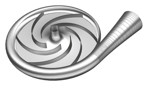
CFturbo is a professional impeller and volute design software, easy to operate, widely used in centrifugal pumps, centrifugal fans, turbines, and other rotating machinery designs [10–12]. The above design parameters are introduced into the CFturbo 10.0 software, and the three-dimensional model of centrifugal pump is shown in Figure 1 through the parameter setting.
3.2. Grid Division
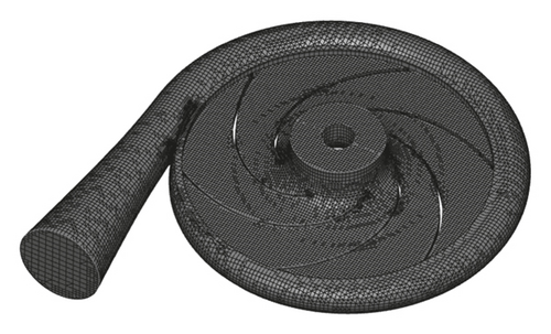
Pumplinx is a software developed for the hydraulic simulation and calculation of pump, which provides engineers with fast and accurate calculation results. The three-dimensional model of centrifugal pump is imported into the Pumplinx 3.4 software, and the Cartesian grid is divided, as shown in Figure 2; a total of 78668 grids are obtained.
In order to further verify the effect of grid number on the numerical simulation performance of centrifugal pump, six groups of grid numbers are selected to simulate the changes of centrifugal pump η, H, and NPSHr under the same working conditions. Grid independence analysis is shown in Table 3 [13].
| Schemes | Grid numbers | η(%) | H(m) | NPSHr(m) |
|---|---|---|---|---|
| 1 | 60000 | 81.63 | 16.76 | 1.03912 |
| 2 | 65000 | 81.75 | 18.65 | 1.03961 |
| 3 | 70000 | 82.23 | 19.24 | 1.04022 |
| 4 | 75000 | 82.25 | 19.28 | 1.04026 |
| 5 | 80000 | 82.27 | 19.32 | 1.04033 |
| 6 | 85000 | 82.29 | 19.33 | 1.04035 |
As can be seen from Table 3, when the number of grids is between 60000 and 70000, the number of grids has a great influence on each index of centrifugal pump. When the number of grids is between 70000 and 85000, the variation range of each index is small. Therefore, when the number of grids is more than 70000, the sensitivity of the external characteristics of centrifugal pump to the number of grids is small, and each index value tends to be stable. Visible, the number of selected impeller grids is reasonable.
3.3. Boundary Condition Setting
Before the flow field simulation, the boundary conditions are set. The rotating speed of impeller is n = 1450 r/min, the flow rate of pump is Q = 50 m3/h, the fluid medium is selected by water, and the turbulence model is selected as the k−ε model. The interface coupling between impeller and volute is coupled with dynamic-static interface. The inlet adopts the speed inlet boundary condition, the outlet boundary adopts the free outlet, and the surface of the solid wall has no slip.
3.4. Flow Field Simulation
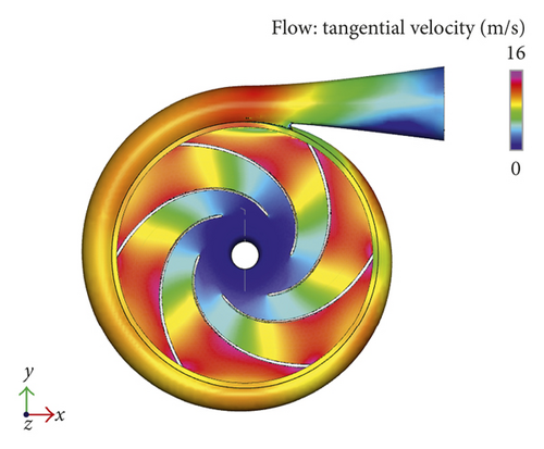
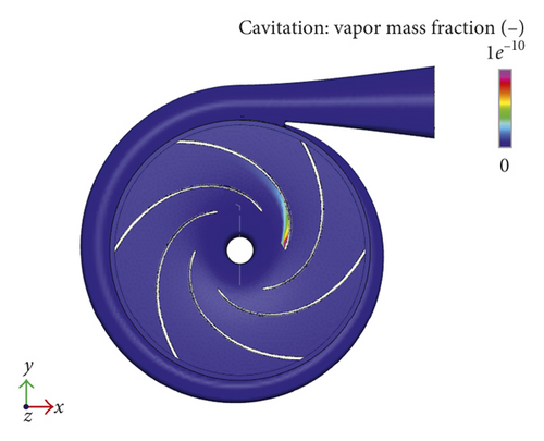
After setting the parameters, the flow field is simulated by Pumplinx 3.4 software. Figure 3 shows the pressure contour diagram, velocity contour diagram, and cavitation contour diagram of desulfurization dust removal centrifugal pump, respectively.
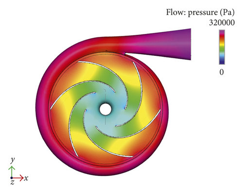
According to Figure 3(a), the pressure from the center of the impeller to the volute is gradually increased, reaching the maximum at the volute outlet, so that the fluid has enough energy to reach the specified head. However, the uneven pressure distribution on the volute and the reaction to the impeller may cause the vortex phenomenon among the blades.
As shown in Figure 3(b), the velocity from the center of the impeller to the outlet of the impeller is gradually increasing, the velocity distribution of impeller near the volute wall is uneven, and the vortex phenomenon is easy to appear, which affects the normal flow of fluid.
As shown in Figure 3(c), there is a large range of cavitation in the blades near the impeller inlet. This is because the impeller inlet pressure is very low, to reach the critical pressure of fluid at room temperature, resulting in cavitation phenomenon.
4. Centrifugal Pump Optimization Mathematical Model Establishment
In view of the above flow field simulation, with the highest efficiency and the lowest NPSHr as the objective function, the centrifugal pump was optimized with the constraint conditions of no curve hump.
4.1. Maximum Efficiency Model of Centrifugal Pump
4.2. Centrifugal Pump Minimum NPSHr Model
4.3. Constraint Conditions
5. Immune Particle Swarm Control Algorithm Design
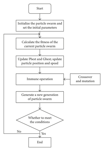
The immune particle swarm algorithm is a new improved particle swarm algorithm based on the immune mechanism of the biological system. The control effect is obvious, which has the characteristics of fast convergence speed, high convergence precision, and strong adjustment ability. In this paper, Matlab 7.0 software is used to write immune particle swarm optimization algorithm to optimize the multiobjective function.
Fitness function f = 1/J, and the greater the fitness, the higher the accuracy of particles.
The parameter optimization process is shown in Figure 4 [17, 18].
6. Optimization Design of Desulfurization Dust Removal Centrifugal Pump
6.1. Parameter Determination
By calculating, the constraints could be obtained as follows: 63.7 mm < D1 < 95.6 mm, 21.6 mm < b1 < 32.4 mm, 235.4 mm < D2 < 274.6 mm, 9.0 mm < b2 < 13.5 mm, 23° < β1 < 40°, 10° < β2 < 40°, 90° < φ < 130°, and 4 < Z < 9.
Particle size N = 60, maximum number of iterations max DT = 200, learning factor c1 = c2 = 1.624, inertia weight coefficient ω = 0.628, crossover probability pc = 0.576, mutation probability pm = 0.01 − [1 : 1 : N]∗0.01/N, and weight ω1 = 0.003, ω2 = 0.87, andω3 = 96.
6.2. Analysis of Results after Optimization
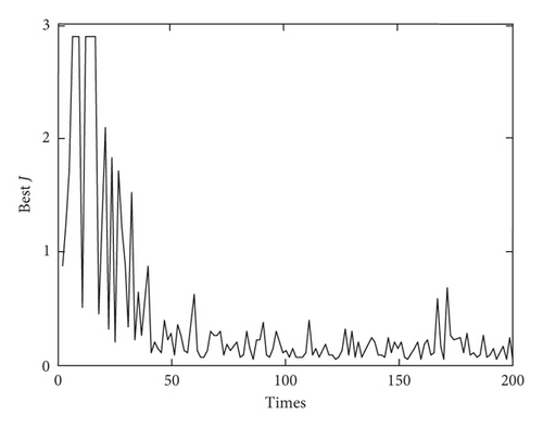
The immune particle swarm algorithm is programmed by Matlab 7.0 software, and the iterative result of optimal solution is shown in Figure 5.
The optimized parameters of impeller are shown in Table 4.
| Parameters | D1 (mm) | b1 (mm) | D2 (mm) | b2 (mm) | β1 (°) | β2 (°) | φ (°) | Z |
|---|---|---|---|---|---|---|---|---|
| Prototype pump | 90 | 23 | 260 | 12.5 | 30 | 30 | 120 | 6 |
| Optimization pump | 94 | 26 | 262 | 11 | 28 | 18 | 110 | 6 |
6.3. Simulation of Flow Field after Optimization
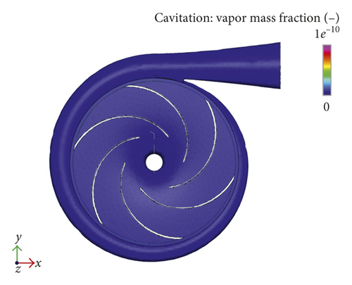
According to the optimized parameters, the parameters are remodeled, and the CFD analysis is carried out, as shown in Figure 6.
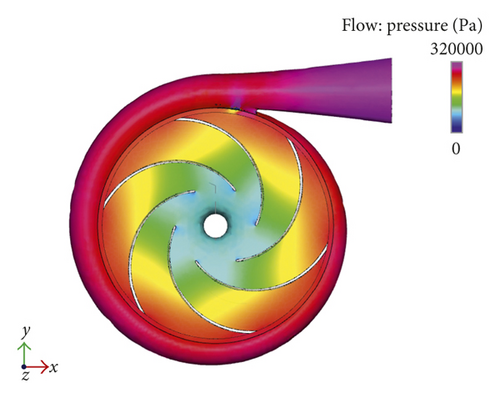
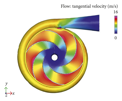
As can be seen from Figure 6(a), the pressure distribution on the volute of the optimization pump is relatively uniform, the energy loss in the volute is small, and the vortex phenomenon between blades is avoided.
As can be seen from Figure 6(b), the velocity of the fluid near the volute wall of the optimization pump is relatively uniform, and the vortex phenomenon is avoided.
As can be seen from Figure 6(c), the cavitation near the inlet of the impeller of the optimization pump is obviously reduced, and the cavitation phenomenon is basically eliminated.
From the optimized pressure contour diagram, velocity contour diagram, and cavitation contour diagram, it can be seen that the effect of the initial design structure of centrifugal pump has been significantly improved, and the overall performance of centrifugal pump has a certain promotion.
6.4. Simulation of External Characteristics
In order to verify the feasibility of the optimization scheme, the external characteristics of the prototype pump and the optimization pump under rated operating conditions are simulated respectively (where rated flow Qd = 50 m3/h), and the simulation results are shown in Table 5.
| Optimization index | Prototype pump | Optimization pump | Optimization rate (%) |
|---|---|---|---|
| η(%) | 82.28 | 92.23 | 12.09 |
| H(m) | 19.31 | 21.43 | 10.98 |
| NPSHr(m) | 1.04030 | 0.94876 | 8.80 |
According to the simulation results of the external characteristics, the optimization pump efficiency is improved by 12.09%, the head is increased by 10.98%, and NPSHr is reduced by 8.80%. At the same time, β2Z0.773 before and after optimization are 119.85 and 71.91, respectively, and the curve hump is eliminated.
7. Experimental Verification
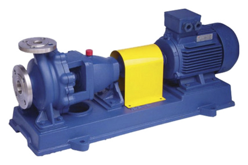
In order to verify the accuracy of immune particle swarm optimization, an external characteristic test bench is built with IH model horizontal stainless steel chemical centrifugal pump, as shown in Figures 7 and 8, respectively. IH model chemical pump is mainly composed of pump body, shaft key, impeller nut, packing ring, brake pad, packing gland, shaft, pump cover, and suspension bearing components. The chemical pump has the advantages of reasonable and reliable layout of water conservancy, small size, light weight, good anticavitation performance, low power consumption, easy maintenance, and high work efficiency.

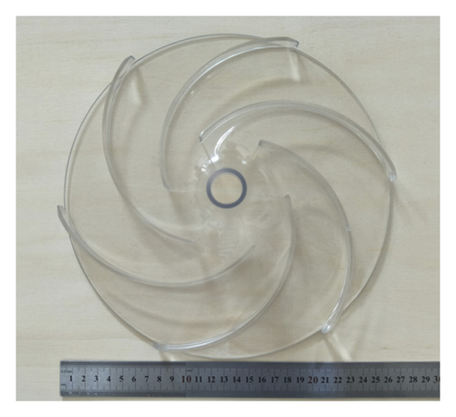
Based on the optimized impeller structure parameters given in Table 4, the impeller is made as shown in Figure 9, and the impeller material is made of transparent rigid polyvinyl chloride. The internal flow field of centrifugal pump is measured under 6 working conditions of 0.2Qd, 0.4Qd, 0.6Qd, 0.8Qd, 1.0Qd, and 1.2Qd. Figure 10 shows the external characteristic curves of the prototype pump and the optimization pump.
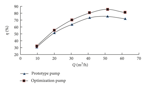
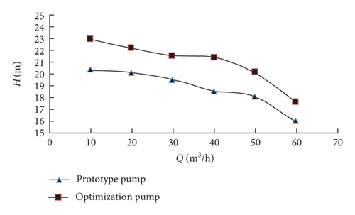
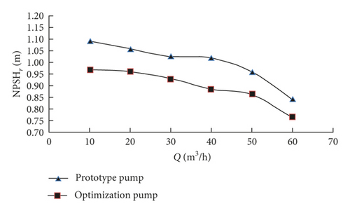
According to the pump characteristic curves, the experimental values of the optimization pump and the prototype pump are in good agreement, which can accurately reflect the change trend of η, H, and NPSHr with the variation of flow rate.
There is a small error between the simulation value and the experimental value; the main reason is that, in the numerical simulation experiment of centrifugal pump hydraulic design, the leakage of impeller sealing ring, volume loss caused by axial force, and mechanical loss caused by centrifugal pump in the working process is not considered.
The experimental results of each index of prototype pump and optimization pump under different working conditions are extracted from Figure 10, as shown in Table 6.
| Indexes | Q(m3/h) | |||||
|---|---|---|---|---|---|---|
| 10 | 20 | 30 | 40 | 50 | 60 | |
| Prototype pump η(%) | 32.12 | 51.77 | 63.36 | 72.69 | 74.43 | 71.24 |
| Optimization pump η(%) | 33.46 | 55.06 | 69.44 | 79.17 | 84.33 | 79.71 |
| Δη(%) | 4.17 | 6.36 | 9.60 | 8.91 | 13.30 | 11.89 |
| Prototype pump H(m) | 20.36 | 20.11 | 19.49 | 18.53 | 18.06 | 15.97 |
| Optimization pump H(m) | 22.97 | 22.22 | 21.55 | 21.41 | 20.14 | 17.64 |
| ΔH(%) | 12.82 | 10.49 | 10.57 | 15.54 | 11.52 | 10.46 |
| Prototype pump NPSHr(m) | 1.09198 | 1.05678 | 1.02558 | 1.01914 | 0.95987 | 0.84287 |
| Optimization pump NPSHr(m) | 0.97007 | 0.9584 | 0.92943 | 0.88455 | 0.86255 | 0.76461 |
| ΔNPSHr(%) | 11.16 | 9.31 | 9.38 | 13.21 | 10.14 | 9.28 |
As can be seen from Table 6, under different working conditions, the optimization pump efficiency and head are all larger than the prototype pump, and the optimization pump NPSHr is less than the prototype pump. At the rated flow rate, the optimization pump efficiency is increased by 13.30%, the head is increased by 11.52%, and NPSHr is decreased by 10.14%, which achieve the desired optimization goal.
In summary, every index of the optimization pump has been significantly improved, and it can be concluded that the immune particle swarm optimization algorithm is feasible; the control strategy is further verified by the centrifugal pump external characteristic test.
8. Conclusion
- (1)
The hydraulic design of desulfurization dust removal centrifugal pump was carried out by the velocity coefficient method, and the main structural parameters of impeller and volute were obtained. The three-dimensional model of centrifugal pump was established by CFturbo 10.0 software, and the centrifugal pump was numerically simulated and analyzed by Pumplinx 3.4 software.
- (2)
An optimization mathematical model with the highest efficiency and the lowest NPSHr as the objective function was established under the condition of no curve hump. A total of eight indexes of D1, b1, D2, b2, β1, β2, φ, and Z were optimized by the immune particle swarm algorithm.
- (3)
Through the simulation and analysis of the optimization results, the optimization pump efficiency was increased from 82.28% to 92.23%, the head was increased from 19.31 m to 21.43 m, and NPSHr was decreased from 1.04030 m to 0.94876 m; the curve hump problem was eliminated. The overall performance of centrifugal pump was improved significantly, and the feasibility of immune particle swarm optimization was verified.
- (4)
Based on the IH model chemical pump, the external characteristic test bench was built, and the external characteristic curves of each index parameter of centrifugal pump under different working conditions were obtained. The variation law of experimental values of all index parameters was basically consistent before and after optimization, and compared with the prototype pump, the experimental values of the optimization pump were significantly improved. The accuracy of the immune particle swarm optimization control strategy was verified, which provided some reference value for the structural optimization design of desulfurization dust removal centrifugal pump in the future.
- (5)
Taking centrifugal pump as the research object, the main indexes of centrifugal pump were optimized by immune particle swarm optimization algorithm, which improved the hydraulic performance of centrifugal pump. Due to the limitation of research conditions, this paper only studied the optimization of pump efficiency, head, and NPSHr, without considering the optimization of other indicators. In the following research work, based on immune particle swarm optimization control strategy, the influence of the main geometric parameters of centrifugal pump on the pump characteristics will be considered comprehensively, in order to improve the working performance of centrifugal pump.
Conflicts of Interest
The authors declare that there are no conflicts of interest regarding the publication of this paper.
Acknowledgments
This project was supported by Key Project of Natural Science Research in Colleges and Universities of Anhui Province, China (KJ2017A450), Anhui Province University Outstanding Young Talent Support Program Project, China (gxyq2017071), and Natural Science Foundation of Chaohu University, China (XLZ-201503).


