Volume 2017, Issue 1 2783682
Research Article
Open Access

A New Iterative Numerical Continuation Technique for Approximating the Solutions of Scalar Nonlinear Equations

Grégory Antoni

Corresponding Author

Grégory Antoni

IFSTTAR, Aix-Marseille Université, LBA UMR T24, 13016 Marseille, France univmed.fr

Search for more papers by this author
First published: 16 January 2017
Citations: 1
Academic Editor: Yurong Liu

Abstract

The present study concerns the development of a new iterative method applied to a numerical continuation procedure for parameterized scalar nonlinear equations. Combining both a modified Newton’s technique and a stationary-type numerical procedure, the proposed method is able to provide suitable approximate solutions associated with scalar nonlinear equations. A numerical analysis of predictive capabilities of this new iterative algorithm is addressed, assessed, and discussed on some specific examples.

1. Introduction

The resolution of scalar nonlinear equations is an issue frequently encountered in many branches of physical sciences such as mechanics [15]. Although, in the literature, the most used numerical methods are either the classical Newton’s technique [3, 4, 6] or modified Newton-type procedures [710], they suffer from the main disadvantage of being held in check in the presence of critical points [11]. In order to overcome this deficiency, we propose to develop a new iterative algorithm applied to a numerical continuation procedure [5] for providing the approximate solutions associated with parameterized scalar nonlinear equations. The presented algorithm is based on a modified Newton-type method coupled with a stationary numerical technique. This study is organized in the following manner: (i) in Section 2, the standard numerical continuation procedure is briefly recalled including some classical algorithms; (ii) in Section 3, the new proposed iterative numerical method is presented in detail; (iii) in Section 4, the predictive abilities associated with this new iterative algorithm are tested and evaluated on some examples.

2. Standard Numerical Continuation Methods

2.1. Problem Statement
We consider the parameterized scalar nonlinear equation in the following form:
()
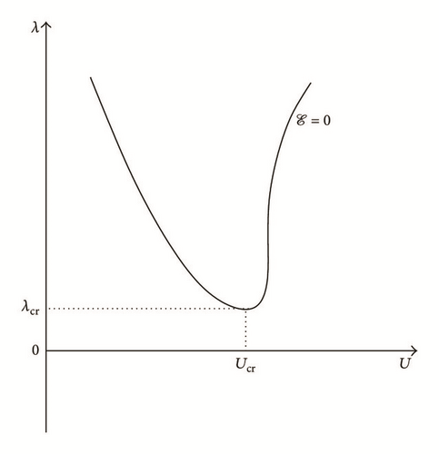
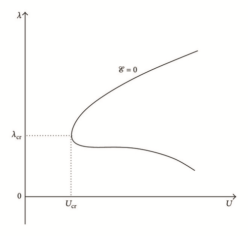
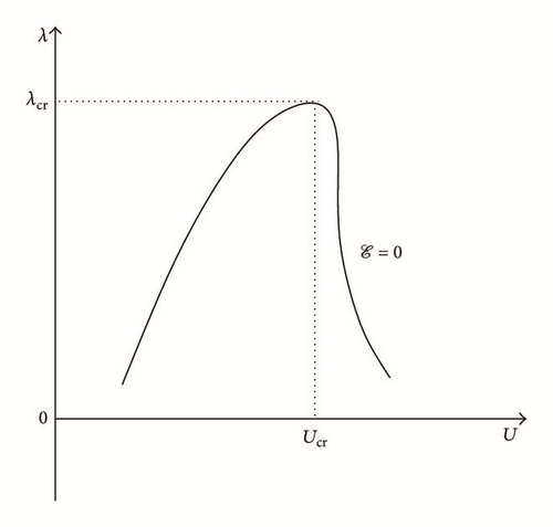
where X denotes the real-valued “solution” variable associated with the nonlinear problem under consideration and L is the real-valued scalar "parameter" variable. It is important to emphasize the following: (i) the parametrized scalar nonlinear equation (see (1)) may include critical points (Ucr, λcr) (see Figure 1); (ii) the couple (X, L) can depend on another parameter such as (1) reading ; (iii) in the framework of solid mechanics, (1) represents the mechanical equilibrium equation and the “solution” variable X and the scalar “parameter” variable L denote the displacement and the mechanical load, respectively (i.e., XU and Lλ). Within this context, the natural parameter p is the physical time t; that is, (1) can be written as follows:
()
Details are in the caption following the image
Schematic diagram of a two-dimensional curve which is defined by a parameterized scalar nonlinear equation (i.e., ) which presents only one critical point (Ucr, λcr) in four different situations ((a), (b), (c), and (d)).
Details are in the caption following the image
Schematic diagram of a two-dimensional curve which is defined by a parameterized scalar nonlinear equation (i.e., ) which presents only one critical point (Ucr, λcr) in four different situations ((a), (b), (c), and (d)).
Details are in the caption following the image
Schematic diagram of a two-dimensional curve which is defined by a parameterized scalar nonlinear equation (i.e., ) which presents only one critical point (Ucr, λcr) in four different situations ((a), (b), (c), and (d)).
Details are in the caption following the image
Schematic diagram of a two-dimensional curve which is defined by a parameterized scalar nonlinear equation (i.e., ) which presents only one critical point (Ucr, λcr) in four different situations ((a), (b), (c), and (d)).

2.2. Some Commonly Used Algorithms

2.2.1. Classical Newton and Newton-Type Procedures

By placing in the context of solid mechanics and considering that the physical time t = [0, T] (with ) is divided into (N + 1)-subintervals [tn, tn+1] (i.e., T = (N + 1)Δt with Δt = Δtn+1 = tn+1tn and tn+1 = (n + 1)Δt, ∀n = 0, …, N with ), we have the displacement U(t) and the mechanical load λ(t) at the incremental time tn (resp., tn+1) that are written as follows: U(tn) ≡ Un and λ(tn) ≡ λn (resp., U(tn+1) ≡ Un+1 and λ(tn+1) ≡ λn+1).

For solving numerically (2), we consider the discrete-time interval [tn, tn+1] and we perform a Taylor series expansion of the function (representing here the mechanical equilibrium of solid) in the first order at point (with λn+1 being fixed and constant):
()
where denotes the higher-order terms with the Landau notation o(·) associated with the asymptotic behaviour of the function (considering only the variable quantity U), ‖∙‖ is Euclidean norm associated with the quantity ∙ (here, Euclidean distance reduces to the absolute value |∙| since that there is only one-variable U, i.e., ) and (resp., ) denote the kth (resp., (k + 1)th) iterative solution associated with the variable ▲ at the incremental time tn+1 (with ), and is the first-order partial derivative operator associated with the function with respect to U (at point which is kth iterative displacement of the incremental time tn+1) for fixed and constant mechanical load λ (at point λn+1 which is the value of parameter of the incremental time tn+1). It should be underscored that the variable ■n (resp., ■n+1) without the exponent k or (k + 1) represents a converged (resp., known) quantity at the incremental time tn (resp., tn+1).
In line with (3), we can define the following:
  • (i)

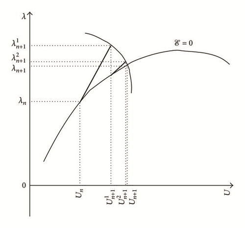
    classical Newton’s algorithm (see case (a) of Figure 2; cf. [3, 4, 7]):

    ()

  • (ii)

    Newton-type algorithm (see case (b) of Figure 2; cf. [3, 4, 7]):

    ()

  • where denotes a coefficient which checks with , sgn(·) is the sign function (such as sgn(φ) = −1 when φ < 0, sgn(φ) = 1 when φ > 0, and sgn(φ) = 0 when φ = 0), and |φ| is the absolute-value function (such as |φ | = −φ when φ < 0 and |φ | = φ when φ ≥ 0). It is worth noting that if then this is the classical Newton’s algorithm and if κ = C (with C being the constant coefficient which does not depend on the point and checking and ) then this is the modified Newton’s algorithm.
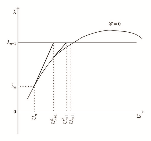
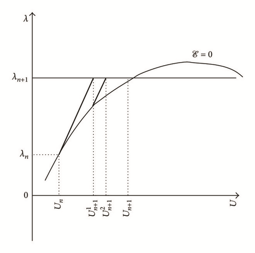
Details are in the caption following the image
Schematic diagram of some numerical continuation algorithms: (a) classical Newton’s; (b) modified Newton-type; (c) arclength; (d) pseudo-arclength.
Details are in the caption following the image
Schematic diagram of some numerical continuation algorithms: (a) classical Newton’s; (b) modified Newton-type; (c) arclength; (d) pseudo-arclength.
Details are in the caption following the image
Schematic diagram of some numerical continuation algorithms: (a) classical Newton’s; (b) modified Newton-type; (c) arclength; (d) pseudo-arclength.
Details are in the caption following the image
Schematic diagram of some numerical continuation algorithms: (a) classical Newton’s; (b) modified Newton-type; (c) arclength; (d) pseudo-arclength.

2.2.2. Standard Arclength and Pseudo-Arclength Procedures

Similar to previous approach (see Section 2.2.1), we perform a Taylor series expansion of the function (representing the mechanical equilibrium of solid) in the first order at point :
()
where denotes the higher-order terms with the Landau notation o(·) associated with the asymptotic behaviour of the function (considering the variable quantities (U, λ)) and (resp., is the first-order partial derivative operator associated with the function with respect to λ (resp., U) at point (resp., ) for fixed and constant displacement U (resp., mechanical load λ) at point (resp., ) which is kth iterative variable of incremental time tn+1.
Combined with (5), we introduce another scalar equation (so-called “constraint condition”); that is,
  • (i)

    the equation is nonlinear type (second order) in the case of an arclength algorithm (see case (c) of Figure 2) (e.g., Crisfield procedure [5, 12, 13]);

  • (ii)

    the equation is linear type in the case of a pseudo-arclength algorithm (see case (d) of Figure 2) (e.g., Riks [1417], Ramm [18, 19], or Wempner [20] procedures).

It may be stressed that there exist many other methods used for numerical continuation procedures; one of them, which is not present here, is called “normal flow algorithm” or “Davidenko’s flow algorithm” (see [21, 22] for more details); the mechanical equilibrium equation of solid associated with the Davidenko’s flow reads , where χ denotes the perturbation parameter.

3. A New Iterative Numerical Continuation Method

3.1. Proposed Algorithm
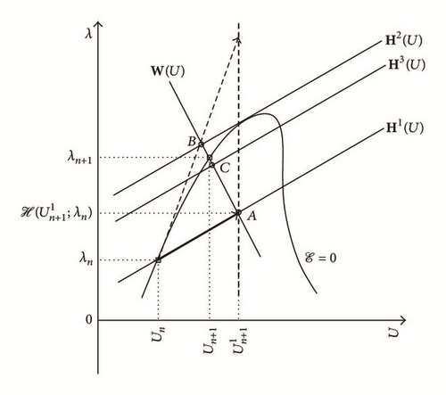
In this section, we present a new iterative numerical continuation procedure for approximating the solutions associated with any parameterized scalar nonlinear equations. The proposed iterative algorithm belongs to the family of predictor-corrector methods, and it uses both a modified Newton’s method and a stationary-type numerical technique. The stationary procedure allows reducing the considered scalar nonlinear equation (see (1)) to only one explicit equation such as
()
where † is the considered variable and ⋆ is the fixed and constant parameter. It should be stressed that the derivative of the function (see (1)) checks that
()
where D denotes the first-order total derivative operator (with .
When considering both a discrete-time interval [tn, tn+1] and an orthonormal basis , the direction vector associated with the tangent straight line at point (Un, λn) can be written as follows (with the stationary procedure (7)):
()
with
()
()
where denotes the unit vector of the basis such as (∀i = U, λ) and are the components associated with the vector in the orthonormal basis . It should be noted that, in (11), the term since that (Un, λn) is the mechanical equilibrium point at the time tn.
For crossing more easily some critical points (Ucr, λcr) associated with the nonlinear function , we introduce a new director vector associated with the straight line at point (Un, λn) at the time tn such as
()
with
()
where (with i = U, λ) are the components associated with the vector in the orthonormal basis and α and β are two parameters ().
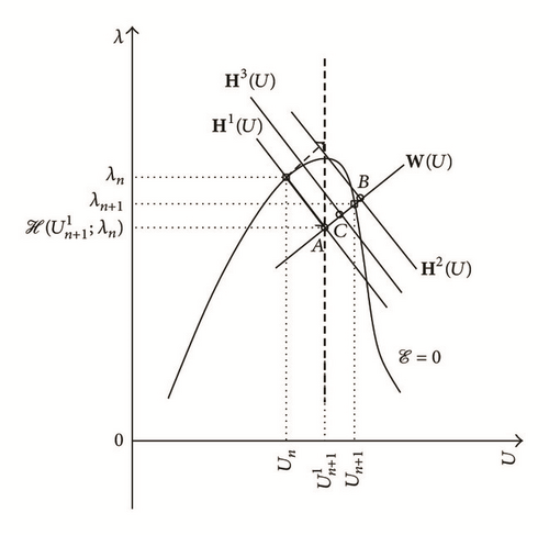
Using (12) and (13), we define the equation of the straight line passing through the point and with the director vector that must satisfy the following relation (see Figure 3):
()
with
()
Details are in the caption following the image
Schematic diagram of the new iterative algorithm associated with the numerical continuation procedure (see Section 3). Notations: (i) the dashed straight arrow denotes the true tangent straight line (); (ii) the bold solid straight arrow is the modified tangent straight line for the converged point (square point) at the time tn (); (iii) the perpendicular solid straight line with the bold solid straight arrow is the iterative line at the time tn (); (iv) the other parallel solid straight lines with respect to the bold solid straight arrow are the kth iterative iterative lines at the time tn+1 ( with θ = θ1  ∀k = 1,2, 3) with the kth iterative points (circle points) such that (iv-a) if k = 1, then ; (iv-b) if k = 2, then ; and (iv-c) if k = 3, then .
For the first iterative step (i.e., k = 1), the iterative point must satisfy the following relation (with , ∀ϕ = U, λ):
()
where γ is a parameter ().
In line with (16), the iterative point checks (see Figure 3)
()
with
()
Using (6), (7) and (8), we have (with and ):
()
In line with (19) and considering (7) combined with the updated iterative point obtained with (17) and (18), we can approximate the new iterative point as
()
For the other iterative steps (i.e., k > 1), we introduce the straight line passing thought the point and with the director vector must satisfy the following relations (see Figure 3):
()
with
()
where (with i = U, λ) are the components associated with the vector in the orthonormal basis .
The (k + 1)th iterative solution is obtained when with ;that is,
()
with
()
In the same way with (20), the iterative solution can be determined as follows (with ):
()

3.2. Some Comments

It is important to emphasize the following:
  • (1)

    For the first iterative step at the first increment (i.e., k = 1 and n = 0), the choice of sign “±” in (17) is arbitrary and depends only on the direction for beginning the numerical continuation procedure. Further in this study, we adopt the sign “+.” Nevertheless, for the other first iterative steps at other increments (i.e., k = 1 and n ≥ 1), we consider a certain continuity of path with respect to the previous converged increment and we adopt the following rule: (i) the sign “+” when or and ; (ii) the sign “−” when or and .

  • (2)

    The new proposed iterative algorithm (see Section 3.1) uses the first-order partial derivative operator as classical Newton’s algorithm (see Section 2.2.1), but unlike this latter, the critical points can be passed without relatively strong difficulties. Based on a modified Newton’s procedure, the new algorithm considers iterative steps of predictions and corrections which depend on both the first-order partial derivative operator , ∀k = 0, …, K, ∀n = 0, …, N) and its inverse , ∀k = 0, …, K, ∀n = 0, …, N) modulated by two parameters (α and β) allowing to pass through the limit points for the first (see (17) and (18)) and other iterations (see (23) and (24)) during a discrete-time interval.

  • (3)

    The two values associated with the function Θ (see (15) and (24)), which is a linear combination of the first-order partial derivative operator and its inverse , ∀k = 0, …, K, ∀n = 0, …, N), represent the fact that are considered: (i) when Θ = Θ1, the initial straight line previously converged (i.e., with k = 0, ∀n = 0, …, N); (ii) when Θ = Θ2, the current iterative straight line is (∀k = 0, …, K, ∀n = 0, …, N).

  • (4)

    The new proposed algorithm is composed of three parameters: α, β, and γ. The optimal values of these parameters depend clearly on the nonlinear function under consideration. Therefore, a sensibility analysis must be conducted in order to obtain these optimal values. An alternative approach consists, in the first time, to choose the following values: (i) for α given: (i-a) β = α and γ = 1; (i-b) β = 1/α and γ = 1; and (i-c) β = 0 and γ = 1; (ii) for β given: (ii-a) α = 0 and γ = 1. On the other hand, in the case where α = 1 and β = 0, the new proposed algorithm reduces to a pseudo-arclength type procedure (see Section 2.2.2).

4. Some Numerical Examples

4.1. Preliminary Remarks

In the current section, we propose to test and evaluate the accuracy, efficiency, and robustness associated with the developed iterative method associated with the numerical continuation procedure in Section 3 on some scalar nonlinear equations. Moreover, all the numerical results of this section have been obtained with MATLAB software (see [7]).

New Iterative Numerical Continuation Algorithm (See Figure 3)
  • (i)

    For the iterative solution (k ≥ 1), one has the following:

    • (a)

      For the first iteration (k = 1),

      ()

    • with

      ()

    • (b)

      For the other iterations (k ≥ 2),

      ()

  • with

    ()

  • (ii)

    For the iterative solution (k ≥ 1),

    ()

It is important to emphasize the following:
  • (i)

    On the one hand, we consider only the case where Θ = Θ1 for the new continuation algorithm (see (26)–(30)) used in this section.

  • (ii)

    On the other hand, we introduce four types of Convergence Criterion (CCl) (with l = 1, …, 4) in order to stop the iterative process associated with the new proposed algorithm:

    ()

  • where Kmax represents the maximum number of iterations, ϵre and ϵae1 (resp., ϵae2) are the tolerance parameters associated with the residue error of the function and approximation error criterion of displacement U (resp., mechanical load λ). In what follows, we consider the following values for each CC: Kmax = 30, ϵre = 10−10, and ϵae1 = ϵae2 = 10−10.

4.2. Examples

We consider the following scalar nonlinear equations:
()
where ϑ, τ, ν, μ, and η are five parameters chosen with these values: ϑ = 102, τ = 0.5, ν = 10, μ = 100, and η = 10−2.

4.3. Results and Discussion

4.3.1. Predictive Numerical Capabilities

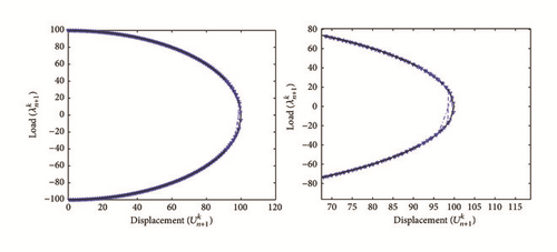
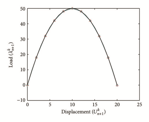
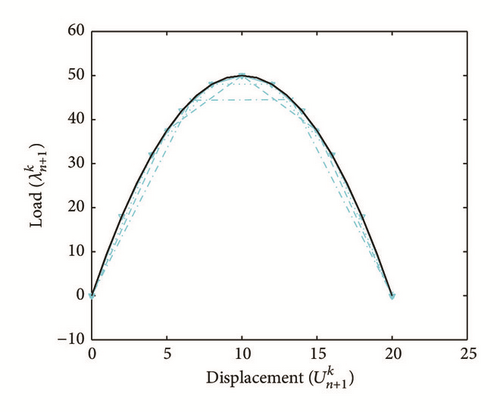
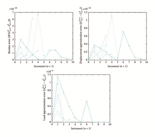
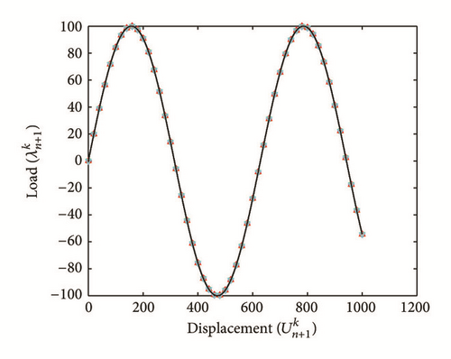
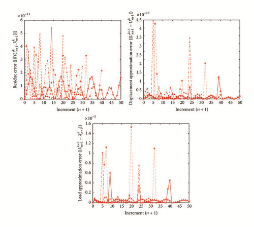
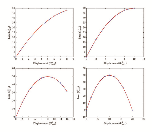
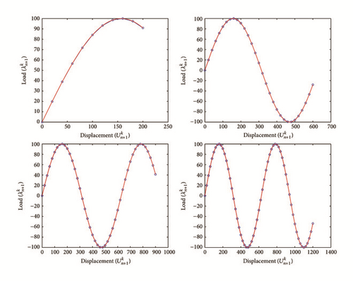
All the numerical results associated with scalar nonlinear functions (E1) to (E3) (see Section 4.2) are presented in Figures 46. The obtained numerical results show fairly clearly that the new proposed iterative numerical algorithm (see Section 3) is capable of giving convenient approximate solutions associated with parameterized scalar nonlinear equations including critical points. Indeed, in Example 1 (E1), there are four critical points and we can see that the new iterative algorithm is able to pass all these points: (i) the first (Ucr, λcr) = (100,0) (representing case (c) of Figure 1); (ii) the second (Ucr, λcr) = (0, −100) (representing case (b) of Figure 1); (iii) the third (Ucr, λcr) = (−100,0) (representing case (d) of Figure 1); and (iv) the fourth (Ucr, λcr) = (0,100) (representing case (a) of Figure 1). In Example 2 (E2), there is only one critical point (Ucr, λcr) = (10,50) (representing case (a) of Figure 1) and the new iterative algorithm passes without excessive difficulty this singularity. In the same way, in Example 3 (E3), there are periodic critical points and we can see that the new algorithm passes again the first (Ucr, λcr) = (157,100) (representing case (a) of Figure 1) and the second (Ucr, λcr) = (471, −100) (representing case (b) of Figure 1) singularity associated with the nonlinear function in the interval [0, Tper] (where Tper = 2π/η ≈ 628.31 denotes the period of the sinusoidal function). In the light of all the numerical results obtained in Figures 4, 5, and 6, the new iterative numerical continuation algorithm enables passing through the critical points and predicting the approximate solutions associated with parameterized scalar nonlinear equations.
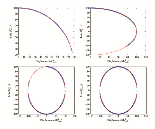
Details are in the caption following the image
Evolution of the approximate solutions () obtained with the new iterative numerical continuation algorithm (blue solid line with circles; see (26)–(30) with Θ = Θ1) and compared with the exact solution (red solid line) for Example 1 (E1) with the following parameters: α = 50, β = −100, and γ = 1.
Details are in the caption following the image
Evolution of the approximate solutions () obtained with the new iterative numerical continuation algorithm (blue solid line with circles; see (26)–(30) with Θ = Θ1) and compared with the exact solution (red solid line) for Example 2 (E2) with the following parameters: α = 1000, β = 500, and γ = 2.
Details are in the caption following the image
Evolution of the approximate solutions () obtained with the new iterative numerical continuation algorithm (blue solid line with circles; see (26)–(30) with Θ = Θ1) and compared with the exact solution (red solid line) for Example 3 (E3) with the following parameters: α = 10000, β = 200, and γ = 20.

4.3.2. Sensibility Analysis

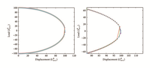
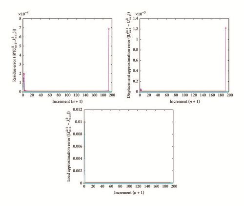
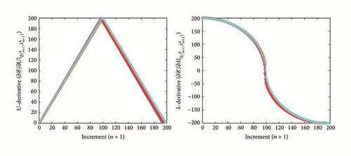
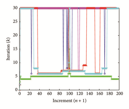
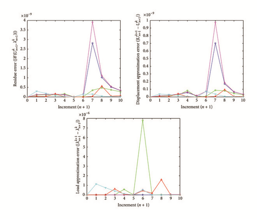
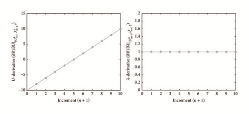
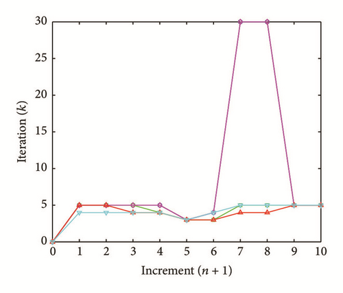
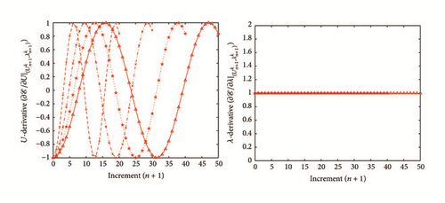
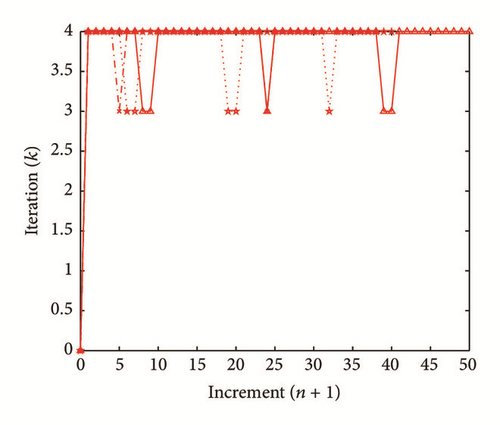
In this section, we propose a sensibility analysis for evaluating the influence of different values assigned with the parameters (α, β, and γ) used by the new iterative numerical continuation algorithm (see Section 3). All the numerical results associated with the scalar nonlinear functions (E1), (E2), and (E3) (see Section 4.2) with different values of the parameters (α, β, and γ) are presented in Figures 730.

Details are in the caption following the image
Evolution of the approximate solutions () obtained with the new iterative numerical continuation algorithm (see (26)–(30) with Θ = Θ1) and compared with the exact solution (black solid line) for Example 1 (E1) with the following parameters: (i) α = 50, β = −100, and γ = 1 (blue solid line with circles); (ii) α = 3000, β = −1, and γ = 1 (green solid line with squares); (iii) α = 30, β = −200, and γ = 1 (magenta solid line with diamonds); (iv) α = 80, β = −600, and γ = 1 (red solid line with upward-pointing triangles); (v) α = 100, β = −8, and γ = 1 (cyan solid line with downward-pointing triangles).
Details are in the caption following the image
Evolution of the residue error of the function (), the approximation error of displacement U (), and mechanical load λ () obtained with the new iterative numerical continuation algorithm (see (26)–(30) with Θ = Θ1) for Example 1 (E1) with the following parameters: (i) α = 50, β = −100, and γ = 1 (blue solid line with circles); (ii) α = 3000, β = −1, and γ = 1 (green solid line with squares); (iii) α = 30, β = −200, and γ = 1 (magenta solid line with diamonds); (iv) α = 80, β = −600, and γ = 1 (red solid line with upward-pointing triangles); (v) α = 100, β = −8, and γ = 1 (cyan solid line with downward-pointing triangles).
Details are in the caption following the image
Evolution of the approximate solutions of first-order partial derivatives associated with the displacement U (()) and the mechanical load λ () obtained with the new iterative numerical continuation algorithm (see (26)–(30) with Θ = Θ1) for Example 1 (E1) with the following parameters: (i) α = 50, β = −100, and γ = 1 (blue solid line with circles); (ii) α = 3000, β = −1, and γ = 1 (green solid line with squares); (iii) α = 30, β = −200, and γ = 1 (magenta solid line with diamonds); (iv) α = 80, β = −600, and γ = 1 (red solid line with upward-pointing triangles); (v) α = 100, β = −8, and γ = 1 (cyan solid line with downward-pointing triangles).
Details are in the caption following the image
Evolution of the number of iterations (k) for each increment (n) obtained with the new iterative numerical continuation algorithm (see (26)–(30) with Θ = Θ1) for Example 1 (E1) with the following parameters: (i) α = 50, β = −100, and γ = 1 (blue solid line with circles); (ii) α = 3000, β = −1, and γ = 1 (green solid line with squares); (iii) α = 30, β = −200, and γ = 1 (magenta solid line with diamonds); (iv) α = 80, β = −600, and γ = 1 (red solid line with upward-pointing triangles); (v) α = 100, β = −8, and γ = 1 (cyan solid line with downward-pointing triangles).
Details are in the caption following the image
Evolution of the approximate solutions () obtained with the new iterative numerical continuation algorithm (blue line; see (26)–(30) with Θ = Θ1) and compared with the exact solution (black solid line) for Example 1 (E1) with the parameters α = 50 and β = −100 and for different values of the parameter γ: (i) γ = 1 (blue solid line with upward-pointing triangles); (ii) γ = 1.4 (blue dotted line with pentagrams); (iii) γ = 1.5 (blue dash-dot line with plus signs); (iv) γ = 1.6 (blue dashed line with crosses).
Details are in the caption following the image
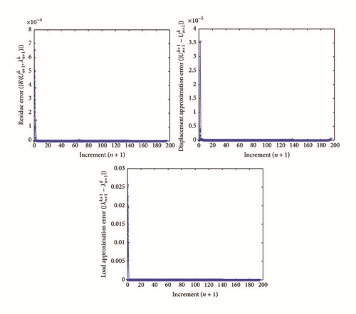
Evolution of the residue error of the function (), the approximation error of displacement U (), and mechanical load λ () obtained with the new iterative numerical continuation algorithm (blue line; see (26)–(30) with Θ = Θ1) for Example 1 (E1) with the parameters α = 50 and β = −100 and for different values of the parameter γ: (i) γ = 1 (blue solid line with upward-pointing triangles); (ii) γ = 1.4 (blue dotted line with pentagrams); (iii) γ = 1.5 (blue dash-dot line with plus signs); (iv) γ = 1.6 (blue dashed line with crosses).
Details are in the caption following the image
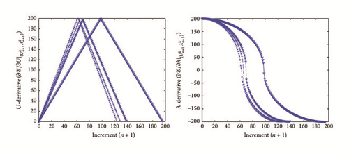
Evolution of the approximate solutions of first-order partial derivatives associated with the displacement U () and the mechanical load λ () obtained with the new iterative numerical continuation algorithm (blue line; see (26)–(30) with Θ = Θ1) for Example 1 (E1) with the parameters α = 50 and β = −100 and for different values of the parameter γ: (i) γ = 1 (blue solid line with upward-pointing triangles); (ii) γ = 1.4 (blue dotted line with pentagrams); (iii) γ = 1.5 (blue dash-dot line with plus signs); (iv) γ = 1.6 (blue dashed line with crosses).
Details are in the caption following the image
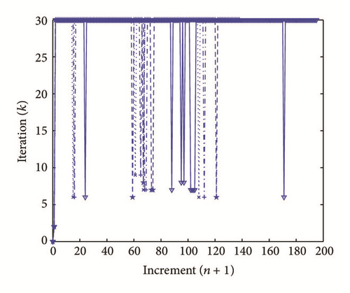
Evolution of the number of iterations (k) for each increment (n) obtained with the new iterative numerical continuation algorithm (blue line; see (26)–(30) with Θ = Θ1) for Example 1 (E1) with the parameters α = 50 and β = −100 and for different values of the parameter γ: (i) γ = 1 (blue solid line with upward-pointing triangles); (ii) γ = 1.4 (blue dotted line with pentagrams); (iii) γ = 1.5 (blue dash-dot line with plus signs); (iv) γ = 1.6 (blue dashed line with crosses).
Details are in the caption following the image
Evolution of the approximate solutions () obtained with the new iterative numerical continuation algorithm (see (26)–(30) with Θ = Θ1) and compared with the exact solution (black solid line) for Example 2 (E2) with the following parameters: (i) α = 1000, β = 500, and γ = 2 (blue solid line with circles); (ii) α = 1000, β = 5000, and γ = 2 (green solid line with squares); (iii) α = 1000, β = 30, and γ = 2 (magenta solid line with diamonds); (iv) α = 1000, β = 50000, and γ = 2 (red solid line with upward-pointing triangles); (v) α = 3000, β = 10, and γ = 2 (cyan solid line with downward-pointing triangles).
Details are in the caption following the image
Evolution of the residue error of the function (), the approximation error of displacement U (), and mechanical load λ () obtained with the new iterative numerical continuation algorithm (see (26)–(30) with Θ = Θ1) for Example 2 (E2) with the following parameters: (i) α = 1000, β = 500, and γ = 2 (blue solid line with circles); (ii) α = 1000, β = 5000, and γ = 2 (green solid line with squares); (iii) α = 1000, β = 30, and γ = 2 (magenta solid line with diamonds); (iv) α = 1000, β = 50000, and γ = 2 (red solid line with upward-pointing triangles); (v) α = 3000, β = 10, and γ = 2 (cyan solid line with downward-pointing triangles).
Details are in the caption following the image
Evolution of the approximate solutions of first-order partial derivatives associated with the displacement U () and the mechanical load λ () obtained with the new iterative numerical continuation algorithm (see (26)–(30) with Θ = Θ1) for Example 2 (E2) with the following parameters: (i) α = 1000, β = 500, and γ = 2 (blue solid line with circles); (ii) α = 1000, β = 5000, and γ = 2 (green solid line with squares); (iii) α = 1000, β = 30, and γ = 2 (magenta solid line with diamonds); (iv) α = 1000, β = 50000, and γ = 2 (red solid line with upward-pointing triangles); (v) α = 3000, β = 10, and γ = 2 (cyan solid line with downward-pointing triangles).
Details are in the caption following the image
Evolution of the number of iterations (k) for each increment (n) obtained with the new iterative numerical continuation algorithm (see (26)–(30) with Θ = Θ1) for Example 2 (E2) with the following parameters: (i) α = 1000, β = 500, and γ = 2 (blue solid line with circles); (ii) α = 1000, β = 5000, and γ = 2 (green solid line with squares); (iii) α = 1000, β = 30, and γ = 2 (magenta solid line with diamonds); (iv) α = 1000, β = 50000, and γ = 2 (red solid line with upward-pointing triangles); (v) α = 3000, β = 10, and γ = 2 (cyan solid line with downward-pointing triangles).
Details are in the caption following the image
Evolution of the approximate solutions () obtained with the new iterative numerical continuation algorithm (cyan line; see (26)–(30) with Θ = Θ1) and compared with the exact solution (black solid line) for Example 2 (E2) with the parameters α = 3000 and β = 10 and for different values of the parameter γ: (i) γ = 2 (cyan solid line with downward-pointing triangles); (ii) γ = 4 (cyan dotted line with pentagrams); (iii) γ = 5 (cyan dash-dot line with plus signs); (iv) γ = 6.65 (cyan dashed line with crosses).
Details are in the caption following the image
Evolution of the residue error of the function (), the approximation error of displacement U (), and mechanical load λ () obtained with the new iterative numerical continuation algorithm (cyan line; see (26)–(30) with Θ = Θ1) for Example 2 (E2) with the parameters α = 3000 and β = 10 and for different values of the parameter γ: (i) γ = 2 (cyan solid line with downward-pointing triangles); (ii) γ = 4 (cyan dotted line with pentagrams); (iii) γ = 5 (cyan dash-dot line with plus signs); (iv) γ = 6.65 (cyan dashed line with crosses).
Details are in the caption following the image
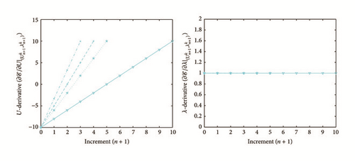
Evolution of the approximate solutions of first-order partial derivatives associated with the displacement U () and the mechanical load λ () obtained with the new iterative numerical continuation algorithm (cyan line; see (26)–(30) with Θ = Θ1) for Example 2 (E2) with the parameters α = 3000 and β = 10 and for different values of the parameter γ: (i) γ = 2 (cyan solid line with downward-pointing triangles); (ii) γ = 4 (cyan dotted line with pentagrams); (iii) γ = 5 (cyan dash-dot line with plus signs); (iv) γ = 6.65 (cyan dashed line with crosses).
Details are in the caption following the image
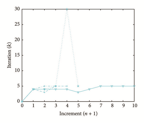
Evolution of the number of iterations (k) for each increment (n) obtained with the new iterative numerical continuation algorithm (cyan line; see (26)–(30) with Θ = Θ1) for Example 2 (E1) with the parameters α = 3000 and β = 10 and for different values of the parameter γ: (i) γ = 2 (cyan solid line with downward-pointing triangles); (ii) γ = 4 (cyan dotted line with pentagrams); (iii) γ = 5 (cyan dash-dot line with plus signs); (iv) γ = 6.65 (cyan dashed line with crosses).
Details are in the caption following the image
Evolution of the approximate solutions () obtained with the new iterative numerical continuation algorithm (see (26)–(30) with Θ = Θ1) and compared with the exact solution (black solid line) for Example 3 (E3) with the following parameters: (i) α = 10000, β = 200, and γ = 20 (blue solid line with circles); (ii) α = 10000, β = 1000, and γ = 20 (green solid line with squares); (iii) α = 10000, β = 500, and γ = 20 (magenta solid line with diamonds); (iv) α = 1000, β = 5000, and γ = 20 (red solid line with upward-pointing triangles); (v) α = 100, β = 5000, and γ = 20 (cyan solid line with downward-pointing triangles).
Details are in the caption following the image
Evolution of the residue error of the function (), the approximation error of displacement U (), and mechanical load λ () obtained with the new iterative numerical continuation algorithm (see (26)–(30) with Θ = Θ1) for Example 3 (E3) with the following parameters: (i) α = 10000, β = 200, and γ = 20 (blue solid line with circles); (ii) α = 10000, β = 1000, and γ = 20 (green solid line with squares); (iii) α = 10000, β = 500, and γ = 20 (magenta solid line with diamonds); (iv) α = 1000, β = 5000, and γ = 20 (red solid line with upward-pointing triangles); (v) α = 100, β = 5000, and γ = 20 (cyan solid line with downward-pointing triangles).
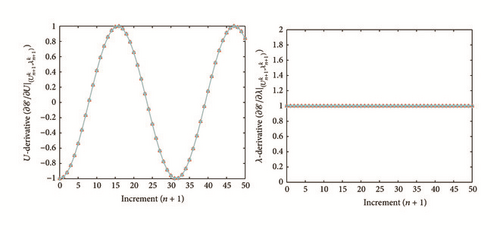
Details are in the caption following the image
Evolution of the approximate solutions of first-order partial derivatives associated with the displacement U () and the mechanical load λ () obtained with the new iterative numerical continuation algorithm (see (26)–(30) with Θ = Θ1) for Example 3 (E3) with the following parameters: (i) α = 10000, β = 200, and γ = 20 (blue solid line with circles); (ii) α = 1000, β = 1000, and γ = 20 (green solid line with squares); (iii) α = 10000, β = 500, and γ = 20 (magenta solid line with diamonds); (iv) α = 1000, β = 5000, and γ = 20 (red solid line with upward-pointing triangles); (v) α = 100, β = 5000, and γ = 20 (cyan solid line with downward-pointing triangles).
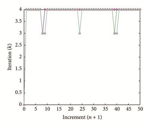
Details are in the caption following the image
Evolution of the number of iterations (k) for each increment (n) obtained with the new iterative numerical continuation algorithm (see (26)–(30) with Θ = Θ1) for Example 3 (E3) with the following parameters: (i) α = 10000, β = 200, and γ = 20 (blue solid line with circles); (ii) α = 10000, β = 1000, and γ = 20 (green solid line with squares); (iii) α = 10000, β = 500, and γ = 20 (magenta solid line with diamonds); (iv) α = 1000, β = 5000, and γ = 20 (red solid line with upward-pointing triangles); (v) α = 100, β = 5000, and γ = 20 (cyan solid line with downward-pointing triangles).
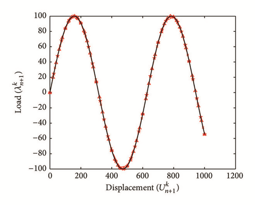
Details are in the caption following the image
Evolution of the approximate solutions () obtained with the new iterative numerical continuation algorithm (red line; see (26)–(30) with Θ = Θ1) and compared with the exact solution (black solid line) for Example 3 (E3) with the parameters α = 1000 and β = 5000 and for different values of the parameter γ: (i) γ = 20 (red solid line with upward-pointing triangles); (ii) γ = 25 (red dotted line with pentagrams); (iii) γ = 50 (red dash-dot line with plus signs); (iv) γ = 33 (red dashed line with crosses).
Details are in the caption following the image
Evolution of the residue error of the function (), the approximation error of displacement U (), and mechanical load λ () obtained with the new iterative numerical continuation algorithm (red line; see (26)–(30) with Θ = Θ1) for Example 3 (E3) with the parameters α = 1000 and β = 5000 and for different values of the parameter γ: (i) γ = 20 (red solid line with upward-pointing triangles); (ii) γ = 25 (red dotted line with pentagrams); (iii) γ = 50 (red dash-dot line with plus signs); (iv) γ = 33 (red dashed line with crosses).
Details are in the caption following the image
Evolution of the approximate solutions of first-order partial derivatives associated with the displacement U () and the mechanical load λ () obtained with the new iterative numerical continuation algorithm (red line; see (26)–(30) with Θ = Θ1) for Example 3 (E3) with the parameters α = 1000 and β = 5000 and for different values of the parameter γ: (i) γ = 20 (red solid line with upward-pointing triangles); (ii) γ = 25 (red dotted line with pentagrams); (iii) γ = 50 (red dash-dot line with plus signs); (iv) γ = 33 (red dashed line with crosses).
Details are in the caption following the image
Evolution of the number of iterations (k) for each increment (n) obtained with the new iterative numerical continuation algorithm (red line; see (26)–(30) with Θ = Θ1) for Example 3 (E3) with the parameters α = 1000 and β = 5000 and for different values of the parameter γ: (i) γ = 20 (red solid line with upward-pointing triangles); (ii) γ = 25 (red dotted line with pentagrams); (iii) γ = 50 (red dash-dot line with plus signs); (iv) γ = 33 (red dashed line with crosses).

In the light of all numerical results obtained in Sections 4.3.1 and 4.3.2, the new iterative numerical continuation algorithm is a relatively accurate, efficient, and robust method that allows passing specific critical points and providing suitable approximate solutions associated with parameterized scalar nonlinear equations.
5. Conclusion

The present paper is devoted to a new iterative numerical continuation procedure for approximating the solutions associated with parameterized scalar nonlinear equations. Coupled with a modified Newton-type method and a stationary numerical technique, the presented algorithm is capable of providing satisfactory numerical solutions for scalar nonlinear equations using one control parameter. Through some illustrative examples, the predictive abilities of this new algorithm are tested, assessed, and discussed.

Competing Interests

The author declares that he has no competing interests.

    The full text of this article hosted at iucr.org is unavailable due to technical difficulties.