Numerical Simulation of Barite Sag in Pipe and Annular Flow
Abstract
With the ever increasing global energy demand and diminishing petroleum reserves, current advances in drilling technology have resulted in numerous directional wells being drilled as operators strive to offset the ever-rising operating costs. In as much as deviated-well drilling allows drillers to exploit reservoir potential by penetrating the pay zone in a horizontal, rather than vertical, fashion, it also presents conditions under which the weighting agents can settle out of suspension. The present work is categorized into two parts. In the first part, governing equations were built inside a two-dimensional horizontal pipe geometry and the finite element method utilized to solve the equation-sets. In the second part, governing equations were built inside a three-dimensional horizontal annular geometry and the finite volume method utilized to solve the equation-sets. The results of the first part of the simulation are the solid concentration, mixture viscosity, and a prediction of the barite bed characteristics. For the second part, simulation results show that the highest occurrence of barite sag is at low annular velocities, nonrotating drill pipe, and eccentric drill pipe. The CFD approach in this study can be utilized as a research study tool in understanding and managing the barite sag problem.
1. Introduction
With the ever increasing global energy demand and diminishing petroleum reserves, recent advances in drilling technology have resulted in numerous directional wells being drilled as operators strive to offset the ever-rising operating costs. Deviated-well drilling allows operators to exploit reservoir potential by penetrating the pay zone in a horizontal, rather than vertical, fashion. With consideration of eliminating drilling problems such as stuck pipe, torque and drag, wellbore instability, and low rates-of-penetration, these wells are being drilled increasingly with invert-emulsion drilling fluids.
In the drilling industry, the term “barite sag” refers to the settling of weighting materials in drilling fluids under flowing (pumping) or no flowing (no pumping) conditions. In as much as there exist substitutes such as iron titanium oxide, calcium carbonate, and manganese tetra oxide, barite is used extensively since it provides high density with wide accessibility and favourable economics and it is ecofriendly. Notwithstanding mentioning, the API 13D defines barite sag (in the field) as the change in drilling fluid density observed when circulating bottoms-up; it is almost always characterized by drilling fluid having a density below nominal, being followed by drilling fluid densities above nominal, and being circulated out of the annulus [1].
Modelling and simulation studies employ a combination of both mathematical formulations and numerical techniques where the governing equations for a problem definition are solved by either writing a computer program (code) following a discretization scheme such as finite difference method (FDM) or using CFD software to obtain a solution following a numerical method such as finite element method (FEM) or finite volume method (FVM). The solution obtained is referred to as a numerical solution since a particular numerical procedure is followed and the whole process generally called numerical simulation. Numerous researchers have studied the barite sag phenomenon by employing modelling and simulation studies.
Paslay et al. [2] presented a fundamental theoretical effort to describe dynamic sag in drilling fluids by considering the behaviour of a system of particles in a non-Newtonian Bingham fluid. The authors employed continuum mechanics to develop a model of dynamic sag in an inclined annulus in terms of the fluid and particle properties. They focused on the period when pumping and rotation are stopped. They indicated that the particles settle for a few minutes immediately following the cessation of rotation and pumping when the gelling properties of the stationary drilling fluid have not been fully recovered. The analysis upon which the results were deduced is laminar flow and the predictions appeared to be consistent with the operational guidelines presented by Dye et al. [3].
Nguyen et al. [4] described a fundamental mathematical approach (based mainly on the continuum methodology) to examine the sedimentation of barite particles in shear flow of Newtonian fluids; they established a numerical method to solve four partial differential equation-sets describing dynamic barite sag in pipe flow of Newtonian fluids. They calculated the concentration of solid in both the axial and radial directions as a function of time by using an explicit FDM method.
Hashemian et al. [6, 7] performed a study on barite sag by (1) modelling of laminar flow of non-Newtonian fluid in annulus to obtain velocity profile and (2) consideration of the solid particles in the fluid to predict the particle traveling path and time. The simulation was based on a proposed particle tracking method called “Particle Elimination Technique.” It is important to note that the simulation approach employed is much dependent on a parallel experimental study. The estimation of unknown parameters (, mass rate of barite bed back to suspension, , average velocity of the barite bed, and µ, viscosity of the barite bed) that are input parameters in the simulation is based on the experimental results. This is rather a shortcoming of this approach as it cannot be performed independently and later make a comparison with experimental data.
Kulkarni et al. [8] presented a novel method of predicting real-time sag behaviour in the wellbore by employing a comprehensive computational approach to model the sag behaviour in wellbores using fluids composition (i.e., weight-material (barite) size/concentration and oil-water ratio)/properties (i.e., rheology) and wellbore geometry (i.e., inclination and diameter)/operating conditions (i.e., temperature, pressure, and time for which the fluid is uncirculated) information. The model developed was referred to as the wellbore sag model (WSM). The authors reported that, generally, the WSM captured the appropriate characteristics of the fluids and successfully predicted their respective sag behaviour.
The objective of this paper is to present an entirely independent numerical simulation study on barite sag in pipe and annular sections by employing CFD. Additionally, a CFD-DEM approach, based on preliminary results, is proposed for future research on the study of barite sag in annular sections.
2. Mathematical Approach
The mathematical approach is in two parts. In the first part, the governing equations are built inside a two-dimensional horizontal pipe geometry and the finite element method (FEM) utilized to solve the equation-sets, for studying the solid concentration distribution of a solid-liquid system in pipe flow. In the second part, governing equations are built inside a three-dimensional horizontal annular geometry and the finite volume method (FVM) utilized to solve the equation-sets, for studying the barite sag phenomenon in an annulus under flow conditions.
2.1. Horizontal Pipe Section
Description of the Eulerian-Eulerian approach to study the solid concentration distribution in a pipe in shear flow of a solid-liquid system: This model assumes that solid concentration only changes in the axial and lateral directions. In addition, the model is developed under laminar flow conditions.
2.1.1. Mass Balance
In order to control the mass balance of the two phases, the Euler-Euler model interface solves (4) together with (5). Equation (4) is used to compute the volume fraction of the dispersed phase, and (5) is used to compute the mixture pressure.
2.1.2. Momentum Balance
2.1.3. Dispersed Phase Viscosity
2.1.4. Interphase Momentum Transfer
2.1.5. Dilute Flows
2.1.6. Solid Pressure
2.2. Horizontal Annular Section
Description of the 3D model employed to study the behaviour of barite particles in an annulus based on the CFD approach is as follows.
2.2.1. Governing Equations for Fluid Flow
The local averaged Navier-Stokes equations describe the 3D equations of motion of viscous, unsteady, and incompressible fluid phase.
2.2.2. Governing Equations for Particle Flow
(I) Dispersed Phase Modelled as Lagrangian Phase
Mass Transfer. The rate of mass transfer to a single particle from the continuous phase is .
(b) Drag Coefficient. The Schiller-Naumann correlation [14] is suitable for spherical solid particles (and liquid droplets and small-diameter bubbles). For a viscous continuous phase, the correlation is as defined in (18).
Momentum Transfer. The rate of momentum transfer to a single particle from the continuous phase is , where FS is as defined in (33a).
Boundary Interface Mode. It is important to formulate the Lagrangian phase boundary interaction mode [13].
(II) Dispersed Phase Modelled as DEM Particles. The detailed description is shown in the appendix.
3. Model Configuration
3.1. 2D Model: Horizontal Pipe Section
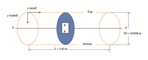
For the physical model of a horizontal pipe section with ID 0.0508 m (2 in.) and length 3.65 m (12 ft) see Figure 1. For the discretized representation of the computational domain which the physics solvers use to provide a numerical solution, the mesh is shown in Figure 2. Table 1 lists the inputs used in the 2D configuration. Additionally, the assumptions and boundary conditions are listed below.
| Parameter | Variable | Value | Units |
|---|---|---|---|
| Diameter of pipe | DP | 0.0508 (2) | m (in.) |
| Length of pipe | L | 3.65 (12) | m (ft.) |
| Fluid inlet velocity | uf | 0.1556 (30.64) | m/s (ft/min) |
| Viscosity of liquid | μL | 0.062 (62) | Pa·s (cP) |
| Density of liquid | ρL | 898.78 (7.5) | kg/m3 (lbm/gal) |
| Density of solid | ρs | 4198.92 (35) | kg/m3 (lbm/gal) |
| Diameter of solid | ds | 0.000025 (25) | m (µm) |
| Initial concentration of the solid | Co | 0.067 | |
| Deviation angle | θ | 90 | ° (from vertical) |
| Number of CFD elements | 63,790 | ||
| CFD time-step | ΔtCFD | 0.1 | s |
| Physical time simulated | tend | 36 | s |

- (i)
Every single phase of the mixture behaves as if it was a lone phase, with the exception of the case when interacting with the other phase.
- (ii)
The equations of motion describing the mixture are similarly those for a single phase and are the consequence of the summation motion equations for the individual phases over all phases.
- (iii)
Flow of the liquid phase is in one direction (that is, axial), whereas that of the solid phase is in two directions (both axial and radial).
- (iv)
The liquid and solid densities are constant; in other words, phases are incompressible.
- (v)
There is no consideration of Brownian motion.
- (vi)
There is no particle interaction arising from collisions and friction between the particles. Thus, solid pressure is neglected.
- (vii)
Wall effects are neglected.
- (viii)
Isothermal and laminar flow are considered.
- (i)
No-slip condition at the walls.
- (ii)
Inlet boundary conditions, that is, velocity inlet.
- (iii)
Outlet boundary conditions, that is, pressure outlet.
3.2. 3D Model: Horizontal Annular Section
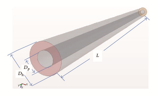
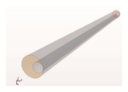
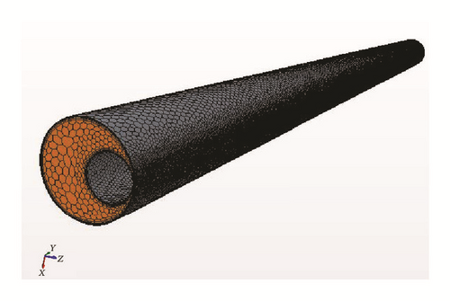
The physical model is an annular test section as depicted in Figure 3. Figure 3(a) shows the physical model for a concentric annular section whereas Figure 3(b) depicts an eccentric annular section. For the discretized representation of the computational domain which the physics solvers use to provide a numerical solution, the mesh is shown in Figure 4. Table 2 lists the inputs used in the 3D configuration. Additionally, the assumptions and boundary conditions are listed below.
| Parameter | Variable | Value | Units |
|---|---|---|---|
| Drill string length | L | 1.8288 (6) | m (ft.) |
| Pipe diameter | Dp | 0.0508 (2) | m (inch) |
| Hole diameter | Dh | 0.1016 (4) | m (inch) |
| Angle of inclination | θ | 0–90 | ° (degrees) |
| Fluid inlet velocity | uf | 0.1524 (30)–0.762 (150) | m/s (ft./min) |
| Dynamic viscosity | μf | ||
| Density of liquid | ρf | 958.61 (8.0) | kg/m3 (ppg) |
| Fluid behaviour index | n | 0.44 | — |
| Consistency index | K | 0.63 (1.316) | Pa·s n (lbfs n/100 ft2) |
| Drill pipe rotation speed | ωdrillpipe | 0–100 | rpm |
| Eccentricity ratio | e | 0, 1 | — |
| Shape of particles | spherical | ||
| Particle diameter | dp | 0.0000249 (24.9) | m (microns) |
| Particle density (dry density) | ρp | 4193.92 (35.0) | kg/m3 (ppg) |
| Coefficient of restitution | ϵ | 1.0 | — |
| Number of CFD cells | 84,102 | ||
| CFD time-step | ΔtCFD | 0.01 | s |
| Physical time simulated | tend | 36 | s |

- (i)
Flow of the liquid phase is in one direction (that is, axial), whereas that of the solid phase is in two directions (both axial and radial).
- (ii)
The phases are incompressible; that is, the densities of the solid and liquid are constant.
- (iii)
Interaction forces such as shear lift force, drag force, and pressure gradient force exist between the liquid and solid phase.
- (iv)
Solid particles are spherical.
- (v)
Solid particles are considered as Lagrangian phases.
- (vi)
The liquid phase is a generalized power law (non-Newtonian) fluid.
- (vii)
Isothermal and laminar flow are considered.
- (i)
No-slip condition at the walls.
- (ii)
Inlet boundary conditions, that is, velocity inlet.
- (iii)
Outlet boundary conditions, that is, pressure outlet.
4. Results and Discussion
4.1. 2D Model: Horizontal Pipe Section
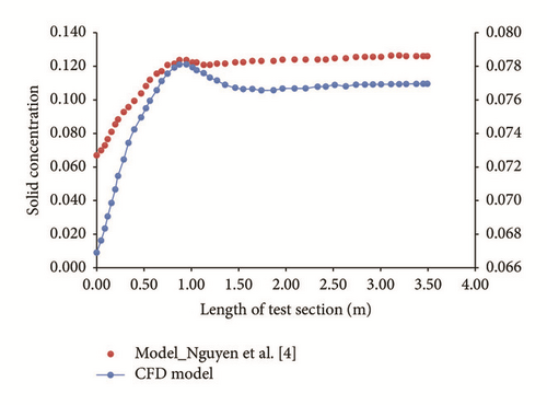
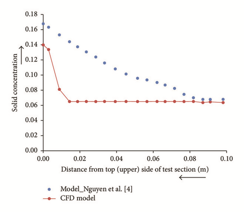
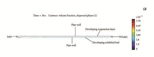
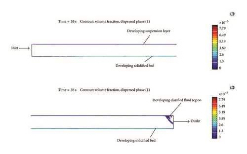
The 2D-CFD model is compared with the mathematical model of Nguyen et al. [4]. The variation of solid concentration in both the axial and lateral (radial) directions is shown in Figures 5 and 6 for an initial concentration of solid, Co = 0.067; inlet fluid velocity, u = 0.1556 m/s; and deviation angle, θ = 90° (from vertical). Comparison between the CFD model and the mathematical model shows a reasonable match in the observed trend for the solid concentration distribution in both the axial and radial directions. However, it should be noted that there is variance in the observed magnitude of solid concentration. This is majorly attributed to the difference in the time taken to achieve the solution; for example, a simulation time of 1 s is equivalent to a physical time of many hours (or days). This is a plausible explanation as sufficient circulating time is required, in practice, to achieve considerable sedimentation (sag). The other possible reason(s) for the apparent discrepancy is/are unknown at the time. Note that the minimum time for the fluid to flow from inlet to outlet at a velocity of 0.1556 m/s is 23.5 s.
4.1.1. Solid Concentration Distribution
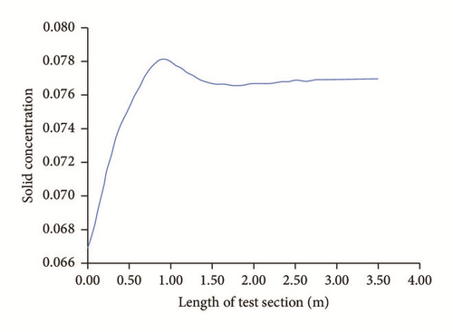
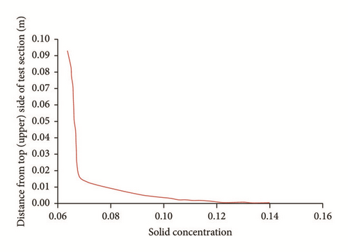
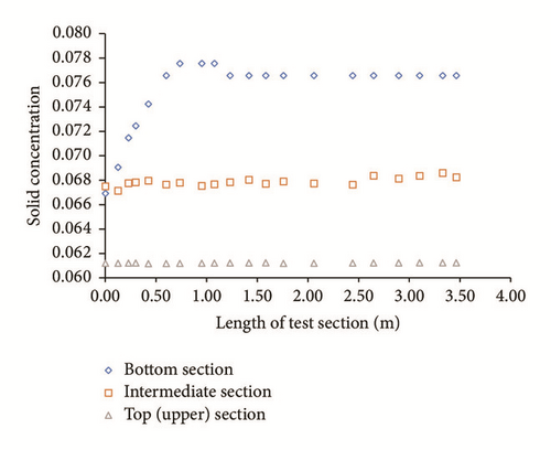
Initially, when t = 0 seconds, the solid concentration is Co = 0.067. As time progresses, the concentration of solid increases in both the axial and lateral directions. The major increase in the concentration of solid occurs at the bottom of the pipe. Figure 7 displays that the concentration of solid increases rapidly near the inlet of the test section and thereafter appears to be constant. The concentration of solid at the upper section of the pipe does not decrease with time; it is nearly equal to the initial concentration of the solid (Figure 8). Additionally, Figure 8 shows that major increase in concentration of solid occurs at the bottom of the pipe.
4.1.2. Barite Bed Characteristics
For low annular velocities (i.e., 0.1556 m/s), there is rapid formation of a barite bed at the bottom (lower) section of the pipe. The concentration of solid in this bed is not much greater than the concentration of solid in the fluid, which flows in the top (upper) side of the pipe. Put differently, the bed is actually the fluid with a greater concentration of solid and can be easily removed. This layer is what is referred to as the fluidized bed (see Figure 9, the intermediate section). As time progresses, the bed gets compacted and comes to be more solid. Note that the bed is called a “solidified bed” (Figure 9, the bottom section) when it has been compacted in a time period and cannot be dispatched by only raising annular velocity without initiating pipe rotation.

4.1.3. Mixture Viscosity
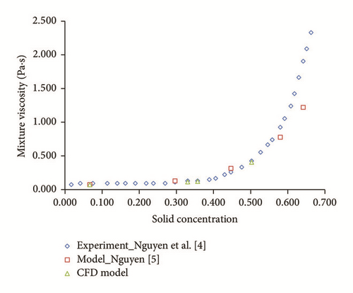
The relationship between continuous phase, dispersed phase, and mixture viscosity follows the correlations presented in (14a)–(14c). The influence of mixture viscosity on barite sedimentation in the pipe section is depicted in Figure 12. The outcomes of the CFD model show that the mixture viscosity is constant and satisfies Einstein’s formula. This is in agreement with the experimental and modelling data of Nguyen et al. [4] and Nguyen [5], up to a solid concentration of less than or equal to 0.4. Beyond a solid concentration of 0.4, the viscosity is a function of solid concentration.
4.2. 3D Model: Horizontal Annular Section
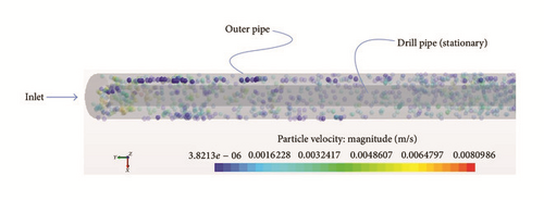
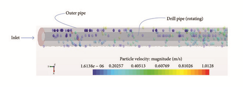
The minimum flow time from inlet to outlet at a velocity of 0.1524 m/s (lowest annular velocity) is 12 s and 2.4 s for a velocity of 0.762 m/s (highest annular velocity). The visualization of barite accumulation clearly illustrates the tendency for the particles to aggregate on the bottom (lower) side of the test section (particularly in the case of an eccentric annulus). This is for the case of a low annular velocity, in this case 0.1524 m/s (30 ft/min) with a stationary drill pipe. The redistribution of barite particles into the fluid stream, at a low annular velocity, is due to rotation of the drill pipe (Figure 13). The simulation outcome is a reasonable match with the experimental observations of Hashemian et al. [6, 7].
4.2.1. Influence of Drill Pipe Rotation on Barite Accumulation for a Concentric Annulus
Particles (barite particles) are injected into the fluid stream, at the inlet, at a mass flow rate of 0.055 kg/s. This configuration simulates the case of high particle concentration (i.e., αP > 10−4). The inlet fluid velocity is 0.1524 m/s (in this case, the lowest annular velocity). Figure 14 shows the barite particle distribution at this low annular velocity and stationary drill pipe for a horizontal concentric annular test section. As can be observed from the sectional views on the right, barite accumulation in a concentric annulus is rather uniform (Figure 14(a)) and only has a slight nonuniform distribution (Figure 14(b)). Therefore, barite accumulation in a horizontal concentric annulus results into a smaller reduction in circulating drilling fluid density. Figure 15 shows the influence of drill pipe rotation at a low annular velocity on the barite accumulation in a horizontal concentric annulus. Observations from the sectional views on the right indicate that drill pipe rotation results into a uniform distribution of the barite particles in the concentric annular section. Overall, this has a slight effect on the barite accumulation. The simulation outcome is a reasonable match with the experimental observations of Hashemian et al. [6, 7].


4.2.2. Combined Effect of High Annular Velocity and Drill Pipe Rotation on Barite Accumulation for a Concentric Annulus
Particles (barite particles) are injected into the fluid stream, at the inlet, at a particle flow rate which defines both the period of injection and the injection velocity. Additionally, this configuration simulates the case of low particle concentration (i.e., αP < 10−4). The inlet fluid velocity is 0.762 m/s and drill pipe rotation speed is 50 rpm.
Initiated at the start of circulation: Figure 16 shows the barite particle behaviour in a horizontal annulus at a high inlet fluid velocity and drill pipe rotation. As can be observed, there is no tendency for barite accumulation in the test section. Even for the particles that are in the lower bottom, they are at a high velocity and thus there is no possibility for sedimentation. The simulation outcome is a reasonable match with the experimental observations of Hashemian et al. [6, 7]. Additionally, Figure 17 shows the particle tracks coloured by the velocity of particles. As can be observed, the particles further away from the inlet are at a higher velocity than the overall particles in the annular section, still indicating no possibility of barite accumulation.


4.2.3. Combined Effect of High Annular Velocity and Drill Pipe Rotation on Barite Accumulation for an Eccentric Annulus
Particles (barite particles) are injected into the fluid stream, at the inlet, at a particle flow rate which defines both the period of injection and the injection velocity. Additionally, this configuration simulates the case of low particle concentration (i.e., αP < 10−4). The inlet fluid velocity is 0.762 m/s and drill pipe rotation speed is 50 rpm.
Initiated at the start of circulation: Figure 18 shows the barite particle behaviour in a horizontal annulus at a high inlet fluid velocity and drill pipe rotation. As can be observed, almost all particles in the test section, slightly further from the inlet, are at a relatively uniform higher velocity. In contrast to Figure 16(a), the combined effect of high annular velocity and rotation of drill pipe has a pronounced effect on barite accumulation in the eccentric scenario than in the concentric scenario.
5. Limitations and Further Development
- (i)
The 2D model configuration for the horizontal pipe does not account for pipe rotation. Additionally, the influence of mean velocity on dynamic barite sag is not accounted for.
- (ii)
The 3D model configuration for the horizontal annulus does not account for different shapes and sizes of particles as it assumes uniform spherical particles. Different particle shapes and sizes can be introduced by employing different particle-shape models in the simulation and then observing the sag tendency.
- (iii)
In the 3D model, only a qualitative analysis of the results is considered. At low particle concentrations, the quantitative results are comparable to those available in published literature and at very high particle concentrations; the model suffers from a convergence problem and thus does not produce reasonable results. Therefore, there is a need to perform a convergence improvement study so as to improve on the accuracy of the results and aid in the quantitative analysis of the results.
- (iv)
In both models, no inclination angle other than 90° is considered. Inclination angles between 30° and 90° can be introduced in the simulation and the resulting sag tendency observed and analysed.
- (v)
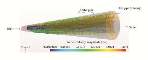
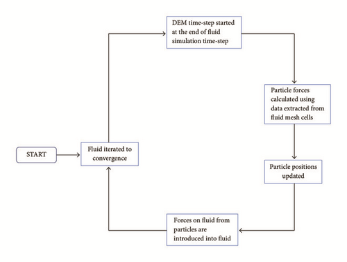
In the 3D model, based on the CFD-DEM approach, only a theoretical background for the governing equations (see the appendix) is provided and one stage of simulation successfully performed (see Figure 19); the implementation scheme employed is depicted in Figure 20. A complete simulation can be performed by using the implementation scheme in Figure 20 or Figure 21 to investigate the different aspects of barite sag under influencing factors, such as annular velocity, drill pipe rotation speed, and eccentric drill pipe.


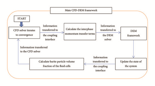
Nevertheless, the 3D model developed above, to the authors’ knowledge, is the first attempt to perform an independent numerical simulation to investigate dynamic barite sag in an annular section. Furthermore, the model based on the CFD-DEM approach is the first attempt to propose the use of the CFD-DEM method for the investigation of barite sag behaviour, keeping in mind that the system is a liquid-solid flow. Past researchers [15–18] have employed this approach in the study and analysis of other systems, but only considering gas-solid flows. The only exception is Zhao and Shan [19] and Akhshik et al. [20] who performed simulation of the behaviour of fluid-particle interactions for applications relevant to mining and geotechnical engineering [19] and the investigation of the effect of drill pipe rotation on cuttings transport behaviour [20].
6. Conclusions
A numerical simulation approach has been undertaken to investigate the different aspects of barite sag behaviour under influencing factors, such as annular velocity, drill pipe rotation speed, and eccentric drill pipe, as well as the rheology of drilling fluid, that is, Newtonian and non-Newtonian fluid. For the Newtonian fluid case, governing equations were built inside a 2D horizontal pipe geometry and the finite element method (FEM) utilized to solve the equation-sets whereas for the non-Newtonian fluid case, the governing equations were built inside a 3D horizontal annular geometry and the finite volume method (FVM) utilized to solve the equation-sets. Furthermore, it is worth noting that the drill pipe motion is modelled as a grid flux in the convective term, instead of a body force due to system rotation in the momentum equations.
The 2D-CFD model shows that the concentration of solid increases with time at the bottom (lower) section of the pipe. For a Newtonian fluid, which has viscosity of 0.062 Pa·s, the CFD model results indicate that, at low fluid inlet velocity (i.e., 0.1556 m/s), there is rapid formation of a barite bed at the bottom (lower) section of the pipe. Additionally, the model results show that there exist three layers during the sedimentation of barite particles in the pipe: the clarified fluid layer (i.e., the fluid that flows upward), the fluidized bed, and the solidified bed layer. There exists a critical solid concentration below which mixture viscosity is independent of solid concentration and beyond which the converse is true.
- (i)
For the case of low annular velocity (i.e., 0.1524 m/s), drill pipe rotation serves to disturb the apparent barite bed and redistribute the barite particles back into the flow stream.
- (ii)
The effect of drill pipe rotation has a pronounced effect for the eccentric annulus compared to the concentric scenario.
- (iii)
The combined effect of high annular velocity (i.e., 0.762 m/s) and drill pipe rotation (i.e., 50 rpm) results in a tremendous reduction in the barite sag occurrence. Still, the effect is more pronounced for the eccentric annulus than the concentric scenario.
- (iv)
Maintaining the drilling fluid circulation at a high annular velocity and with rotating drill pipe ensures that no barite sag occurs.
Nomenclature
-
- CFD:
-
- Computational fluid dynamics
-
- DEM:
-
- Discrete element method
-
- FDM:
-
- Finite difference method
-
- FEM:
-
- Finite element method
-
- FVM:
-
- Finite volume method
-
- 2D:
-
- 2-dimensional
-
- 3D:
-
- 3-dimensional
-
- Re:
-
- Reynolds number
-
- aT:
-
- Temperature shift factor
-
- e:
-
- Eccentricity ratio
-
- Cd:
-
- Drag coefficient
-
- L:
-
- Length of pipe/drill string length
-
- d:
-
- Diameter
-
- Dp:
-
- Diameter of pipe
-
- Dh:
-
- Diameter of hole
-
- p:
-
- Pressure
-
- ρ:
-
- Density
-
- μ:
-
- Viscosity
-
- α:
-
- Volume fraction
-
- :
-
- Shear rate
-
- n:
-
- Power law exponent
-
- K:
-
- Consistency factor
-
- θ:
-
- Deviation/inclination angle
-
- ϵ:
-
- Coefficient of restitution
-
- ω:
-
- Angular velocity.
Subscripts
-
- n:
-
- Normal
-
- t:
-
- Tangential
-
- s:
-
- Solid
-
- p:
-
- Particle
-
- L:
-
- Liquid
-
- f:
-
- Fluid.
Conflicts of Interest
The authors declare that they have no conflicts of interest.
Acknowledgments
This work is financially supported by the Fundamental Research Funds for the Central Universities (Grant no. 16CX05019A) and the National Natural Science Foundation of China (Grant no. 51104171).
Appendix
Note that the momentum transfer to the particle from the continuous phase is simply FS. However, when two-way coupling is activated, FS is accumulated over all the parcels and applied in the continuous phase momentum equation.
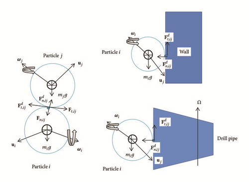
Note that, for particle-wall collisions, the formulas stay the same, but the wall radius and mass are assumed to be Rwall = ∞ and Mwall = ∞, so the equivalent radius is reduced to Req = Rparticle and Mwall = Mparticle.
Pressure Gradient Force. The equation for pressure gradient force is as defined in (35).
DEM Lift Forces. Lift forces in DEM simulations can arise from particle spin, particle shear, or both. Thus, lift forces are taken to mean forces normal to the particle velocity; they are not necessarily forces in the upward direction.
(a) Particle Shear Lift Force. This force applies to a particle moving relative to a fluid where there is a velocity gradient in the fluid orthogonal to the relative motion; it is as defined in (37)–(41).
Note that (A.20) is a 3D version; the 2D equivalent has a term .


