Power Quality Investigation of Distribution Networks Embedded Wind Turbines
Abstract
In recent years a multitude of events have created a new environment for the electric power infrastructure. The presence of small-scale generation near load spots is becoming common especially with the advent of renewable energy sources such as wind power energy. This type of generation is known as distributed generation (DG). The expansion of the distributed generators- (DGs-) based wind energy raises constraints on the distribution networks operation and power quality issues: voltage sag, voltage swell, voltage interruption, harmonic contents, flickering, frequency deviation, unbalance, and so forth. Consequently, the public distribution network conception and connection studies evolve in order to keep the distribution system operating in optimal conditions. In this paper, a comprehensive power quality investigation of a distribution system with embedded wind turbines has been carried out. This investigation is carried out in a comparison aspect between the conventional synchronous generators, as DGs are widely in use at present, and the different wind turbines technologies, which represent the foresightedness of the DGs. The obtained results are discussed with the IEC 61400-21 standard for testing and assessing power quality characteristics of grid-connected wind energy and the IEEE 1547-2003 standard for interconnecting distributed resources with electric power systems.
1. Introduction
Nowadays, power quality (PQ) in the distribution systems has been a research area of exponentially increasing interest because of an increasing concern to both distribution utilities and customers. The increased concern of power quality has resulted in measuring power quality variations and characteristic disturbances for different customer categories. Load switching, system faults, motor starting, load variations, nonlinear loads, intermittent loads, and arc furnaces usually cause power quality disturbances. These cause many electrical disturbances such as voltage sag, swell, harmonic distortions, interruptions, flicker, and unbalance. Power quality assessment is very important for operation of devices in customer side and its issue is also important for the utility companies that are obliged to supply consumers with electrical power of acceptable quality [1–5].
Wind power turbines have, nowadays, increasing penetration levels in power grids for their splendid reserve. The wind turbine can be connected to either a high voltage network, as a wind farm, or distribution systems, as individual turbines. Such power turbines have their own characteristics and operation modes. Consequently, several challenges arise concerning their impacts on the power system profile regarding the power quality issues [6, 7].
Considering the frequent occurrence of power quality problems in the distribution system, in addition to the new trend for using wind turbines as new distributed generators (DGs), the power quality analysis of the distribution system considering different technologies of wind turbines becomes imperatively important. Therefore, in this paper, a comprehensive study of the power quality problems for a considered 15-bus radial distribution system with embedded distributed generators (DGs) has been carried out. Different technologies of the DGs have been considered. The power quality studies are carried out in a comparison aspect between the conventional synchronous generator, as DGs are widely in use at present, and the different wind turbines technologies, which represent the foresightedness of the DGs. The absence of DGs is assumed as a base case for the studies.
This paper is organized as follows. Section 2 describes the considered distribution system component modelling. The steady state voltage profile of the considered system is given in Section 3. Section 4 presents a complete study about voltage sag, voltage swell, and voltage interruption during load variation and system disturbances. Voltage fluctuation and flicker resulting from wind speed variation and pulsating loads are analyzed in Section 5. The harmonic distortion supplied by the wind turbine generators and the nonlinear loads are investigated in Section 6. Section 7 discusses the electrical power losses and the effect of wind turbine output power and connection point on power loss values. Finally, Section 8 summarizes the main conclusions.
2. Configuration of the Considered Distribution System
In this paper, the 15-bus radial distribution system, shown in Figure 1, is considered. All the system data are given in the Appendix. Each of the feeder sections is represented by series RL impedance and the system transformers are modelled by its T-equivalent circuit. In the steady state studies, the loads are represented by constant power models, as is usual in the load flow studies, while in the dynamic studies the loads are represented by constant impedance. The simulation package adopted is the Sim-Power Systems for use with Matlab/Simulink.

The DGs considered in this paper are the conventional synchronous generators, which are widely in use at present, in addition to the wind turbine generators, which represent the foresightedness of the DGs. The wind turbines generators can be classified as fixed speed and variable speed wind turbines generators. The fixed speed induction generator (FSIG) wind turbine is equipped with a squirrel-cage induction generator while the variable speed wind turbines can be either a partially rated converter- or a fully rated converter-based wind turbine. The partially rated converter-based wind turbines are always equipped with a double fed induction generator (DFIG). The fully rated converter-based wind turbine can be equipped with a wound rotor induction generator or a conventional synchronous generator or a permanent magnet synchronous generator (PMSG). The PMSG is the one commonly used for avoiding the field current supply, needed by wound rotor synchronous generators, or because of the reactive power compensation facilities, needed by induction generators. Furthermore, the PMSG removes the need for slip rings.
The following subsections summarize the modelling of all the considered distributed generators.
2.1. Synchronous Generators
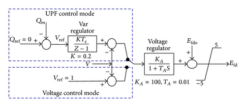
In this paper, the synchronous generator is represented by the eight-order model [8]. There are two different modes of controlling the generator excitation system. One aims to maintain its terminal voltage (constant voltage control mode) while the other one aims to maintain its power factor (constant power factor control mode) [9]. The power factor control mode is usually adopted by independent producers to maximize the active power production. The set points of voltage control and unity power factor control mode are depicted in Figure 2.
2.2. FSIG Wind Turbine
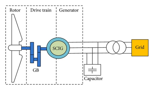
Figure 3 shows the schematic diagram of a fixed speed wind turbine, which consists of three main parts: the rotor, the drive train, and the squirrel-cage induction generator (SCIG). The dynamic models of the rotor and the drive train are given in [10]. The SCIG was represented by the fourth-order state-space model, and its mechanical parts were represented by a second-order system [8]. The generator needed reactive power was locally supplied by capacitors installed at its terminals. The capacitor capacity was adopted equal to 1/3 of the generator rated power [11].
2.3. DFIG Wind Turbine
The basic configuration of the DFIG driven by wind turbine is shown in Figure 4. The DFIG is a wound rotor induction generator, which has the same model of SCIG except that the rotor voltage does not equal zero [12].
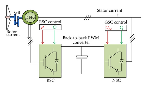
The DFIG is fed from its both stator and rotor sides. The stator is directly connected to the grid while its rotor is connected to the grid through a variable frequency AC/DC/AC converter (VFC). The VFC consists of two four-quadrant insulated-gate bipolar transistor (IGBT) pulse width modulation (PWM) converters connected back-to-back by a DC-link capacitor [13, 14].
In order to deliver an electrical power with constant voltage and frequency to the utility grid for a wide operating range of speed, from subsynchronous to supersynchronous speeds, the power flow between the generator rotor circuit and the grid must be controlled in both magnitude and direction. Connecting the rotor with the grid, via a four-quadrant AC-to-AC converter, enables the decoupling of the control of the generator active and reactive powers. Also, the variable frequency rotor voltage permits the adjustment of the rotor speed to match the optimum operating point at any practical wind speed.
The rotor side converter (RSC) and the network side converter (NSC) control circuits are shown in Figure 5, where the RSC control system consists of two basic control loops for the active and the reactive powers P and Q, respectively. The NSC is used for keeping the DC-link capacitor voltage constant regardless of the magnitude and direction of rotor power as well as controlling the NSC output reactive power especially in case of the grid disturbance.
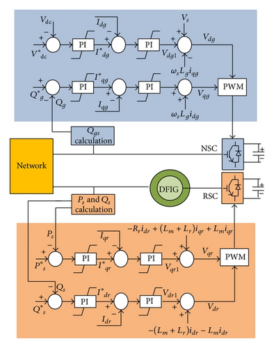
The constant power factor and constant voltage control modes, previously described in the synchronous generator subsection, will be considered with the DFIG. The constant power factor control mode can be adjusted by setting , stator reference reactive power, and , NSC reference reactive power, to zero. On the other side, the voltage control mode can be obtained by adjusting the reactive power reference to obtain a generator terminal voltage of 1 pu.
2.4. PMSG Wind Turbine
The typical configuration of the fully rated converter- (FRC-) based wind turbine is shown in Figure 6. As all the power from the wind turbine is transferred through the power converter, the specific characteristics and dynamics of the wind turbine generator are completely isolated from the power network. Hence, the electrical frequency of the generator may vary as the wind speed changes, while the network frequency remains constant, permitting the generator variable speed operation. Note that rating of the power converter for this wind turbine type is usually more than the generator rated power [14].
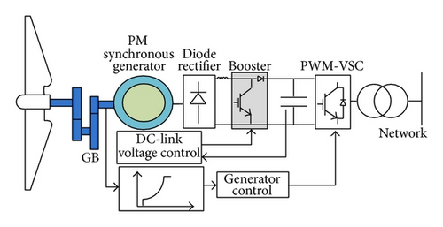
Figure 6 shows the arrangement of the PMSG with an uncontrolled diode-based rectifier as the generator side converter (GSC), DC/DC converter (DC booster), and voltage source converter (NSC) as power electronics controlled converters.
Below rated wind speed, the control objective is to track wind speed to capture and transfer the maximum power to the grid. The generator and rectifier system is uncontrolled. Therefore, the control has to be implemented by the power electronics converters, DC/DC converter (DC booster), and voltage source converter (NSC) [14].
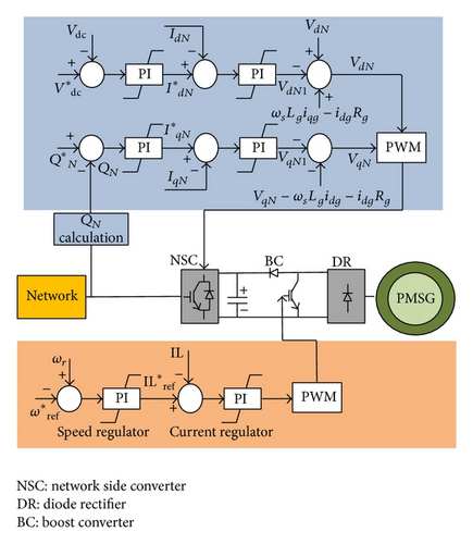
DC/DC converters regulate the DC voltages of generator-rectifier units by varying the switching ratio so that the optimum DC voltage profile is presented at the rectifier terminal for maximum power capture operation. Meanwhile, an appropriate DC voltage is maintained at the DC bus to enable the voltage source inverters to perform the optimal real power transfer and reactive power regulation. A block diagram of the vector control of the network side converter and DC booster is shown in Figure 7.
3. Steady State Voltage Profile Computations
- (i)
no generation and maximum load demand;
- (ii)
maximum generation and maximum load demand;
- (iii)
maximum generation and minimum load demand.
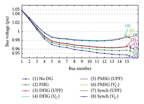
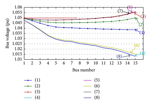
In this paper, it is considered that the minimum load demand corresponds to 10% of the maximum demand, and the allowable steady state voltage regulation is equal to ±5% of the supply voltage.
It is important to note that, considering the case without DG, the substation transformer tapping was adjusted to maintain the voltage values at all the feeder buses within the allowable range for minimum and maximum demands.
- (i)
Some buses voltages will violate the superior limit during minimum demand when the unity power factor (UPF) operating mode is considered for synchronous generator, DFIG, and PMSG.
- (ii)
The performance of FSIG is very close to without DG case; some buses voltages will be below the inferior limit during maximum load demand and above the superior limit during minimum load demand.
- (iii)
If voltage control mode (VC) for synchronous generator, DFIG, and PMSG is employed, then the steady state buses voltages will remain within the allowable range for both maximum and minimum load demands.
3.1. Steady State Voltage Variation due to DG Disconnection
- (i)
Greater values of VI% are obtained when each of the DFIG, PMSG, and synchronous generators is operating under voltage control condition. This essentially means that, using one of these DG types, values of the load buses voltage will be adversely affected after the generator disconnection.
- (ii)
Under the distributor maximum loading condition, the loads buses voltage variation will not be greatly affected after the DG disconnection. This means that the penetration ratio increase of the DG will adversely affect the buses voltage after DG disconnection.
| Generator type | VI% | |
|---|---|---|
| Maximum load | Minimum load | |
| FSIG | 0.043 | 0.642 |
| DFIG | ||
| UPF | 1.089 | 0.743 |
| Voltage control | 2.276 | 1.368 |
| PMSG | ||
| UPF | 1.088 | 0.744 |
| Voltage control | 2.250 | 1.343 |
| Synchronous | ||
| UPF | 1.091 | 0.746 |
| Voltage control | 2.247 | 1.301 |
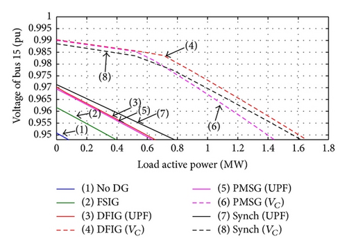
3.2. The Distribution System PL-VL Characteristics considering Different DGs Types
Normally, it is expected that installation of the generators close to the loads can improve the system voltage stability. However, the impact on the voltage stability depends on the reactive power exchange between the connected generator and the network, which is different from distinct DGs technologies.
- (i)
The usage of the DGs, independent of the type, increases the load power margin while maintaining the bus voltage within the admissible limits.
- (ii)
The usage of the voltage control mode, with DFIG or PMSG or synchronous generator, leads to the largest power transfer because these machines provide active and reactive power to local loads.
3.3. Effects of the DGs Penetration Ratios and Their Connection Points on the Considered Distributor Steady State Voltages
- (i)
The considered distributor buses voltage regulation does not violate their admissible values (±5%), for either minimum or maximum loading, only when the connected DFIG or PMSG or synchronous generator is operating with the voltage control mode. The penetration ratio can reach twice the distributor loading without voltage violation but conductor current rating limit will be the constraint.
- (ii)
Connecting only one of the DFIGs or PMSGs or synchronous generators with the UPF operating mode, the voltage regulation values at some buses will exceed its maximum admissible value for minimum loading conditions. For maximum loading condition, the number of units can reach 5 units without voltage violation.
- (iii)
The utilization of local reactive power compensation with the FSIG increases the FSIG penetration ratio to three units without voltage violation.
| Generator type | Number of units | Results comments |
|---|---|---|
| FSIG | Larger than 3 units | The min. admissible voltage regulation value is violated for max. loading condition. |
| DFIG, PMSG, and Synch with voltage control mode | 6 units | No admissible voltage violation for either max. or min. loading conditions. |
| DFIG, PMSG, and Synch with UPF mode | 1 unit | The max. admissible voltage regulation value is violated for min. loading condition. |
- (i)
For all cases, the connection of the DGs, despite the type, near the substation leads to the largest voltage reduction at the far end buses of the distribution system for all penetration ratios. For this connection point, the voltage violates the minimum admissible value (−5%) in italic font filled cell in Table 3.
- (ii)
The best DG connection point, for improving the steady state voltage profile, is found to be close to the far end of the considered distribution system.
- (iii)
At each connection point, the DGs penetration ratios have a little effect on the steady state voltage profile.
- (iv)
The high penetration ratios of the FSIG connected at the end of the distribution system lead to voltage violation.
- (v)
Also, for large penetration ratios, the UPF operating mode will lead to voltage violation (this does not appear in Table 3) similar to that mentioned in Table 2.
| DG PCC | Number of DG units | FSIG | VC with DFIG | UPF with PMSG | |||
|---|---|---|---|---|---|---|---|
| Vmin | At bus | Vmin | At bus | Vmin | At bus | ||
| Bus 3 | 1 | 0.948 | 15 | 0.947 | 15 | 0.949 | 15 |
| 2 | 0.950 | 15 | 0.948 | 15 | 0.953 | 15 | |
| 3 | 0.952 | 15 | 0.948 | 15 | 0.956 | 15 | |
| 4 | 0.954 | 15 | 0.948 | 15 | 0.959 | 15 | |
| Bus 5 | 1 | 0.951 | 15 | 0.961 | 15 | 0.954 | 15 |
| 2 | 0.955 | 15 | 0.968 | 15 | 0.961 | 15 | |
| 3 | 0.959 | 15 | 0.971 | 15 | 0.968 | 15 | |
| 4 | 0.962 | 15 | 0.973 | 15 | 0.973 | 15 | |
| Bus 7 | 1 | 0.951 | 15 | 0.966 | 15 | 0.955 | 15 |
| 2 | 0.956 | 15 | 0.973 | 15 | 0.963 | 15 | |
| 3 | 0.960 | 15 | 0.977 | 15 | 0.971 | 15 | |
| 4 | 0.963 | 15 | 0.979 | 15 | 0.977 | 15 | |
| Bus 9 | 1 | 0.952 | 15 | 0.970 | 15 | 0.957 | 15 |
| 2 | 0.959 | 15 | 0.979 | 15 | 0.966 | 15 | |
| 3 | 0.962 | 15 | 0.983 | 15 | 0.975 | 15 | |
| 4 | 0.965 | 15 | 0.985 | 15 | 0.982 | 15 | |
| Bus 11 | 1 | 0.953 | 15 | 0.975 | 15 | 0.959 | 15 |
| 2 | 0.960 | 15 | 0.984 | 15 | 0.970 | 15 | |
| 3 | 0.964 | 15 | 0.988 | 15 | 0.979 | 15 | |
| 4 | 0.966 | 15 | 0.990 | 15 | 0.987 | 15 | |
| Bus 13 | 1 | 0.954 | 15 | 0.979 | 15 | 0.961 | 15 |
| 2 | 0.961 | 15 | 0.987 | 13 | 0.973 | 15 | |
| 3 | 0.965 | 15 | 0.989 | 12 | 0.982 | 10 | |
| 4 | 0.965 | 15 | 0.989 | 12 | 0.986 | 9 | |
| Bus 15 | 1 | 0.955 | 14 | 0.977 | 11 | 0.962 | 13 |
| 2 | 0.959 | 13 | 0.981 | 11 | 0.972 | 12 | |
| 3 | 0.959 | 13 | 0.982 | 10 | 0.977 | 11 | |
| 4 | 0.948 | 13 | 0.979 | 10 | 0.978 | 10 | |
4. Short Duration Voltage Variations Profile
- (i)
The voltage swell: when the voltage value varies from 1.10 pu to 1.80 pu.
- (ii)
The voltage sag: when the voltage value varies from 0.10 pu to 0.90 pu.
- (iii)
The voltage interruption: when the voltage value decreases to less than 0.10 pu.
The incidences of short duration voltage variations in distribution networks are relatively frequent. During short circuits, connection of a large load and disconnection of large capacitor voltage sags may occur at the system buses. On the other hand, the single line to ground faults or disconnection of large loads or connection of large capacitors may lead to voltage swells. Interruptions can be the result of power system faults, equipment failures, intermittent loose connections in power wiring, and control malfunctions.
The presence of DGs may influence the magnitude and the duration of the voltage sags, swells, and interruptions. It will depend on the impact of these generators on the system short-circuit level and the dynamic behaviour of the reactive power exchange between the generator and the network. In this section, the DGs performance during voltage sag, swell, and interruption is studied.
4.1. Voltage Sag Magnitude and Duration due to Large Inductive Load Connection
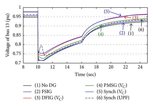
In this subsection, the behaviour of the different DGs types during a large induction motor starting is studied. An induction motor is assumed to be connected to bus 13 of the considered distributor and each of the previously mentioned DGs types is assumed to be connected to bus 15.
- (i)
The voltage control operation mode of the DFIG, PMSG wind turbine, and synchronous generator can reduce the voltage sag magnitude and duration.
- (ii)
Although the unity power factor operation mode (used with synchronous generator in this case) does not exchange reactive power with distribution system, the voltage profile is better than without DG and FSIG cases.
- (i)
The utilization of DGs, despite the type and location, reduces the voltage sag problem.
- (ii)
The DG connection point affects the voltage sag magnitude and duration.
- (iii)
The connection of the DGs downstream inductive load connection point enhances the system voltage (magnitude and sag duration) versus upstream connection except the voltage magnitude when the FSIG is utilized.
- (iv)
The voltage control operating mode presents the best performance followed by unity power factor (used with synchronous generator in this case) and finally the FSIG.
| Connection bus of DG | FSIG | DFIG | PMSG | Synch | |
|---|---|---|---|---|---|
| VC | UPF | ||||
| Minimum voltage sag (0.71 pu without DG) | |||||
| 15 | 0.713 | 0.746 | 0.729 | 0.767 | 0.746 |
| 13 | 0.713 | 0.739 | 0.724 | 0.753 | 0.734 |
| 11 | 0.714 | 0.735 | 0.723 | 0.746 | 0.729 |
| 9 | 0.715 | 0.731 | 0.722 | 0.739 | 0.725 |
| Voltage sag duration (9.66 sec without DG) | |||||
| 15 | 8.95 | 6.95 | 7.95 | 6.96 | 8.66 |
| 13 | 9.04 | 7.29 | 8.22 | 7.32 | 8.78 |
| 11 | 9.08 | 7.48 | 8.36 | 7.47 | 8.81 |
| 9 | 9.14 | 7.69 | 8.51 | 7.66 | 8.88 |
4.2. DGs Types Effect on the Distributor Voltage Interruption
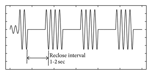
Because most faults on distribution system are transient, the power can be successfully restored within several cycles after the current interruption. Thus, most automatic circuit breakers are designed to reclose 2 or 3 times, if needed, in rapid succession. The multiple operations are designed to permit various sectionalizing schemes to operate and to give some more persistent transient faults a second chance to clear. There are special circuit breakers for utility distribution systems called “reclosers” that were designed to perform the fault interruption and reclose function particularly well.
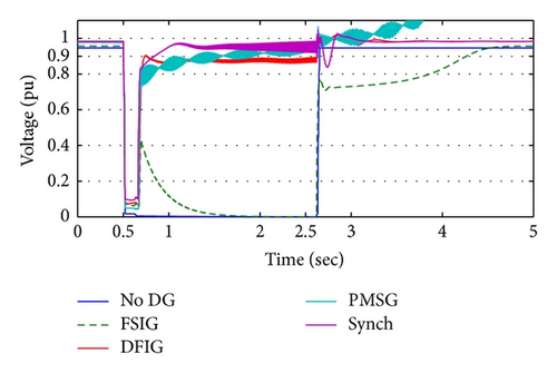
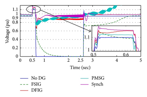
The isolated area from recloser operation is subjected to voltage interruption. The duration of voltage interruptions depends on the recloser operation characteristics. Figure 11 shows the common reclosing sequences used in many utilities which represent 1-fast, 3-delayed operation [18, 19]. In case of temporary faults, which frequently occurred in distribution system as a SLG fault, a voltage sag and swell will occur for a duration of 3 to 6 cycles followed by three-phase voltage interruption. After the elapsing of 1 to 2 sec from the voltage interruption occurrence, the reclosing process returns the isolated area to the main distribution system.
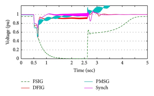
The presence of DGs in the isolated area may affect the area voltage interruption depending on the DG capability of supplying active and reactive power.
- (i)
DFIG wind turbine and conventional synchronous generator can maintain the load voltage of the isolated area within the normal limit (±5%) during the recloser opening, preventing the interruption.
- (ii)
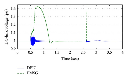
Although the PMSG can restore the isolated area voltage after fault removing to an acceptable value, it cannot keep it stable (a, b, and c) because of the incapability of DC-link voltage restoration (d).
- (iii)
In the case of the FSIG, it is noted that the isolated area is subjected to voltage interruption followed by voltage sag, which is worse than without DG case.
- (iv)
The occurrence of the SLG fault leads to a voltage swell on the unfaulted phases (c), where the DG utilization increases the voltage swell problem slightly.
5. Voltage Fluctuation and Flicker
One of the important power quality problems is the voltage flicker, which is the result of voltage fluctuations. Grid-connected wind turbines may have considerable fluctuations in the output powers, which depend on the wind turbine type. The power generated by the wind turbine fluctuates as it is much more variable than that produced by conventional generators.
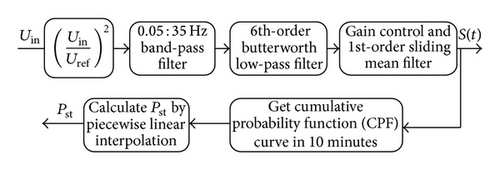
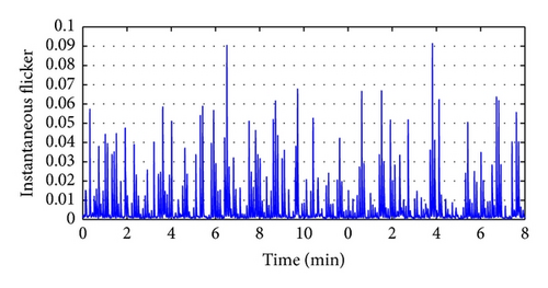
From a signal analyzing point of view, the voltage flicker is defined as a low-frequency (5 : 15 Hz) modulation of the network voltage at 60/50 Hz and the flickermeter is used to separate the carrier from the modulating wave and weigh the effects of the latter based on human sensitivity to the disturbance and generate the instantaneous sensation of the flicker S(t) and the short-term flicker Pst. The IEC flickermeter is developed in Matlab/Simulink, as shown in Figure 13, and is used to calculate S(t) and Pst [20–22]. The admissible limit of the flicker produced by the distributed generators on the MV grid is 0.35 for Pst [23].
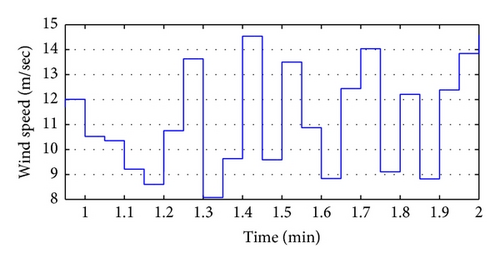
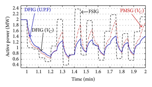
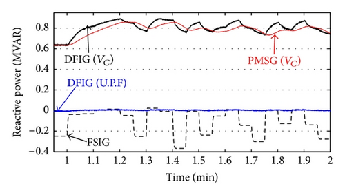
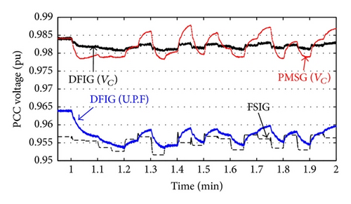
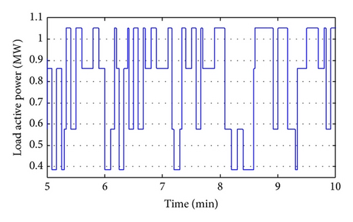
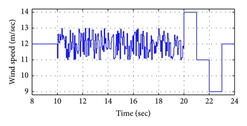
Two case studies are considered in this section. The first case studied the voltage flicker resulting from the different wind turbine types assuming wind speed variations. In the second case study, it is assumed that a constant wind speed and the voltage flicker resulted from a connected pulsating load.
- (i)
The active and reactive power change profile of the FSIG increases the distribution system flicker. The steep change of output active power and reactive power leads to a voltage fluctuation with unacceptable flicker sensation (Pst = 0.464 which is greater than the limit, that is, 0.35).
- (ii)
Despite reactive power controllability of both DFIG and PMSG with voltage control operating mode, the DFIG performance is more acceptable than the PMSG. The two paths of active and reactive power control in DFIG (RSC and NSC) are leading to smooth change in the DFIG output active and reactive power and terminal voltage as compared with the PMSG.
| FSIG | DFIG | PMSG VC |
|
|---|---|---|---|
| VC | UPF | ||
| 0.464 | 0.322 | 0.368 | 0.328 |


- (i)
The utilization of the DGs, despite the type and connection point, reduces the distribution system voltage short-term flicker.
- (ii)
The connection of the DGs, despite the type, upstream pulsating load connection point increases the system voltage short-term flicker at all the considered distribution buses.
- (iii)
The connection of the DGs downstream variable load (at bus 15), or at its terminal (at bus 13), reduces the voltage flicker at all the considered distribution buses.
- (iv)
The voltage control of the synchronous generator can reduce the voltage variation (Vmax − Vmin) so the voltage flicker is reduced compared with other DGs.
- (v)
The UPF operating mode, used with DFIG in this case, can be considered the worst case for all connection points among all considered DGs technologies.
- (vi)
Although the DFIG and PMSG operate with voltage control mode, the voltage variation (Vmax − Vmin) is larger than that in case of FSIG.
| Bus number | Without DG | FSIG | DFIG | PMSG VC | Synch VC | |
|---|---|---|---|---|---|---|
| VC | UPF | |||||
| DG connected at bus 9 | ||||||
| 9 | 0.938 | 0.687 | 0.727 | 0.753 | 0.745 | 0.487 |
| 11 | 1.289 | 0.990 | 1.017 | 1.051 | 1.041 | 0.726 |
| 13 | 1.736 | 1.385 | 1.391 | 1.433 | 1.421 | 1.045 |
| 15 | 1.735 | 1.384 | 1.390 | 1.432 | 1.420 | 1.044 |
| DG connected at bus 11 | ||||||
| 9 | 0.938 | 0.629 | 0.701 | 0.723 | 0.718 | 0.439 |
| 11 | 1.289 | 0.892 | 0.978 | 1.014 | 1.001 | 0.613 |
| 13 | 1.736 | 1.268 | 1.343 | 1.391 | 1.375 | 0.906 |
| 15 | 1.735 | 1.266 | 1.342 | 1.390 | 1.374 | 0.904 |
| DG connected at bus 13 | ||||||
| 9 | 0.938 | 0.570 | 0.670 | 0.691 | 0.685 | 0.392 |
| 11 | 1.289 | 0.808 | 0.935 | 0.968 | 0.956 | 0.547 |
| 13 | 1.736 | 1.130 | 1.286 | 1.337 | 1.313 | 0.752 |
| 15 | 1.735 | 1.129 | 1.285 | 1.336 | 1.312 | 0.751 |
| DG connected at bus 15 | ||||||
| 9 | 0.938 | 0.579 | 0.664 | 0.692 | 0.677 | 0.407 |
| 11 | 1.289 | 0.821 | 0.928 | 0.970 | 0.947 | 0.569 |
| 13 | 1.736 | 1.149 | 1.279 | 1.339 | 1.304 | 0.783 |
| 15 | 1.735 | 1.100 | 1.282 | 1.347 | 1.299 | 0.674 |
6. Harmonic Distortion
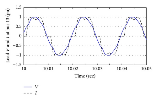
The harmonic current distortion in the distribution system is generated by the nonlinear loads interacting with power system impedance and gives rise to the harmonic problems. The effect of harmonics in the power system can lead to degradation of power quality at the consumer’s terminal, increase of power losses, and malfunction in communication system. The degree of variation is assessed at the PCC, where consumer and supplier areas of responsibility meet. Wind turbines DGs can also contribute to the harmonic distortion of the voltage waveform. In the first edition of IEC 61400-21, only wind turbines with power converters should be tested for harmonics. However, this will probably be changed in the second edition, requiring measurements of harmonic currents for all types of wind turbines [24–26].
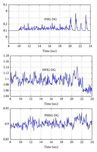
- (i)
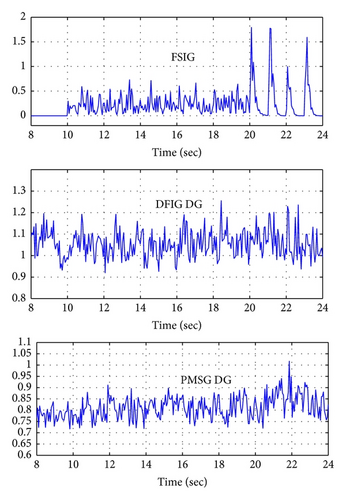
For constant or variable wind speed, the values of the injected current TDD and the terminal voltage THD are within the admissible range.
- (ii)
Only the FSIG is affected with wind speed variation, where the TDD and THD nearly equal zero for constant wind speed region (t < 10 sec).
| Total Demand Distortion (TDD) of the DG injected current | Total Harmonic Distortion (THD) at the DG PCC |
|---|---|
| 5.0% | 5.0% |
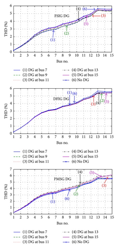
- (i)
Despite the DG type, the THD nearly does not change after wind turbine DG connection.
- (ii)
The connection point of the wind turbine DG has no effect on the voltage THD.
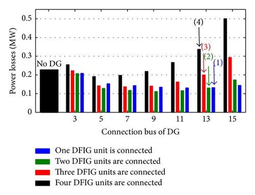
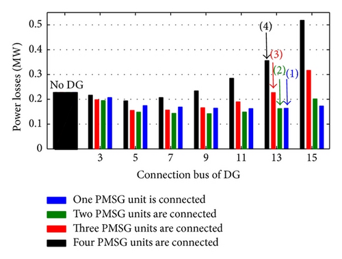
7. DGs Penetration Ratio and Connection Point Effect on the Distributor Losses
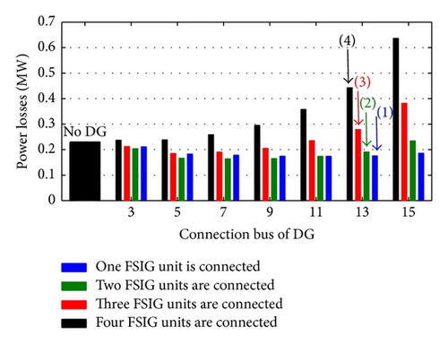
Although the active power losses in the distribution system are not a technical power quality factor that can limit the amount of the penetrated DGs, they are considered as an important economical factor [17]. Therefore, in this section, the active power losses of the distribution system, shown in Figure 1, are determined for different scenarios of the connected DGs and their connection points.
- (i)
For Maximum Loading Condition. The adoption of voltage control operation mode (with DFIG, PMSG, and Synch generator) leads to the largest reduction of power losses because these generators can supply the active and reactive loads locally, decreasing the magnitude of the distribution feeders current. On the other hand, the usage of FSIG does not cause a great reduction in the active power losses. In this case, the generator consumes reactive power from the network, raising the magnitude of the currents circulating in the feeders. The losses behaviour in the presence of unity power factor (with synchronous generators in this case) is situated between the other two cases because these generators supply locally active power but do not provide or consume reactive power.
- (ii)
For Minimum Loading Condition. The presence of the DGs increases the active power losses, independent of the generator employed. In this situation, a large amount of active power generated is exported to the substation, adversely influencing the distribution system losses. The usage of the voltage control operating mode can be related to the worst case under losses viewpoint because the generator consumes a large amount of reactive power to keep the terminal voltage at 1 pu.
| Number of turbines | FSIG | DFIG | PMSG | Synch | |
|---|---|---|---|---|---|
| VC | UPF | ||||
| Maximum demand (losses without DG equal 0.2277) | |||||
| 1 | 0.1855 | 0.1445 | 0.1491 | 0.1501 | 0.1728 |
| 2 | 0.2342 | 0.1737 | 0.1787 | 0.1803 | 0.2016 |
| 3 | 0.3817 | 0.2939 | 0.3015 | 0.3037 | 0.3166 |
| 4 | 0.6367 | 0.5007 | 0.5129 | 0.5159 | 0.5183 |
| Minimum demand (losses without DG equal 0.0027) | |||||
| 1 | 0.0428 | 0.0642 | 0.0579 | 0.0686 | 0.0402 |
| 2 | 0.1597 | 0.2060 | 0.2116 | 0.2169 | 0.1497 |
| 3 | 0.3530 | 0.4263 | 0.4380 | 0.4458 | 0.3285 |
| 4 | 0.6267 | 0.7237 | 0.7424 | 0.7616 | 0.6167 |
- (i)
The minimization of power losses depends, explicitly, on the connection point of the DG and its penetration ratios.
- (ii)
For small penetration ratios, the suggested connection point of any one of the considered wind turbine DGs is near the far end of the distribution system. With penetration ratio increase, the suitable DG connection point comes near the substation side.
- (iii)
The use of voltage control mode with DFIG or PMSG reduces the power losses despite the connection point or the DG penetration ratio.
8. Conclusions
- (1)
The utilization of the DGs may be one of the power quality enhancement methods according to some factors such as the DG type, operating mode, penetration value, and connection point.
- (2)
The wind turbine DGs-based DFIG and PMSG with voltage control mode have nearly the same performance of conventional synchronous generator during steady state and transient operating conditions.
- (3)
The penetration ratio of wind turbine DGs operating with voltage control mode can reach 100% maximum distribution system loading without violating the admissible voltage in the steady states or losing system stability during transient conditions.
- (4)
The power quality of the distribution system is very sensitive to the connection point of the embedded DGs, where the following are considered:
- (i)
The distribution system load voltage improvement, in the steady state, requires a connection of the DG near the far end of the distributor despite its penetration.
- (ii)
Active power losses minimization depends, significantly, on the DG connection point and its penetration ratio. The connection point should be near the distribution far end for minimum penetration ratios and must be transposed forward the main substation with penetration ratio increase.
- (iii)
The voltage sag problem can be reduced by connecting the DG downstream source of voltage sag problem.
- (iv)
The voltage interruption problem can be solved by suitable connection of the DG with respect to protection systems. The DFIG wind turbine with voltage control mode can prevent the voltage interruption in the distribution isolated area similar to synchronous generators.
- (v)
The connection of the DG, despite its type, downstream voltage flicker sources reduces the voltage flicker problem at all distribution system buses.
- (vi)
The THD produced from the nonlinear loads is not affected by the DG, despite its type and connection point.
- (i)
- (5)
The voltage flicker due to wind turbine variable output power is still within acceptable limits until with pulsating wind speed variation.
- (6)
The main problem of the FSIG wind turbine DG appears manifestly during transient conditions due to the lack of reactive power support.
- (7)
The DC-link of the DFIG and PMSG represents the main challenge of these wind turbine operations during transient conditions.
- (8)
The disconnection of the wind turbine DGs during system faults listed in interconnecting distributed resources with electric power systems standard must be restudied as well as the ability of coordination between the protection devices and the wind turbine control system.
Competing Interests
The authors declare that they have no competing interests.
Appendix
-
(A) Line data in ohm:
-
Z1-2: 0.1114 + j0.3340
-
Z2-3: 0.1310 + j0.3930
-
Z3-4: 0.1572 + j0.4716
-
Z4-5: 0.1048 + j0.3144
-
Z5-6: 0.0590 + j0.1769
-
Z6-7: 0.0236 + j0.0707
-
Z7-8: 0.0707 + j0.2122
-
Z8-9: 0.0354 + j0.1061
-
Z9-10: 0.0482 + j0.1446
-
Z10-11: 0.0844 + j0.2530
-
Z11-12: 0.0482 + j0.1446
-
Z12-13: 0.0985 + j0.2954
-
Z13-14: 0.1231 + j0.3693
-
Z14-15: 0.1539 + j0.4616.
-
-
(B) Load data in KVA:
-
Load 2: 133.3 + j100
-
Load 3: 1466.7 + j1100
-
Load 4: 266.7 + j200
-
Load 5: 1600 + j1200
-
Load 6: 266.7 + j200
-
Load 7: 400 + j300
-
Load 8: 266.7 + j200
-
Load 9: 533.3 + j400
-
Load 10: 266.7 + j200
-
Load 11: 400 + j300
-
Load 12: 266.7 + j200
-
Load 13: 400 + j300
-
Load 14: 266.7 + j200
-
Load 15: 133.3 + j100.
-
-
(C) Transformer (T1) data:
-
8 MVA 66/11 kV Δ/Yg
-
R1 = R2 = 0.002 pu
-
X1 = X2 = 0.02 pu
-
Rm = Xm = 500 pu.
-
-
(D) Transformer (T2) data:
-
2.2 MVA 11/0.575 kV Δ/Yg
-
R1 = R2 = 0.002 pu
-
X1 = X2 = 0.02 pu
-
Rm = Xm = 500 pu.
-
-
(E) FSIG wind turbine (2 MVA) data:
-
Rs = 0.016 pu
-
Lls = 0.060 pu
-
pu
-
pu
-
Lm = 3.50 pu
-
Hg = 0.700 s
-
HT = 4.000 s.
-
-
(F) DFIG wind turbine (2 MVA) data:
-
Rs = 0.023 pu
-
Lls = 0.180 pu
-
pu
-
pu
-
Lm = 2.90 pu
-
Hg = 0.685 s
-
HT = 4.32 s
-
CDC-link = 10000 μf
-
Vdc-nominal = 1150.
-
-
(G) PMSG wind turbine (2 MVA) data:
-
Rs = 0.006 pu
-
Lls = 0.180 pu
-
Hg = 0.62 s
-
HT = 4.32 s
-
CDC-link = 90000 μf
-
Vdc-nominal = 1100.
-
-
(H) Synchronous generator (2 MVA) data:
-
Xd = 1.400 pu
-
Xq = 1.372 pu
-
pu
-
pu
-
pu
-
pu
-
Xl = 0.050 pu
-
Ra = 0.00014 pu
-
s
-
s
-
s
-
s
-
H = 1.5 s.
-


