Analysis of Filter and Waveguide Effect Based on the MIM Nanodisk with a Metallic Block
Abstract
A novel and meaningful plasmonic filter based on the metal-insulator-metal (MIM) waveguides directly connected to a nanocavity with a metallic block is proposed and demonstrated numerically. By the effective index method and the resonant theory of disk-shaped nanocavity, we reveal that the resonant wavelengths can be simply tuned by adjusting the height of the block, which is in accordance with the results calculated by finite-difference time-domain (FDTD) simulations. We also rotate the metallic block to achieve two resonant modes. One mode shows a blue shift, and the other mode shows a red shift. It is shown that the proposed structure performs as a bend waveguide not a filter when the width of the block increases to hundreds of nanometers. The proposed structure will have significant potential applications in nanointegrated circuits for optical filtering and processing.
1. Introduction
Surface plasmon polaritons (SPPs) are deriving from coupling of electromagnetic waves with oscillations of free electrons in a metal and supported at the insulator/metal interface [1]. Since SPPs can be confined in a subwavelength-scale area beyond the diffraction limit, they are regarded as information carriers for highly integrated photonic circuits, such as particles [2, 3], grooves [4–6], cavities [7–11], and apertures [12, 13]. In addition to the merit of miniaturization for these devices, their unique characteristics can satisfy various applications. Take the basic waveguide, for instance, directional couplers and splitters, and even modulators utilizing electro/thermoeffect [14, 15]. Typical plasmonic waveguides are the insulator-metal-insulator (IMI) waveguides and the metal-insulator-metal (MIM) waveguides [5, 16–21]. It is well known that the IMI waveguide exhibits less propagation loss, leading to longer propagation length than the MIM waveguide [16]. On the other hand, from a point of confining light, since the skin depth of SPPs fields into the dielectric medium is much longer than that into the metallic medium at the interfaces [19], the MIM waveguide is better than the IMI waveguide. Thus, the MIM waveguide is more suitable for high optical integration.
Specifically, a fine filter-like behavior was achieved in a Bragg reflector alternatively stacking MIM waveguides with two kinds of dielectrics [22]. For the sake of simplifying the fabrication of Bragg reflectors and decreasing the propagation length for SPPs, some simple plasmonic filters have been proposed. For example, the proposed structure based on MIM waveguides with a nanodisk resonator acts as a band-pass filter [23]. It has also been reported that the one-end-sealed MIM waveguide reveals fine filtering effect [24]. Subsequently, unidirectional excitation of SPPs in T-shaped waveguide with nanodisk resonator has been analyzed theoretically and numerically [25]. More recently, comb-like filters have been demonstrated [26]. These previous structures merely perform as filters. Thus, the investigation and design of a structure based on the MIM waveguides functioning not only as a filter but also as a bend waveguide are highly desired for various applications.
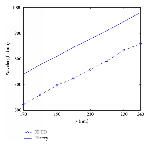
In this paper, we propose a novel structure based on the MIM waveguides directly connected to a nanodisk resonator with a metal-block core. In order to make our proposed structure be easily seized, we discuss the structure without the metal-block core at the beginning. The difference between simulation and theoretical results is related to the nanocavity not being sealed. Then we put the metallic block into the nanocavity. With the effective index method (EIM) and the resonant mode theory (RMT), we examine wavelength shifts of the resonant modes, which are also validated by finite-difference time-domain (FDTD) [27] method. Another result obtained by FDTD simulations reveals that regular shifts of resonant wavelengths can be manipulated by the block’s rotation degree. Finally, when the width of the block changes from tens of nanometers to hundreds of nanometers, the proposed structure performs as a bend waveguide, not a filter.
2. Model Creation and Theories
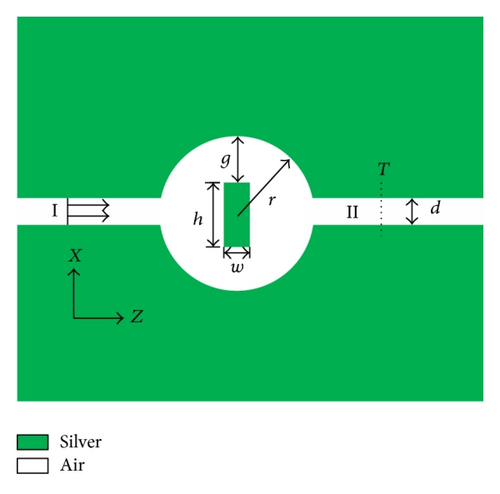
In this paper, we employ our 2D-FDTD program code to simulate the interaction between metal and incident waves. In our calculation, the current density is induced into Maxwell’s equations since the real part of the permittivity of metal is negative. The grids are terminated by ten-cell-thick convolutional perfectly matched layer (i.e., CPML). The spatial mesh cells are set to Δx = Δz = Δs = 5 nm, and the time step and the total number of time steps are taken as Δt = Δs/2c = 8.33 × 10⁻¹⁸ s and 2 × 10⁴, respectively. The small size of cells and large total number of time steps ensure that the values of electromagnetic field and current density in spatial grids are convergent and stable. The fundamental TM mode of the MIM waveguide is excited by a plane wave source whose wavelength ranges from 600 nm to 1550 nm. One frequency-domain field and power monitor is set to detect the transmission power P.
3. Simulation Results and Discussion
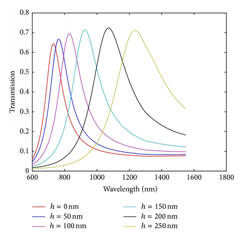
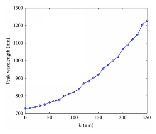
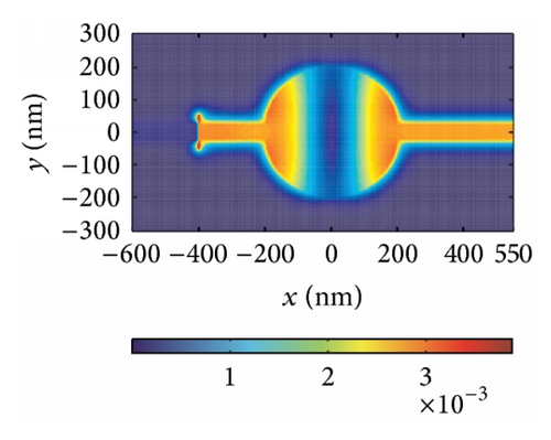
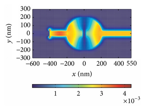
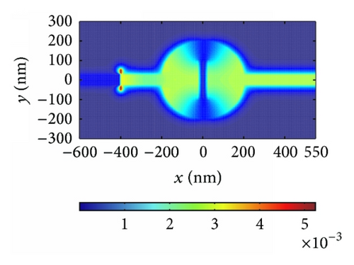
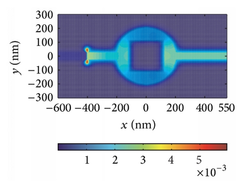
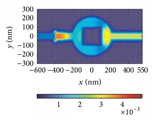
Next, we put a metallic block into the nanodisk. We investigate the influence of the height of the block on the resonant wavelengths firstly by using the FDTD method and then by using the RMT. The height of the block h is variable and the width w is set as 50 nm, while other parameters are fixed as above. Figure 4(a) shows the transmission spectra with the different heights of the block. From Figure 4(b) we can find that the resonant wavelengths tend to exhibit a red shift with the increase of the block’s height, which is in accordance with (2)–(4). Magnetic-field |Hz| distributions at λ = 728 nm with h = 0, λ = 823 nm with h = 100 nm, and λ = 1066 nm with h = 200 nm are depicted in Figures 4(c)–4(e). We observe that the excitations of resonant modes emerge in the nanocavity under the three cases where the incident light can pass the MIM plasmonic structure. According to above simulations and analysis, it is obvious that we can achieve a fine filter-like behavior by tuning the height of the metallic block.
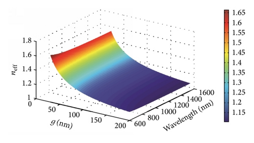
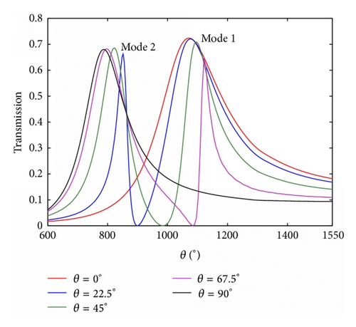
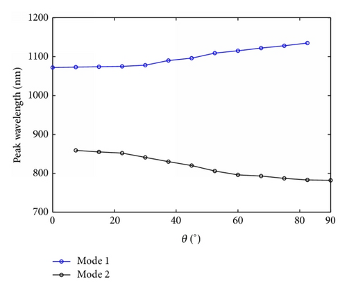
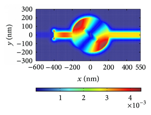
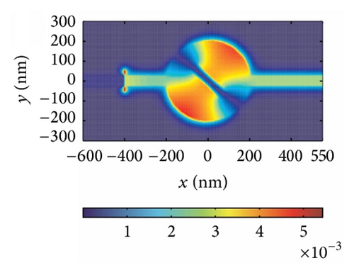
Another parameter θ, which stands for the block’s rotation degree, plays an important role in modulating the resonant wavelength. The rotation of the block leads to a displacement of the dielectric core, which makes the direction of magnetic oscillation variable. In addition, the change of the direction of magnetic oscillation makes g different, affecting neff directly as shown in Figure 2. Hence, it is clear that the effective index changes when the symmetry of the structure is destroyed by modulating the block’s rotation degree θ. The effective index neff is an important factor influencing resonant wavelength λm as shown in (4). Thus, we can manipulate the resonant wavelengths by changing the value of the block’s rotation degree θ, which is verified by FDTD simulations. The structural parameters are set as w = 50 nm and h = 200 nm. Then we start to rotate the block counterclockwise. Figure 5(a) shows the transmission response corresponding to θ = 0°, 22.5°, 45°, 67.5°, and 90°. There is only one transmission peak at λ = 1066 nm when θ is zero. When the rotation degree is 90° > θ > 0°, two transmission peaks appear around λ = 820 nm and λ = 1096 nm, which are called mode 2 and mode 1, respectively. With increase of rotation degree θ, mode 1 exhibits a slight red shift, while mode 2 presents a blue shift (as shown in Figure 5(b)), leading to the wavelength gap between two modes getting larger. When θ is the value of 90°, only one transmission peak is observed at λ = 782 nm. Furthermore, Figures 5(c)–5(e) depict the field distributions of |Hz| of transmission peaks at λ1 = 820 nm and λ2 = 1096 nm, and transmission valley at λ3 = 980 nm when θ is the value of 45°, which match Figure 5(a) perfectly. Therefore, one can choose special rotation degree to design the filter with demanded channel.
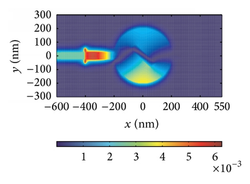
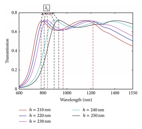
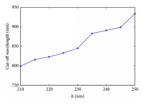
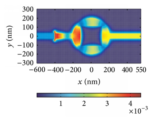
Finally, we find that the proposed structure changes from a filter to a waveguide under the special parameters. When we set the width of the block to be 250 nm and change the height from 210 nm to 250 nm, the structure performs as a bend waveguide, not as a filter. In Figure 6(a), we show the calculated transmission as a function of wavelength. We can see that the loss is about 10% at longer wavelength. The critical wavelength λC regarded as the original wavelength of the waveguide under which the transmission coefficient is max is 790 nm (823 nm, 845 nm, 903 nm, and 934 nm) for h = 210 nm (220 nm, 230 nm, 240 nm, and 250 nm). Hence, it is clear that the wavelength λC increases monotonously with h increasing as shown in Figure 6(b). That is, the operating wavelength range widens as h decreases. The reason why our structure changes from a filter to a waveguide is that the nanocavity is connected to two MIM waveguides directly, leading to lots of pathways along which SPPs travel. Therefore, the resonant wavelengths differ slightly, which contributes to the change from a filter to a waveguide. For the sake of confirming our analysis, field distributions |Hz| under some resonances are shown in Figures 6(c)–6(e) as examples.
4. Conclusion
In this paper, the novel filter effect can be realized based on the MIM plasmonic nanodisk with a metal-block core. The structure without a block inside the cavity is studied to be compared with the proposed structure. The difference between simulation and theoretical results is related to the cavity not being sealed, while (5) is fit for ideal disk. The proposed structure reveals perfect filter effect by easily modulating the height of the block. The resonant wavelengths tend to exhibit a red shift with the increase of the height of the block. The result achieved by FDTD simulations can be accurately analyzed through the EIM and the RMT. We also find the proposed structure produces two modes (i.e., Mode 1 and Mode 2) through tuning the block’s rotation degree by means of rotating the strip counterclockwise. Mode 1 and mode 2 tend to exhibit a red shift and a blue shift, respectively. Furthermore, when the width of the block is assumed as 250 nm and the height of the block changes from 210 nm to 250 nm, the proposed structure performs as a bend waveguide, not a filter. The FDTD results are verified by the theoretical analysis. Undoubtedly, the ways to give rise to filter effect are ingenious and wonderful. We believe that our fundamental study could find promising applications in the highly integrated plasmonic devices for optical processing and filtering.
Conflict of Interests
The authors would like to declare that they do not have any commercial or associative interests that represent a conflict of interests in connection with the submitted paper.
Acknowledgments
This work was supported by the National Natural Science Foundation of China (Grant nos. 11074069 and 61176116) and the Specialized Research Fund for the Doctoral Program of Higher Education of China (Grant no. 20120161130003).


