Static Kirchhoff Rods under the Action of External Forces: Integration via Runge-Kutta Method
Abstract
This paper shows how to apply a simple Runge-Kutta algorithm to get solutions of Kirchhoff equations for static filaments subjected to arbitrary external and static forces. This is done by suitably integrating at once Kirchhoff and filament reference system equations under appropriate initial boundary conditions. To show the application of the method, we display several numerical solutions for filaments including cases showing the effect of gravity.
1. Introduction
Filamentary bodies such as rods, ribbons, and wires are present in many scales from microscopic to astrophysical bodies. Marine cables [1], hair beams [2], rubber bands, microfibers [3], nanowires [4], and DNA molecules [5] share common dynamics, which is testified by the onset of rich elastic phenomena such as buckling, coiling, and looping [6]. The writhing instability for example [7, 8] is a looping process in which the spatial configuration of an elastic filament changes remarkably as a response to an applied external torque, the change itself as a minimization process of the filament elastic energy.
The dynamics of filamentary bodies has been the subject of extensive research in continuum mechanics with the aim of establishing either exact or approximate solutions for thin filaments. The theory itself started with Kirchhoff [9, 10] in 1892 and Clebsch and Love [11] who considered small deformation of thin rods within the elastic range. The theory was developed under special assumptions that later became the approximations adopted by the so-called simple bending and torsion theory [12]. Although the deformations of infinitesimal portions of a rod in the theory may be small, the overall deformation is quite large and allows the coiling and looping phenomena above mentioned.
Exact solutions of Kirchhoff equations for static rods are well known. Shi and Hearst found the most general analytical solution to the static Kirchhoff rod, which they called helix on a linear helix [13]. Nizzete and Goriely [14] used the equivalence between the static Kirchhoff equations for rods with circular cross-sections and the Euler equations for spinning tops to provide a classification of all different equilibrium solutions for a filament. Chouaieb et al. [15] completed the study of existence and stability of helical structures within the Kirchhoff rod model. Goriely and Tabor [7, 16] developed a dynamical method to study the stability of equilibrium solutions of the Kirchhoff rod model, based on a time-dependent perturbation scheme, thus providing a framework for classification of new solutions. This method has been used, for example, to study DNA rings [17, 18] and nanowires [19] under large stresses.
In biology and nanoscience, for example, most of the interesting filaments are the ones subject to diverse boundary conditions. Tobias et al. [20] derived analytic expressions for the equilibrium configurations of filaments representing long segments of a DNA double helix under different end conditions. da Fonseca et al. [19, 21] recently used the Kirchhoff model to propose schemes for the study of the elastic properties of nanowires and nanosprings. McMillen and Goriely [22] obtained equilibrium solutions for the tendril perversion structure within the framework of the Kirchhoff rod model, which are heteroclinic orbits joining asymptotically two helices with opposite torsion. Gottlieb and Perkins [23] investigated spatially complex forms in a BVP governing the equilibrium of slender cables subjected to thrust, torsion and gravity. In a very comprehensive work, Powers [24] treats the dynamics of filaments in viscous fluids and solves some interesting cases.
Despite the success of the above examples of equilibrium solutions of Kirchhoff model subject to some particular types of boundary conditions, boundary value problems are still a great challenge in the study of the static and dynamics of filaments. The main approach to find out equilibrium solutions for filaments subject to arbitrary boundary conditions is to rely on numerical computation. Examples are the use of finite element methods to obtain the equilibrium solutions of supercoiled DNAs [25], numerical package tools to solve differential equations based on a Hamiltonian formalism of the rod model [26], and a method of linearization of Kirchhoff equations, to find equilibrium solutions of open rods with fixed ends [27].
In this paper, we explore the use of straightforward methods, as the use of implicit or explicit iterative methods such as Runge-Kutta of a given order subjected to boundary conditions, to solve static filaments under the action of (static) external forces. This is done by a numerical procedure in which the Kirchhoff equations and the reference frame of the filament centerline are combined to solve the boundary value problem. The organization of the paper is as follows: we first make an introduction to the general Kirchhoff equations of rods (Section 2) and show how to use the external force to obtain a transformation matrix that couples the system of Kirchhoff equations to the filament reference frame (Sections 2.1 and 2.2). In Section 2.2 we introduce the general formulation of boundary value problems. In Section 3 we present numerical examples of closed and open rods subjected to boundary conditions, including illustrations of the effect of gravity in several kinds of filamentary solutions obtained in the absence of external forces. Section 4 is in fact a note on how to transform the filament problem into several types of boundary value problems. Finally, Section 5 (conclusion) summarizes our main results.
2. Kirchhoff Model for Thin Rods
In order to write the static equation for rods, we first make a short summary of the main dynamical equations of rods (Figure 1) that are valid under the following definitions and assumptions [10]: (i) a rod or filament is a 3D body in which two of the dimensions are much smaller than a third one which defines the axis or centerline of the rod; (ii) a rod is viewed as a sequence of short segments of area A which are held together by contact forces, p, between adjacent segments sharing the same elastic properties; (iii) the cross-section of a segment remains undistorted and perpendicular to the axis defined by the third dimension. The axis may be taken as the centroid of the section; (iv) displacements are always small and the breakdown of the elastic limit is never achieved. In this way, stresses and torques are always proportional to strains in full accordance with Hook′s law.
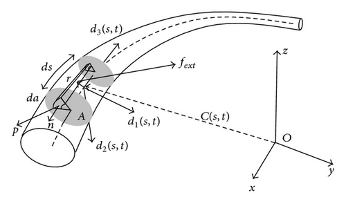
With this in mind, we considered a segment of a rod or thin filament with length ds as shown in Figure 1. A given segment can be assessed by the arclength parameter s which runs from 0 to L, the total rod length. The rod has cross-section A which is symmetrical in relation to the centroid position defined by the vector C(s, t) written in relation to a fixed frame with origin O in the laboratory.
the last relations are twist and spin equations of the rod. Writing k in the d-basis, k1 and k2 are the curvature vectors and k3 is the twist density. Vector w is the spin vector and represents the angular momentum of the section in the local basis.
and the curve can be followed by the time dependence of the d3 vector.
with E and G being Young′s and the shear moduli of the material, respectively, and J the axial moment of inertia. Equation (12) was written in such a way that if k1 = 0 and k2 = 0, the filament is naturally straight.
Note that the static condition does not imply that the force will be constant throughout the filament since there is an interaction among different components, arising from terms of the rotated coordinate system that is attached to each filament segment.
2.1. Integrals for the External Reference System
After integration of (10) and (11), Equations (20) and (21) must be integrated in order to obtain a description of the rod in the fixed system.
and the s-“dynamics” given by (20) in accordance to the K matrix.
2.2. Coupling the Kirchhoff Equations to the Reference Frame System
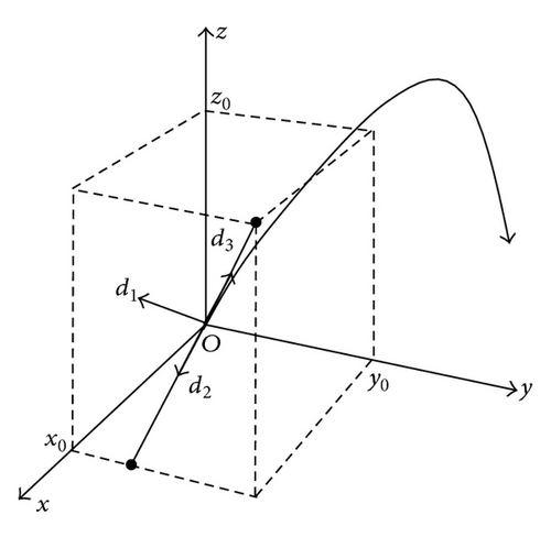
The total number of degrees of freedom in the specification of a solution is therefore 12.
3. Solving the Initial Value Problem with and without External Force
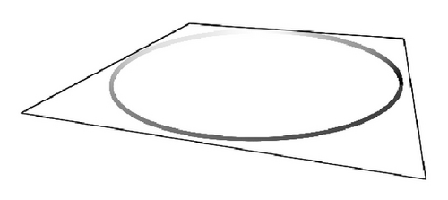
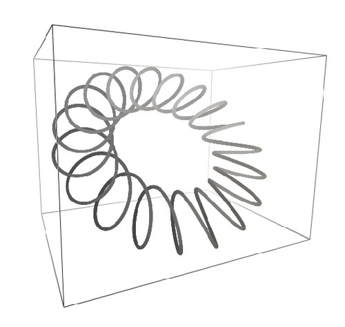
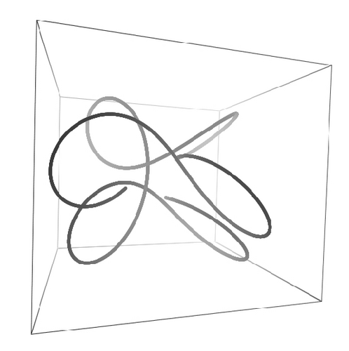
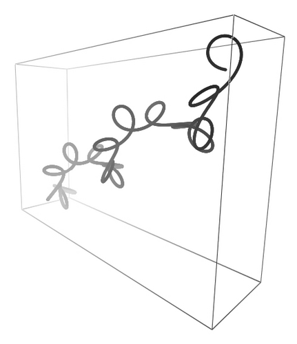
and the coil filament starts from the origin. Space periodic solutions, C(0) = C(L), can also be generated. Figure 4 contains filaments with 3000 steps with circular cross-section, I1 = I2 and the same initial orientation. The parameters used to generate each curve are as follows: (a) E = 0.2, G = 0.5, k1(0) = 0.0, k2(0) = 0.1, k3(0) = 0.1, F1(0) = 0.0, F2(0) = 0.01, F3(0) = 0.0, I1 = 1.0, L = 63.0, (b) E = 1.0, G = 2.5, k1(0) = 0.0, k2(0) = 1.3, k3(0) = 0.01, F1(0) = 0.0, F2(0) = 0.9885, F3(0) = 1.0, I1 = 2.0, L = 71.0, (c) E = 0.1, G = 2.5, k1(0) = 0.0, k2(0) = 1.3, k3(0) = 0.01, F1(0) = 0.0, F2(0) = 0.9885, F3(0) = 1.0, I1 = 2.0, L = 13.0, and (d) E = 0.2, G = 2.5, k1(0) = 0.0, k2(0) = 1.3, k3(0) = 0.01, F1(0) = 0.0, F2(0) = 0.99, F3(0) = 2.0, I1 = 2.0, L = 35.0. (a) and (b) are almost closed solutions. In order to produce them, specially tuned boundary conditions were chosen as described in [28]. In this sense, the method is unable to produce closed solutions without further tuning of boundary values and other parameters. By changing the value of Young′s modulus, the curve opens itself and becomes a complex helix as shown in Figure 4(d).
Since in the last examples, I1 = I2, then k3(s) = k3(0) for all s according to the last element of (38). Young′s modulus E multiplies I1 and I2 as shown by (15), so that the cases for which I1 ≠ I2 either represent homogeneous filaments with noncircular cross-sections or circular cross-section filaments with anisotropic bending stiffness. To illustrate this case, we show in Figure 4 a helix with I1 = 3.0 and I1 = 2.0 and decreasing values of G, the shear modulus, as indicated in the figure. For this case we have E = 1.0, k1(0) = 0.0, k2(0) = 1.0, k3(0) = 0.07, F1(0) = 0.0, F2(0) = 0.21, F3(0) = 0.0147, L = 63.0 and 3000 points. As the shear modulus decreases, the filament stretches as a response to less torsion rigidity.
Equation (52) shows the appearance of crossed terms in the integration scheme of (38). For other external forces pointing to arbitrary directions, or under the action of external torques, the same procedure should be applied by writing whatever fixed components in terms of the d-basis through (50).
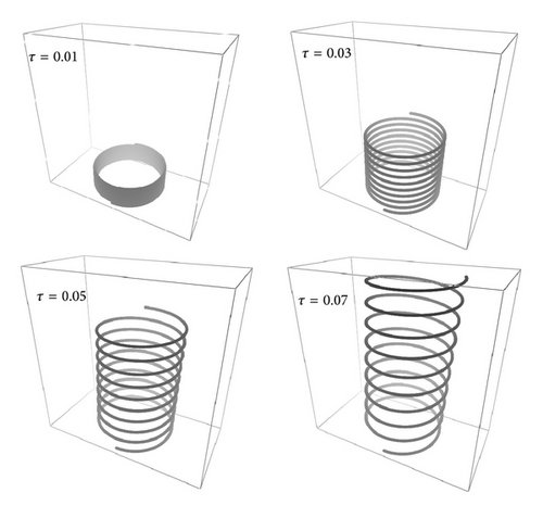
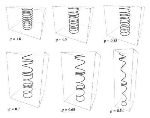
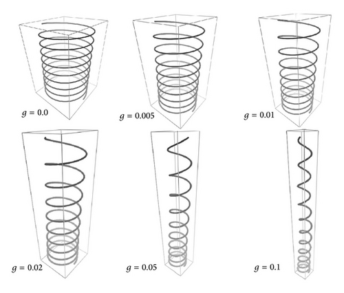
In order to illustrate gravity effects, we consider two Frenet helices with distinct orientations. In the first case (Figure 5), the gravity zero helix is vertical. The parameters of Figure 5 are as follows: E = 1.0, G = 0.5, k1(0) = 0.0, k2(0) = 2.0, k3(0) = 0.1, F1(0) = 0.0, F2(0) = 0.0, F3(0) = 0.0, I1 = 1.0, I2 = 1.0, L = 30.0, r = 1.0, A = 1.0 and g is varied as indicated in the figure. These simulations were obtained with 3000 steps. We note that, as g is increased, the helix distorts itself resembling a “curly-hair” filament. The helix pitch at the lower turns is smaller than the upper ones, because these must support most of the filament weight and are therefore more stretched.
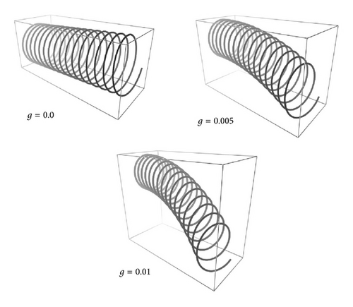
Another possible solution comes from horizontal helices under the action of gravity. In Figure 7, a sequence of Frenet helix is shown with the same initial conditions of Figure 6 but with L = 50.0. The orientation of d(0) is now orthogonal to the previous case so that gravity is orthogonal to the helix main axis. The natural spring is deformed toward −z as intuitively expected by simple experiments with coils and ribbons.
4. Note about Static Filament Solutions as a Boundary Value Problem
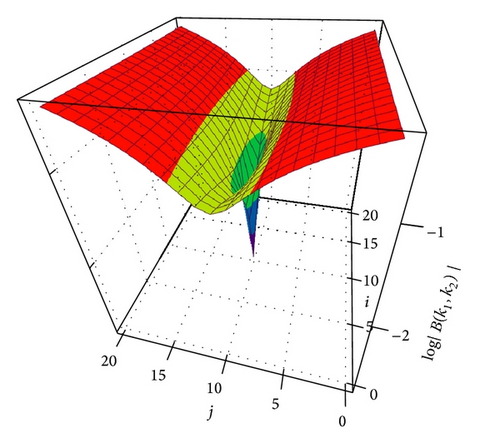
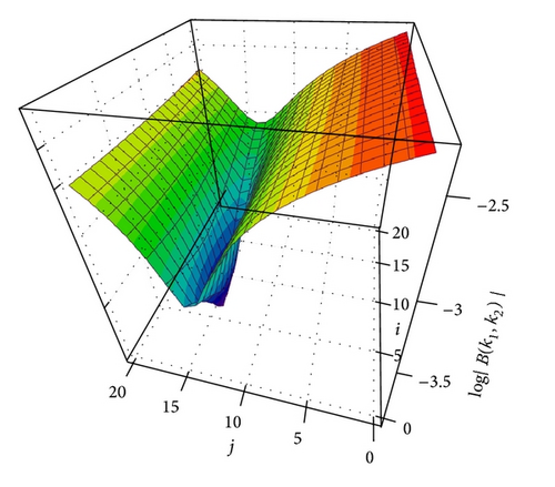
which is essentially similar to (61) with an extended Jacobian.
5. Conclusions
In this paper we have obtained static solutions for Kirchhoff′s equations by numerical integration, using a scheme in which both Kirchhoff and reference system equations are integrated at once. By incorporating additional dimensions, the final vector that describes the filament curve is also obtained. The scheme allows a quick and easy determination of solutions under the action of external (static) forces. These appear as interaction terms in both force and moment equations, (10), provided the components of force and torque are expressed in the local reference system. This was the case of gravity and is also the case of many other external forces such as the centrifugal acceleration for a filament in a rotating system, the electric force for a charged filament [30], or a magnetized filament in the presence of magnetic fields [31].
In order to obtain solutions, we have treated the integration of the static equations as initial and boundary value problems. As an initial value problem, the filaments can be generated as solutions of a set of first order differential equations subjected to 18 initial values. Some of these values are linked to each other (due to the parametric dependency of the S matrix), so that the actual number of degrees of freedom for the initial values is 12. This sets the maximum number of dimensions in the constraints for the boundary value version of the filament problem. As a boundary value problem, several types of initial and final constraints can be written.
In deriving Kirchhoff′s equations for static filaments, we have kept the filament density constant. The effect of nonhomogeneities in rods can be easily incorporated into Runge-Kutta system as an additional term in both force and moment laws. The same is valid for wires with nonuniform elastic constants such as E and G. In summary, several classes of static solutions can be stud by using the approach here presented.
Conflict of Interests
The author declares that there is no conflict of interests regarding the publication of this paper.
Acknowledgments
The author would like to thank Christine Fernandes for the preparation of the LaTeX version of this paper, Marcus A. M. de Aguiar and Alexandre F. da Fonseca (IFGW/UNICAMP) for useful discussions.


