Shifting Control Algorithm for a Single-Axle Parallel Plug-In Hybrid Electric Bus Equipped with EMT
Abstract
Combining the characteristics of motor with fast response speed, an electric-drive automated mechanical transmission (EMT) is proposed as a novel type of transmission in this paper. Replacing the friction synchronization shifting of automated manual transmission (AMT) in HEVs, the EMT can achieve active synchronization of speed shifting. The dynamic model of a single-axle parallel PHEV equipped with the EMT is built up, and the dynamic properties of the gearshift process are also described. In addition, the control algorithm is developed to improve the shifting quality of the PHEV equipped with the EMT in all its evaluation indexes. The key techniques of changing the driving force gradient in preshifting and shifting compensation phases as well as of predicting the meshing speed in the gear meshing phase are also proposed. Results of simulation, bench test, and real road test demonstrate that the proposed control algorithm can reduce the gearshift jerk and the power interruption time noticeably.
1. Introduction
In the past few years, hybrid electric vehicles (HEVs) have demonstrated advantages in reducing the fuel consumption and pollution emissions [1–3]. Compared with conventional HEVs, plug-in hybrid electric vehicles (PHEVs) can recharge from an external source. Before the technology of pure electric vehicles (EV) becomes mature, PHEVs offer a feasible solution to the transportation in which part of the required petroleum resource is replaced with electricity [4].
The driveline system plays a crucial role in vehicle’s fuel-saving performance and driving comfort. Automated manual transmission (AMT) has been a decent candidate for the power transmission of heavy HEVs for its high efficiency, low cost, and high reliability. Besides, AMT can be modified in the conventional transmissions. However, AMT has still some drawbacks of power interruption and shifting jerk in the gear shifting process. Furthermore, the excessive wears of the clutch disc and synchronizer affect the application of AMT in HEVs [5–7]. Much research has been conducted to find better solutions to AMTs’ shortcomings in HEVs. For reducing the power interruption time, Baraszu and Cikanek [8] proposed that the vehicles should be directly driven by motor during the gear shifting process in parallel HEVs equipped with AMT. Jo et al. [9] and Liao et al. [10] introduced a control strategy which controlled the torques and speeds of the engine and motor to reduce the synchronizing torque of AMTs’ synchronizer and clutch. So far few literatures on the gear shifting control strategies without disengaging the clutch for HEVs equipped with AMT have been reported [5, 11, 12]. But those disadvantages of AMT could not be thoroughly avoided due to the slow response of engine.
In order to solve these problems, we designed a new automatic transmission, namely, electric-drive automated mechanical transmission (EMT), which improved the structure of AMT. By removing the synchronizer of AMT and adding the drive motor and the control system to it, the EMT was constructed. With the rapid response of the motor, it could control the speed and torque of the motor to achieve shifting synchronization in gear shifting process. Thus the acceleration steadiness and the degree of smoothness of the vehicle are achieved [13–17], and consequently the vehicle drivability is improved.
In this paper, a gear shifting control algorithm is designed for a single-axle parallel PHEV equipped with EMT. To do this, the dynamic properties of the gearshift process are discussed, and then the dynamic model of the powertrain system is built up. The EMT is integrated to a plug-in hybrid electric bus (PHEB). To study the effectiveness of the proposed gearshift control algorithm, the bench test and real road test are performed. The results of the simulation and tests prove that the presented control algorithm can obtain an outstanding gear shifting quality.
2. The Architecture and Working Principle of the EMT in Single-Axle Parallel PHEB
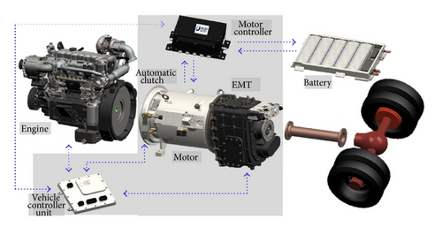
The powertrain system configuration of the single-axle parallel PHEB with EMT is shown in Figure 1. In electric mode the clutch is disengaged, while in other modes the clutch is engaged. Those components including the engine, the EMT, the clutch, and the electrical controller are all controlled by the vehicle control unit (VCU). The EMT without reverse gear has several forward gears and the vehicle can achieve reversing by the motor rotating reversely.
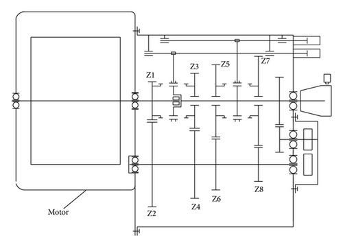
The configuration of a 4-gear EMT proposed in this paper is depicted in Figure 2. As shown in Figure 2, the EMT is composed of a motor, a mechanical transmission with three shafts, and a shift actuator. Instead of the synchronizer in traditional transmission, the EMT uses the gear clutch teeth to mesh and separate in the gear shifting process, which is helpful for reducing the axial size. In gear shifting process, the EMT can shift to the target gear by adjusting the speed of the transmission input shaft (also the motor shaft) during the speed synchronization phase.
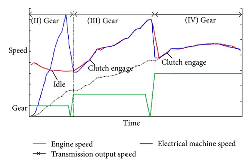
The gear shifting process of the PHEV with EMT is shown in Figure 3. The schematic diagram displays the vehicle starting with the 2nd gear and upshifting to the 4th gear continuously. When the vehicle starts, the engine is in an idle state and the clutch is disengaged; the EMT shifts to the 2nd gear; and the vehicle runs in a pure electric mode. As the motor speed increases to the upshift point, the EMT switches to the 3rd gear. After gear shifting, the vehicle still runs in the electric mode; when the engine and the motor are controlled to have the same rotating speed, the clutch is engaged. The vehicle is driven solely by the motor during the whole clutch engagement process. After the clutch is engaged, the vehicle switches to the hybrid mode (decided by the whole vehicle energy management strategy). When the speeds of the engine and the motor increase to the 3rd upshift point, the clutch is separated and the transmission shifts off to the neutral gear, and then the EMT starts to switch to the 4th gear, which shares the same principle with the shift from the 2nd gear to the 3rd gear.
3. Gear Shifting Quality Evaluation Indexes
The gear shifting quality evaluation indexes of the PHEV with EMT are power interruption time, shifting jerk [18, 19], and the service life of the shifting components.
3.1. Power Interruption Time
3.2. Gear Shifting Jerk
4. Control Algorithm Analyses for EMT Shifting
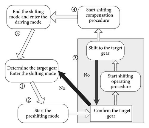
The gear shifting process of the single-axial parallel PHEV with EMT is shown in Figure 4. When the target gear is determined by the input conditions, the EMT switches to the shifting mode (step ① in Figure 4). The process starts with the preshifting procedure (step ② in Figure 4) determined by the torque request of the vehicle, which can make the vehicle transit to the shifting operating procedure smoothly. Then the EMT evaluates the target gear in real time according to the road condition and driver’s physical conditionbecause the preshifting phase has no power interruption (step ③ in Figure 4). When the target gear is confirmed, the EMT switches to the gear shifting operation procedure (the key of gearshift process). After shifting to the target gear, the EMT starts the shifting compensation procedure (step ④ in Figure 4), which compensates the torque request for the vehicle. With the finish of the phase ④, the shifting mode ends and is followed by the driver operating mode (step ⑤ in Figure 4). In the synthesis, the gear shifting process in a single-axle parallel PHEV with EMT is divided into five processes, forming the whole power process of driving and shifting. The concrete analysis of the gear shifting processes ② ③ ④ will be done below.
4.1. Preshifting Process
When the vehicle needs to shift to the new gear which is determined by the VCU, the powertrain switches to the shifting mode and starts the preshifting program. The system breaks off the shifting program only when the brake pedal is stamped by the driver. And then the system responds to the control strategies of the vehicle and gear shifting; otherwise the system switches to the shifting process smoothly. The main function of the preshifting program is to weaken the negative effects of the power interruption in the shifting process.
In the preshifting phase, the output torque of the power source (decided by the vehicle control strategies) is controlled by the control strategy of the driving force gradient.
4.2. Shifting Operation Process
- (a)
Disengage the clutch in the shortest time according to the indexes of the shifting jerk and the power interruption time; meanwhile, the motor switches to the idle mode with no torque output and the engine switches to the idle mode. Then the transmission switches to the neutral gear.
- (b)
In order to realize the speed synchronization of the input and output shafts, the motor adjusts the speed in torque control mode; meanwhile, the target speed of the motor is calculated.
- (c)
The transmission switches to the target gear when it meets the shifting requirements.
4.2.1. Shifting-Off Phase
4.2.2. Motor Active Speed Synchronization Phase
After switching to the neutral gear, start to reduce the speed difference between the shift sleeve and shift gear of the target gear, which is called motor active speed synchronization phase.
The sketch of the movement positions of the shift sleeve teeth in shifting process is shown in Figure 5. The red teeth represent the teeth of the shift sleeve while the blue ones represent those ofthe shift gear. A stands for the end of the active synchronization phase and B stands for the beginning of the gear meshing; C stands for the end of the gear meshing; ω1A, ω1B, and ω1C represent the rotating speed of the shift sleeve in stages A, B, and C, respectively; ω2A, ω2B, and ω2C represent the speed of theshift gear in stages A, B, and C, respectively.

4.2.3. Gear Meshing Phase
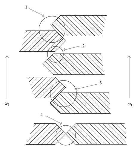
In this phase, the teeth of shift sleeve and those of shift gear begin to mesh. As shown in Figure 6, there are four different position relationships between the teeth of shift sleeve and those of shift gear in the gear meshing phase. The stages 2 and 4 are both special situations, representing small probability events, while the stages 1 and 3 appear in most cases. Although the causes of stages 1 and 3 are different, they have the same force situation. Take stage 1, for example, to analyze the force of the meshing teeth at the contact moment.
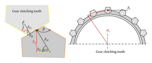
The teeth of shift sleeve and those of shift gear can mesh without failure when the following two conditions are satisfied: (1) Fk < Fa; (2) Mk < Ma.
The maximum shifting jerk occurs at the moment when the teeth of shift gear contact those of the shift sleeve. According to (32), we know that the gear shifting jerk is connected with the change of the synthetic speed difference.
4.3. Shifting Compensation Phase
In hybrid mode and engine mode, the clutch is engaged after this phase. Then the vehicle comes back to the driving mode which is controlled by the vehicle control strategies.
5. Simulation Analysis
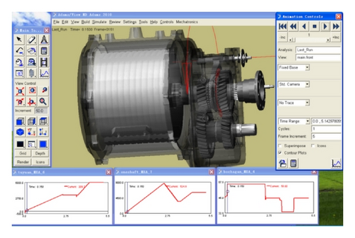
The gear shifting process of the hybrid electric drivetrain system is a sophisticated multi-rigid-body control system with complicated physical properties. So it is difficult to get the accurate shifting performance. Then let us analyze the control algorithm proposed above with the virtual prototype technology. The EMT model is simulated on the software ADAMS (Automatic Dynamic Analysis of Mechanical Systems). For simplifying the simulation model, the 4-speed EMT is replaced with a 2-speed EMT mode as shown in Figure 8.
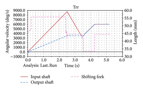
The simulation results of the speed and the shifting fork displacement response in the upshift process are shown in Figure 9. The EMT shifting control algorithm can satisfactorily meet the gearshift requirements. In the process of shifting from the 1st to the 2nd gear and when the speed of the input shaft is adjusted to approach the output shaft speed, the shifting fork starts moving, and the transmission shifts to the 2nd gear. During the whole gear shifting process, the speed fluctuation of each shaft is small and so is the shifting jerk.
By optimizing the simulation parameters, we can get various shifting results of different motor torques in speed synchronization phase, as shown in Table 1; the sampling frequency is 25 ms. The power interruption time is no more than 0.85 s. We can also notice that the greater the torque of the motor regulating speed is, the shorter the power interrupt time is; and also the shorter the power interrupt time is, the greater the shifting jerk will be. When the torque of the regulating speed is below the 100%, the power interruption time reduces with the increase of it, while when the torque of the regulating speed is over 100%, the power interruption time change is small. This is due to the fact that, with the increase of the torque of the motor speed adjustment, the gear meshing time is longer despite the fact that the shifting-off time and motor active synchronization time are shorter. According to the simulation results, we also know that, with the shifting control algorithm, the shifting jerk has been decreased and the shifting quality has been improved.
| Torque of the motor speed adjustment/% | Shifting-off time/ms | Motor active synchronization time/ms | Gear meshing time/ms | Power interruption time/ms | Shifting jerk/m/s3 |
|---|---|---|---|---|---|
| t2 | t3 | t4 | t | J | |
| 40 | 150 | 625 | 75 | 850 | 6.9 |
| 60 | 150 | 400 | 75 | 625 | 7.8 |
| 80 | 150 | 325 | 75 | 550 | 8.2 |
| 100 | 150 | 250 | 75 | 475 | 9.6 |
| 150 | 125 | 200 | 150 | 475 | 15.6 |
6. Bench Test and Road Test
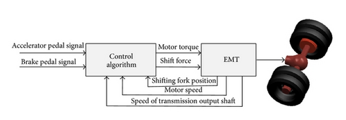
To verify the control algorithm for shifting a single-axle parallel PHEB equipped with EMT, the bench test and road test were conducted, respectively. The vehicle parameters are shown in Table 2. The shifting process control model is shown in Figure 10. The test bench picture is shown in Figure 11.
| Parameters | Value |
|---|---|
| Curb weight/full load gross mass/kg | 13000/18000 |
| Main reducer ratio | 6.2 |
| Transmission ration (4-gear) | 5.82; 3.23; 1.79; 1 |
| Engine displacement/L | 2.98 |
| Maximum power (kW)/speed (rpm) | 95/3200 |
| Maximum torque (Nm)/speed (rpm) | 345/1600~2400 |
| Motor | Induction motor |
| Rated/peak power (kW) | 80/160 |
| Maximum torque (N·m) | 954 |
| Lithium ion battery | |
| Capacitor (Ah)/rated voltage (V) | 160/576 |
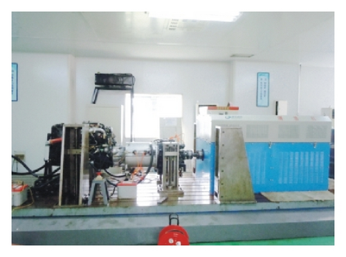
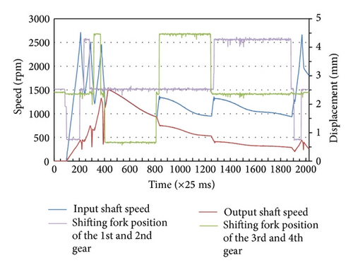
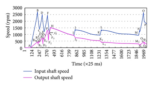
The control system of the dynamometer can display the output torque and speed of power sources in real time, and the shifting jerk of output shaft can be calculated simultaneously. The test results of the continuous upshift and downshift processes performed with the EMT in the bench test are shown in Figure 12. For analyzing the control algorithm, the test results of the output shaft speed and the input shaft speed are shown in Figure 13 with marks. As shown in Figure 13, the phases of BC (1st to 2nd), DE (2nd to 3rd), and FG (3rd to 4th) are the upshift processes, while those of IJ (4th to 3rd), KL (3rd to 2nd), and MN (2nd to 1st) are the downshift processes.
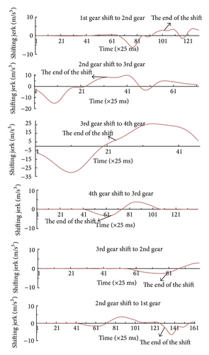
The bench test results of shifting jerk are shown in Figure 14. The results of power interrupting time and shifting jerk of each gear are shown in Table 3. As can be seen from the Table, the power interrupt time is controlled within 0.85 s, and the shifting jerk is controlled within 8.6 m/s3. The motor active synchronization phase takes about 70% of the power interrupt time, which is impacted by the torque of the motor speed adjustment.
| Gear change | t2/s | t3/s | t4/s | tPI/s | Maximum shifting jerk m/s3 |
|---|---|---|---|---|---|
| 1→2 | 0.12 | 0.53 | 0.11 | 0.76 | 5.2 |
| 2→3 | 0.10 | 0.61 | 0.10 | 0.81 | 8.1 |
| 3→4 | 0.09 | 0.64 | 0.12 | 0.85 | 8.6 |
| 4→3 | 0.09 | 0.46 | 0.10 | 0.65 | −3.9 |
| 3→2 | 0.09 | 0.50 | 0.14 | 0.73 | −3.2 |
| 2→1 | 0.10 | 0.45 | 0.13 | 0.68 | −4.7 |
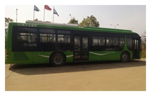
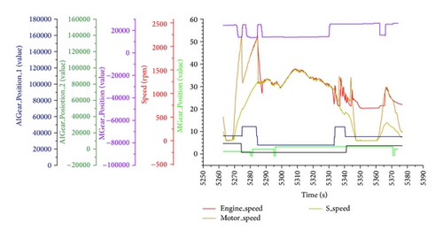
After plenty of bench tests, the road tests with a 12 m PHEV equipped with the EMT were conducted. The picture of the PHEB is shown in Figure 15. According to the control strategies, the test results of the engine speed, gear position sensor signals, clutch position sensor signals, motor speed, output shaft speed, and speed ratios are shown in Figure 16. The curves show the test processes in which the PHEB was starting with the 2nd gear and accelerating to the 4th gear and then decelerating and downshifting to the 2nd gear. The power interrupt time of the PHEB is less than 0.8 s, and the speed of the output shaft changes smoothly. The shifting jerk is no more than 10 m/s3 which meets the recommended reference value of the shifting jerk in Germany.
7. Conclusions
In this paper, the working principle of a single-axle parallel PHEV equipped with an EMT is described, and analysis of the shifting dynamics model in each transient process is also given in detail. Moreover, a new shifting control algorithm is introduced for improving the gearshift quality without synchronizer. With the control algorithm, the gears of the single-axle parallel PHEV equipped with the EMT can be controlled to engage faster and successfully without excessive wear on the gear surfaces. It is also important to note that the control algorithm was verified on a simulation platform by the bench test and PHEB test. All the results prove that adopting this control algorithm in parallel PHEV equipped with the EMT can improve the shifting quality significantly through its evaluation indexes, which is likely to help to replace the traditional AMT in HEV.
The EMT with proposed shifting control algorithm can also be applied to EVs and other kinds of HEVs to improve the shifting quality. In the near future, further study on EMT shifting will be carried on, and the new shifting algorithm will be proposed to improve the shifting quality further.
Conflict of Interests
The authors declare that there is no conflict of interests regarding the publication of this paper.
Acknowledgment
This work was supported by the National High Technology Research and Development Program of China (Grant no. 2011AA11A260).


