Parallel Jacobi EVD Methods on Integrated Circuits
Abstract
Design strategies for parallel iterative algorithms are presented. In order to further study different tradeoff strategies in design criteria for integrated circuits, A 10 × 10 Jacobi Brent-Luk-EVD array with the simplified μ-CORDIC processor is used as an example. The experimental results show that using the μ-CORDIC processor is beneficial for the design criteria as it yields a smaller area, faster overall computation time, and less energy consumption than the regular CORDIC processor. It is worth to notice that the proposed parallel EVD method can be applied to real-time and low-power array signal processing algorithms performing beamforming or DOA estimation.
1. Introduction
We are on the edge of many important developments which will require parallel data and information processing. The transmission systems are using higher and higher frequencies and the carrier frequencies are increasing to 10 GHz and above. Because of the smaller wavelength more antennas can be implemented on a single device leading to massive MIMO systems. Parallel VLSI architectures will be needed in order to provide the required computational power for 10 GHz and above, massive MIMO, and big data processing [1, 2].
In parallel matrix computation at the circuit level, implementing an iterative algorithm on a multiprocessor array results in a tradeoff between the complexity of an iteration step and the number of required iteration steps. Therefore, as long as the algorithm′s convergence properties are guaranteed, it is possible to adjust the architecture, which can significantly reduce the complexity with regard to the implementation. Computing the parallel eigenvalue decomposition (EVD) as a preprocessing step to MUSIC or ESPRIT algorithm with Jacobi′s iterative method is used as an important example as the convergence of this method is extremely robust to modifications of the processor elements [3–6].
In [7], it was shown that Brent-Luk-EVD architecture with a modified CORDIC for performing the plane rotation of the Jacobi algorithm can be realized in advanced VLSI design. Based on it, a Jacobi EVD array is realized by implementing a scaling-free microrotation CORDIC (μ-CORDIC) processor in this paper, which only performs a predefined number of CORDIC iterations. Therefore, the size of the processor array can be reduced for implementing a large-scale EVD array in parallel VLSI architectures. After that, several modifications of the algorithm/processor are studied and their impact on the design criteria is investigated for different sizes of EVD array (10 × 10 to 80 × 80). Finally, a strategy to comply with the design criteria is established, especially in terms of balancing the number of microiterations and the computational complexity. The proposed architecture is ideal for real-time antenna array applications, such as a flying object carrying an antenna array for beamforming or DOA estimation that would require a real-time, low-power, and efficient architecture for EVD, or joint time-delay and frequency estimation using a sensor network.
This paper is organized as follows. Serial and parallel Jacobi methods are described in Section 2. In Section 3, the design issues of the parallel Jacobi EVD array are discussed, leading to the simplification from a regular full CORDIC to the μ-CORDIC processor with an adaptive number of iterations. Section 4 shows the implementation results. Section 5 concludes this paper.
2. Parallel Eigenvalue Decomposition
2.1. Jacobi Method
2.2. Jacobi EVD Array
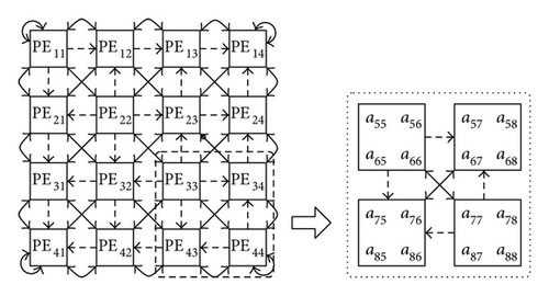
This optimal angle θopt, which can annihilate the off-diagonal elements (a2p−1,2q and a2p,2q−1), is computed using diagonal PEs in (6). Once these rotation angles are computed, they will be sent to the off-diagonal PEs. This transmission is indicated by the dashed lines in the vertical and horizontal direction in Figure 1. All off-diagonal PEs will perform a two-sided rotation with the corresponding rotation angles obtained from the row (θr) and column (θc), respectively.
Once these rotations are applied, the matrix elements are interchanged between processors as indicated by the diagonal solid lines in Figure 1, for the execution of the next n/2 rotations. One sweep needs to perform n − 1 of these parallel rotation steps. After several sweeps (iterations) are executed, the eigenvalues will concentrate in the diagonal PEs.
3. CORDIC Approach
3.1. Regular CORDIC
The CORDIC with an orthogonal vector mode can compute the arctangent result iteratively θ = arctan(y/x), if the angle accumulator is initialized with zero (z0 = 0).
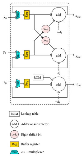
In the VLSI design, two common approaches can be used to realize the CORDIC dependence flow graph in hardware: the folded (serial) or the parallel (pipelining) [10, 11]. Note that we limit our efforts to the conventional CORDIC iteration scheme, as given in (7). In Figure 2(a), the structure of a folded CORDIC PE is shown, which requires a pair of adders for plane rotation and another adder for steering the next angle direction (computing the following zi and di). All internal variables are buffered in the registers separately until the iteration number is large enough to obtain the result. The signs of all three intermediate variables are fed into a control unit that generates the rotation direction flags di to steer the add or suboperations and keep track of the rotation angle zi. For example, off-diagonal PE43 can directly apply the flags di from PE33 to (8)’s G1 and PE44 to (8)’s G2. After the rotation, the required scaling procedure can be obtained using the part of Figure 2(b) that fixes An, where two multiplexers are required to select the inputs into the barrel shifters. This folded dependence graph is typical for the orthogonal rotation mode and benefits in a small area in the VLSI design.
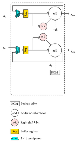
In practice, the angle accumulator is not required for the off-diagonal PEs. The di from (7) can be used to steer the rotators. Thus, the transmission on the vertical and horizontal dashed lines in Figure 1 will be replaced by a sequence of di flags, meaning that the off-diagonal computation efforts for computing the optimal angle θopt can be omitted.
3.2. Simplified μ-Rotation CORDIC
As the process technologies continue to shrink, it becomes possible to directly implement a Brent-Luk-EVD array with the Jacobi method [12, 13]. However, the size of the EVD array that can be implemented on the current configurable device with the regular CORDIC is still small, say, 4 × 4. Therefore, we must simplify the architecture in order to integrate more processors. A scaling-free μ-CORDIC for performing the plane rotation in (5) is used [5, 6], where the number of inner iterations is reduced from 32 iterations to only one iteration.
| Index | Type | Angle | Shift-add | Cycle | ||
|---|---|---|---|---|---|---|
| k | 2 × tanθ | rot. | sca. | cnt. | re. | |
| 1 | IV | 1.49070 | 4 | 8 | 6 | 1 |
| 2 | IV | 0.54296 | 4 | 6 | 5 | 1 |
| 3 | IV | 0.25501 | 4 | 6 | 5 | 1 |
| 4 | IV | 0.12561 | 4 | 4 | 4 | 1 |
| 5 | III | 6.25841 10−2 | 6 | 0 | 3 | 2 |
| 6 | III | 3.12606 10−2 | 6 | 0 | 3 | 2 |
| 7 | III | 1.56263 10−2 | 6 | 0 | 3 | 2 |
| 8 | II | 7.81266 10−3 | 4 | 0 | 2 | 3 |
| 9 | II | 3.90627 10−3 | 4 | 0 | 2 | 3 |
| 10 | II | 1.95313 10−3 | 4 | 0 | 2 | 3 |
| 11 | II | 9.76563 10−4 | 4 | 0 | 2 | 3 |
| 12 | II | 4.88281 10−4 | 4 | 0 | 2 | 3 |
| 13 | II | 2.44141 10−4 | 4 | 0 | 2 | 3 |
| 14 | II | 1.22070 10−4 | 4 | 0 | 2 | 4 |
| 15 | II | 6.10352 10−5 | 4 | 0 | 2 | 5 |
| 16 | I | 3.05176 10−5 | 2 | 0 | 1 | 6 |
| 17 | I | 1.52588 10−5 | 2 | 0 | 1 | 6 |
| 18 | I | 7.62939 10−6 | 2 | 0 | 1 | 6 |
| 19 | I | 3.81470 10−6 | 2 | 0 | 1 | 6 |
| 20 | I | 1.90735 10−6 | 2 | 0 | 1 | 6 |
| 21 | I | 9.53674 10−7 | 2 | 0 | 1 | 6 |
| 22 | I | 4.76837 10−7 | 2 | 0 | 1 | 6 |
| 23 | I | 2.38419 10−7 | 2 | 0 | 1 | 6 |
| 24 | I | 1.19209 10−7 | 2 | 0 | 1 | 6 |
| 25 | I | 5.96046 10−8 | 2 | 0 | 1 | 6 |
| 26 | I | 2.98023 10−8 | 2 | 0 | 1 | 6 |
| 27 | I | 1.49012 10−8 | 2 | 0 | 1 | 6 |
| 28 | I | 7.45058 10−9 | 2 | 0 | 1 | 5 |
| 29 | I | 3.72529 10−9 | 2 | 0 | 1 | 4 |
| 30 | I | 1.86265 10−9 | 2 | 0 | 1 | 3 |
| 31 | I | 9.31323 10−10 | 2 | 0 | 1 | 2 |
| 32 | I | 4.65661 10−10 | 2 | 0 | 1 | 1 |
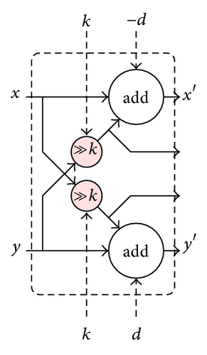
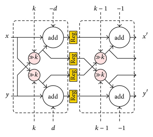
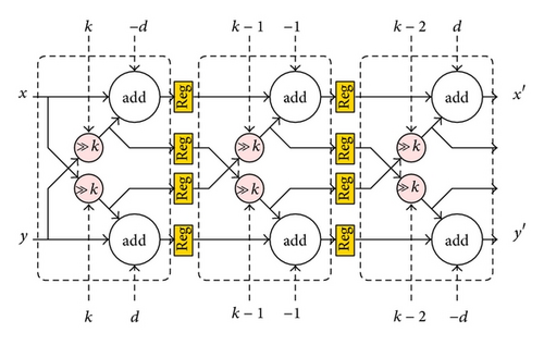
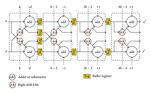
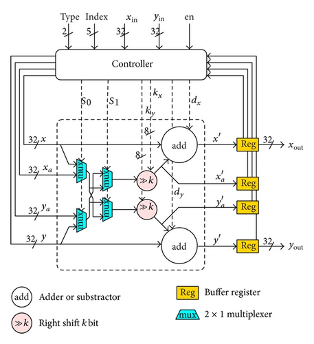
These four subtypes have three identical parts: Type I with one iteration, the scaling part of Type IV, and the second iteration of Type II. These three parts can be integrated together by using multiplexers to select the data paths, as shown in Figure 4, where 2 adders, 2 shifters, and 4 multiplexers are required [5].
3.3. Adaptive μ-CORDIC Iterations
To improve the computational efficiency, the μ-CORDIC has been modified to perform 6 iterations per cycle as CORDIC-6. As the global clock in a synchronous circuit is determined by the critical path, the maximum timing delay per iteration is 6 cycles (when the index k is 1, Type IV). Therefore, the inner iteration steps of the angles are repeated until they are close to the critical one. The required number of repetitions is quoted in Table 1. For example, when the rotation angle index k is 8, it will repeat three times from the index k = 8 to the index k = 10; when the rotation angle index k is 20, it is repeated six times from the index k = 20 to the index k = 25. On the other hand, we can adjust the number of iterations by selecting the average angle during the last sweep and name it as CORDIC-mean.
4. Experimental Results
4.1. Matlab Simulation
The full CORDIC with 32 iteration steps, the μ-CORDIC with one iteration step, and two different adaptive modes have been tested using numerous random symmetric matrices A of size 8 × 8 to 160 × 160 (i.e., EVD array sizes range from 4 × 4 to 80 × 80). Figure 5(a) shows the average number of sweeps needed to compute the eigenvalues/eigenvectors for each size of the EVD array, where the sweep number increases monotonically.
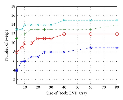
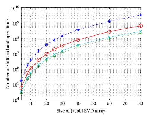
When the Jacobi EVD array size is 10 × 10, the μ-CORDIC requires 12 sweeps while the full CORDIC only requires 6 sweeps per EVD computation. If we adjust the inner rotations to six times, the sweep number will be 10, smaller than the μ-CORDIC but more than the full CORDIC. Note that using the average rotation angle to decide the rotation number as the CORDIC-mean seems to be an unwise method because it requires more sweeps. Although the μ-CORDIC requires double sweeps than the full CORDIC, it actually reduces the number of the inner CORDIC rotations, which results in improved computational complexity. For example, a 10 × 10 array with the Full CORDIC PE needs 6 sweeps × 32 inner CORDIC rotations and the CORDIC-6 needs 10 sweeps × 6 inner CORDIC rotations whereas the μ-CORDIC PE requires only 12 sweeps × 1 inner CORDIC rotation. In Figure 5(b), the average number of shift-add operations required for each rotation method for different sizes of EVD arrays is demonstrated whereas μ-CORDIC needs significantly fewer shift-add operations than others. The adaptive CORDIC-6 method can offer a compromise between the hardware complexity and the computational effort.
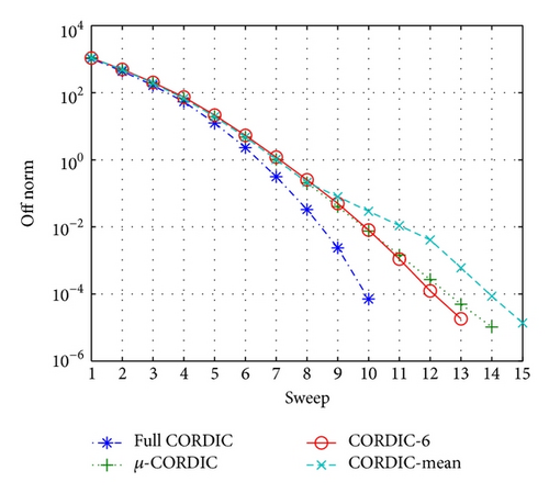
Figure 5(c) shows the off-diagonal Frobenius norm versus the sweep numbers for each array size of 80 × 80 with double floating precision. Each rotation method converges to the predefined stop criteria: . The is the Frobenius norm of the off-diagonal elements of A (i.e., Aoff = A − diag(diag(A))).
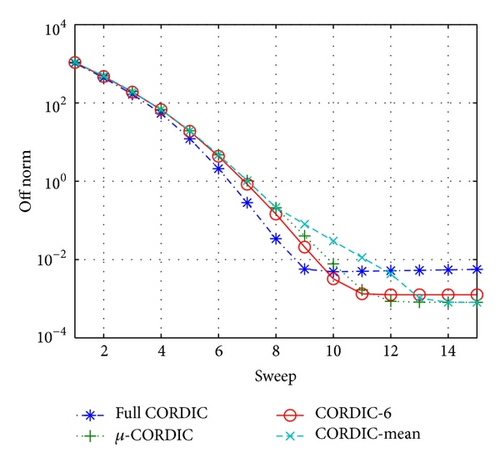
Figure 5(d) shows the reduction of the off-diagonal Frobenius norm versus the sweep numbers for single floating precision. It can be noticed that the off-norms do not reach the convergence criteria, and each size of the EVD array has different stop criteria for each rotation method (default IEEE 754 single). Therefore, we can first analyze the Frobenius norm of the off-diagonal elements in Matlab and then observe it until it reaches its maximal reduction. Afterwards, a lookup table can be generated and directly assign these stop criteria to the target hardware circuit or IP component.
4.2. VLSI Implementation
The μ-CORDIC is modeled and compared to the folded Full CORDIC in VHDL with the resizing feature. These two methods have been integrated into parallel EVD arrays, with sizes 4 × 4 and 10 × 10, through a configurable interface separately. After that, they have been synthesized by using the Synopsys Design Compiler with the TSMC 45 nm standard cell library. Note that the word length is 32 bits with the IEEE 754 single floating precision for both CORDIC methods using the same floating point unit from OpenCORE. Table 2 lists the synthesis results for area, timing delay, and power consumption.
| PE array size | Full CORDIC 4 × 4 | μ-CORDIC 4 × 4 | Full CORDIC 10 × 10 | μ-CORDIC 10 × 10 | |
|---|---|---|---|---|---|
| Area | Combinational | 0.847 mm2 | 0.296 mm2 | 5.143 mm2 | 1.829 mm2 |
| Noncombinational | 0.390 mm2 | 0.123 mm2 | 2.306 mm2 | 0.833 mm2 | |
| Total | 1.237 mm2 | 0.419 mm2 | 7.449 mm2 | 2.662 mm2 | |
| Power | Cell | 62.283 mW | 18.239 mW | 388.379 mW | 123.215 mW |
| Net | 0.465 mW | 0.433 mW | 2.993 mW | 2.678 mW | |
| Leakage | 11.909 mW | 3.765 mW | 86.136 mW | 23.966 mW | |
| Total | 74.657 mW | 22.437 mW | 477.508 mW | 149.859 mW | |
| Timing | Critical | 4.454 ns | 1.213 ns | 4.286 ns | 2.247 ns |
| Frequency | 224.5 MHz | 824.4 MHz | 233.3 MHz | 445 MHz | |
The total timing delay per EVD operation is defined by the critical timing delay × the number of inner CORDIC rotations × average number of outer sweeps × size of the matrix A. It can be observed that the total operation time is dependent on the relationship between the inner CORDIC rotations and the outer sweeps. Therefore, one obtains a speedup by a factor of 21.4 by reducing the number of inner CORDIC rotations. Although the reduction of power consumption is less significant due to an extra μ-CORDIC’s controller and multiplexers, it actually 6 consumes much less energy per EVD computation due to the shorter computation time. Note that the μ-CORDIC PE requires two inner iterations on average due to the different rotation cycles, from six to one inner iteration, as shown in Table 1. Figure 6 shows the energy consumption for sizes of the array from 4 × 4 to 80 × 80. Both rotation methods consume much less energy than the Full CORDIC, where the 6-CORDIC can obtain a factor of 40.9 and the μ-CORDIC can obtain a factor of 104.3 on average for energy reduction compared to the Full CORDIC.

In [14], a Jacobi single cycle-by-row EVD algorithm [15] has been implemented with a single CORDIC processor. Since it requires a very complex controller and lookup tables, the throughput is not comparable with a real Brent-Luk′s parallel EVD array [13]. In comparison to [13], Full CORDIC for Jacobi Brent-Luk-EVD parallel architecture is implemented in FPGA; however, current configurable device can only perform 4 × 4 EVD array. The experimental results show that performing the unitary rotation in CORDIC processor is a good solution. It required smaller area size, improved the overall computation time, and reduced the energy consumption. Furthermore, the unitary-rotation method can be also applied to other more efficient CORIDC architectures as long as the orthogonality is obtained during CORDIC iterations, such as pipeline CORDIC [16, 17], or implementing the rotators with better adder structures [18, 19].
As the process technologies continue to shrink, it becomes possible to directly implement a Brent-Luk-EVD array with the Jacobi method [12, 13]. However, the size of the EVD array that can be implemented on the current configurable device with the regular CORDIC is still small, say, 4 × 4. Therefore, we must simplify the architecture in order to integrate more processors. A scaling-free μ-CORDIC for performing the plane rotation in (5) is used [5, 6], where the number of inner iterations is reduced from 32 iterations to only one iteration.
5. Conclusions
The EVD was computed by the parallel Jacobi method, which was selected as an example for a typical iterative algorithm which exhibits very robust convergence properties. A configurable Jacobi EVD array with both Full CORDIC and μ-CORDIC is implemented in order to further study the tradeoff strategies in design criteria for parallel integrated circuits. The experimental results indicate that the presented μ-CORDIC method can reduce the size of the combinational logic, speed up the overall computation time, and improve the energy consumption.
Conflict of Interests
The authors declare that there is no conflict of interests regarding the publication of this paper.
Acknowledgment
The authors would like to thank the National Science Council of Taiwan for the support under the contract of NSC 101-2218-E-150-001.


