Motion Control of Four-Wheel Independently Actuated Electric Ground Vehicles considering Tire Force Saturations
Abstract
A vehicle stability control approach for four-wheel independently actuated (FWIA) electric vehicles is presented. The proposed control method consists of a higher-level controller and a lower-level controller. An adaptive control-based higher-level controller is designed to yield the vehicle virtual control efforts to track the desired vehicle motions due to the possible modeling inaccuracies and parametric uncertainties. The lower-level controller considering tire force saturation is given to allocate the required control efforts to the four in-wheel motors for providing the desired tire forces. An analytic method is given to distribute the high-level control efforts, without using the numerical-optimization-based control allocation algorithms. Simulations based on a high-fidelity, CarSim, and full-vehicle model show the effectiveness of the control approach.
1. Introduction
Electric vehicles typically achieve greater fuel economy, lower emissions, and increased energy security than conventional internal combustion engine vehicles [1]. Four-wheel independently actuated (FWIA) electric vehicles employ four in-wheel (or hub) motors to actuate the four wheels, and thus the torque of each wheel can be controlled independently. The actuation flexibility of the FWIA electric vehicles together with the fast and precise torque responses of electric motors enhances the vehicle control strategies, such as the traction control system and direct yaw-moment control [2–4].
The actuators in a FWIA electric vehicle are more than those in a conventional vehicle. This actuator redundancy makes the FWIA electric vehicle control problem more challenging but rewarding. This paper considers the motion control problems of FWIA electric vehicles. Both the vehicle longitudinal speed and yaw motion are controlled. Many studies have been carried out on the vehicle control methods for improving the vehicle stability and maneuverability. Most of them nevertheless are designed for the conventional vehicle architectures [5–7], not for the FWIA electric vehicles. Sakai et al. [8] proposed a direct yaw-moment control system for a FWIA electric vehicle, a half-vehicle model which is a linear approximation of vehicle dynamics was used in the controller design, and only the vehicle lateral motion was controlled. A braking control method for electric vehicle was proposed in [9], and the studied vehicle was driven by independent front and rear motors. The vehicle stability problem was not considered either in the paper. A stability control method for four-wheel driven hybrid electric vehicle was proposed in [10]. The studied vehicle in this paper was driven by a front and a rear motor, and the rear motor with an electrohydraulic brake was used to generate the required torque split for yaw motion control. As a FWIA electric vehicle is equipped with four in-wheel motors to independently actuate the four wheels, the control problem in [10] is thus different from the one considered in this study.
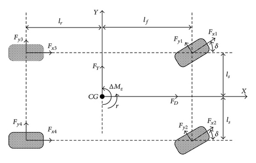
In this paper, the tracking control problem [11–14] of a FWIA electric vehicle is studied. The proposed control system consists of a higher-level controller and a lower-level controller. Due to the possible modeling inaccuracies and vehicle parametric uncertainties, an adaptive controller is designed as the higher-level control to give the required virtual total ground forces and the force split between the left and right sides of the vehicle. The vehicle longitudinal speed is controlled by the total ground forces while the yaw motion is compensated with the external yaw moment generated with the tire force difference between the two sides of the vehicle. The lower-level controller allocates the virtual ground forces from the higher-level controller to the four wheels. Control allocation algorithms are generally used to distribute the higher-level control signals to the lower-level actuators [15, 16]. As the control allocation algorithms usually require high computational costs, which may discourage their implementations in real time, an analytic solution of allocating the ground forces without using the numerical-optimization-based control allocation algorithms is given in this study. When the tire slip ratios become large and move into the unstable tire force region, the tire forces will be saturated and it may no longer be possible to fully transfer the desired tire force onto the road. What is more, locking/skidding wheels no longer provide any grip on the road and thus the cornering forces transferred to the ground will be limited. So the vehicle will be unsteerable if the tire slip ratios become too large. The constraints of the tire forces are also explicitly considered in the optimal solution.
The rest of the paper is organized as follows. System modeling is presented in Section 2. The proposed higher-level controllers are designed in Section 3. Tire force distribution design considering the tire force constraints is described in Section 4. Simulation results based on a high-fidelity, CarSim, full-vehicle model are provided in Section 5 followed by conclusive remarks.
2. System Modelling
3. Higher-Level Controller Design
4. Lower-Level Controller Design
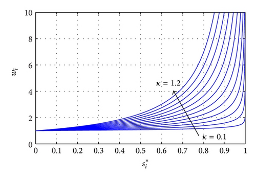
When the higher-level controller signals are obtained, the lower-level controller operates the four in-wheel motors such that the control requirements from the higher-level controller can be satisfied. An analytic solution is given to distribute the higher-level control efforts without using the numerical-optimization-based control allocation algorithms.
5. Simulation Results
Two simulation cases based on a high-fidelity, full-vehicle model constructed in CarSim were conducted. The vehicle parameters in the simulations were taken from an actual FWIA electric vehicle with in-wheel motors developed at the Ohio State University [21]. The desired vehicle yaw rate and speed can be generated from the drivers steering angle, accelerator/brake pedal positions. The vehicle reference model can be found in the literatures such as [22, 23].
5.1. J-Turn Simulation
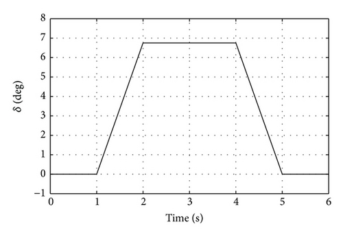
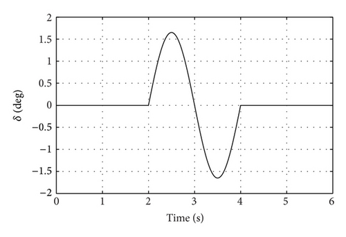
In this simulation, the vehicle ran at a low-speed range. A counter-clockwise turn was introduced with the front wheel steering angle shown in Figure 3. We aim at controlling the vehicle such that the actual vehicle states can follow the references. The nominal vehicle mass was set to 800 kg in the simulation. As the designed controller does not depend on the actual vehicle parameters, we set the vehicle mass in the controller as 600 kg, which is different than the actual vehicle mass.
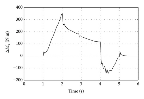
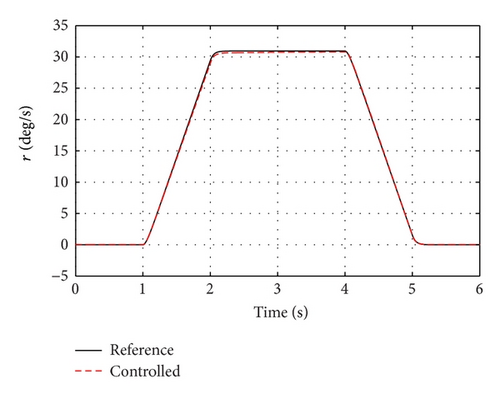
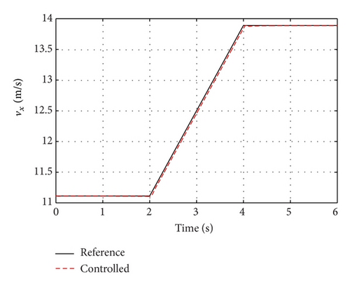
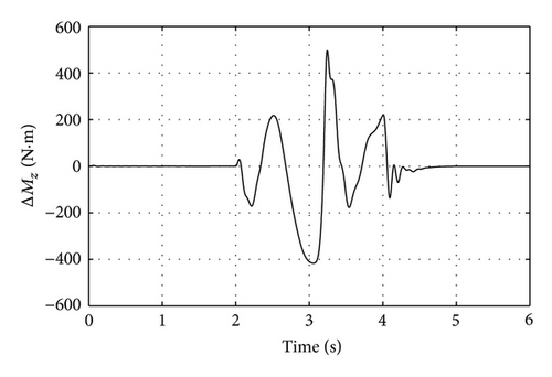
The generated external yaw moment with the tire force difference between two sides of the vehicle is shown in Figure 4. The vehicle yaw rate and vehicle speed are plotted in Figures 5 and 6, respectively. One can see from these two figures that both vehicle yaw rate and speed could be well controlled. Note that, in this simulation, a big steering angle was applied to the vehicle, and this steering angle could make the vehicle yaw rate reach up to 30 deg/s, which indicates that the proposed control method can control the vehicle well at extreme conditions.
5.2. Single-Lane Change
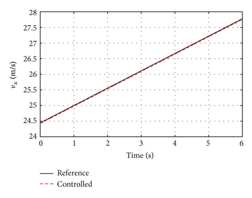
In the above simulation, we investigated the performance of the proposed controller in the cases where the vehicle runs on a high-μ road. In this simulation, the vehicle was controlled to make a single-lane change on a low-μ road. The tire-road friction coefficient was set as 0.2 and a big steering which would make the vehicle loss of stability was introduced at 2 s. The desired speed increased from 24.5 m/s to around 27.8 m/s in 6 seconds. The vehicle mass in the controller was set to 1000 kg, which is bigger than the actual vehicle mass.
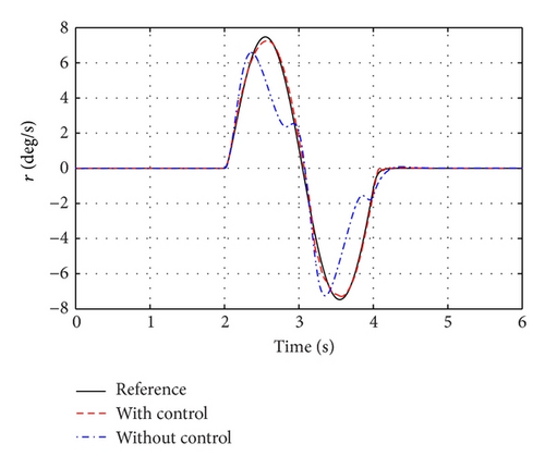
The front wheel steering angle is shown in Figure 7. The generated yaw moment which regulated the vehicle yaw rate was plotted in Figure 8. The yaw rate control results are shown in Figure 9. To better show the effectiveness of the proposed control method, the yaw rate of an uncontrolled vehicle which ran on the same low-μ road was compared. One can see from Figure 9 that the yaw rate of the controlled vehicle could always follow the reference, while the yaw rate of the uncontrolled vehicle deviated from the reference when the front wheel steering angle became large. The yaw rate control results indicate that stability of the controlled vehicle was ensured. The vehicle longitudinal speeds are plotted in Figure 10. One can see again that the vehicle speed could be well controlled as well.
6. Conclusion
A vehicle stability control system for an FWIA electric vehicle is presented. The proposed adaptive control-based higher-level controller does not need the accurate vehicle parameters or tire force models but can still yield the desired control signals. An analytic solution considering tire force constraints is designed to allocate the required control efforts from the higher-lever controller to the four wheels. Simulations under various driving scenarios are carried out with a high-fidelity, CarSim, and full-vehicle model. Simulation results show the effectiveness of the proposed control approach.
Conflict of Interests
The authors declare that there is no conflict of interests regarding the publication of this paper.
Acknowledgments
This paper was supported by National Science Foundation of China (51105074, 51205058, and 51375086), Foundation of State Key Laboratory of Mechanical Transmission (SKLMT-KFKT-201206), and by the Polish-Norwegian Research Programme operated by the National Centre for Research and 24 Development under the Norwegian Financial Mechanism 2009–2014 in the frame of Project Contract no. Pol-Nor/200957/47/2013.


