Generalized Outer Synchronization between Complex Networks with Unknown Parameters
Abstract
As is well known, complex networks are ubiquitous in the real world. One network always behaves differently from but still coexists in balance with others. This phenomenon of harmonious coexistence between different networks can be termed as “generalized outer synchronization (GOS).” This paper investigates GOS between two different complex dynamical networks with unknown parameters according to two different methods. When the exact functional relations between the two networks are previously known, a sufficient criterion for GOS is derived based on Barbalat′s lemma. If the functional relations are not known, the auxiliary-system method is employed and a sufficient criterion for GOS is derived. Numerical simulations are further provided to demonstrate the feasibility and effectiveness of the theoretical results.
1. Introduction
The past decade has seen many important achievements in the research of synchronization of complex networks. Most of this research has been focused on the coherent behavior within a network, where all the nodes within a network arrive at the same steady state [1–7]. This kind of synchronization, which was termed as “inner synchronization” [8], has attracted wide attention. However, in many real-world complex networks, there exist other kinds of synchronization, such as “outer synchronization” between two networks [8, 9], where the “complete outer synchronization” was studied under the assumption that all individuals in two networks have exactly identical dynamics. However, this kind of assumption may seem impractical. Take the predator-prey interactions in ecological communities as an example, where predators and preys influence one another’s behaviors. Without preys there would not be predators, while too many predators would bring the preys into extinction. The networks of predators and preys will finally reach harmonious coexistence without any man-made sabotage. It is worth noting that inside the networks of predators or preys, one individual always behaves differently from another. Thus it is more practical to assume that the nodes have different dynamics. Furthermore, the interaction patterns of predators themselves usually differ from those of preys; that is to say, the topological structure of the predators community is different from that of the preys community. There are a great many examples about harmonious coexistence between different real-world networks.
This kind of coexistence between different dynamical networks is termed as “generalized outer synchronization” [10], which represents another degree of coherence. As is known, due to parameter variation, various dynamics, or random perturbations, one individual always behaves differently from but still coexists in balance with others. That is to say, generalized synchronization widely exists. Particularly, it plays an important role in engineering networks [11–13], biological systems [10], social activities, and many other fields. Therefore, it is necessary and significant to investigate this kind of relationships between different dynamical networks.
Some recent work [10, 17–23] has studied generalized outer synchronization (GOS) in complex networks or complex systems, where the node dynamics parameters are known in advance. Nevertheless, in many practical situations, it is common that some system parameters cannot be exactly known in prior, and the synchronization will be destroyed and broken by the effects of these uncertainties.
Motivated by the above discussions, generalized outer synchronization between two dynamical networks with unknown parameters is investigated, where nodes in the two networks may have identical or different dynamics and the topological structures are different. Since the functional relations may be previously known or unknown, two kinds of generalized synchronization are considered.
The paper is organized as follows. In Section 2, GOS between two networks with predefined functional relations is investigated and the theoretical result is presented. In Section 3, based on the auxiliary-system method, GOS with unknown functional relations is studied. In Section 4, various numerical simulations are provided to demonstrate the feasibility and effectiveness of the theoretical results. A brief conclusion is drawn in Section 5.
2. GOS with Predefined Functional Relations
Definition 1. Let ϕi : Rn → Rm(i = 1,2, …, N) be continuously differentiable vector maps. The two networks (2) and (4) are said to achieve asymptotical generalized outer synchronization if
Assumption 2 (global Lipschitz condition). Suppose that there exist nonnegative constants Li (i = 1,2, …, N), such that for any time-varying vectors x(t), y(t) ∈ Rm, one has
When the functional relations ϕi : Rn → Rm(i = 1,2, …, N) are known, one arrives at the following theorem with the network models given above.
Theorem 3. Suppose that Assumption 2 holds. The dynamical networks (2) and (4) reach generalized outer synchronization as defined in Definition 1 with the following controllers:
Proof. Define ei = yi − ϕi(xi). From (2) and (4), one has
Consider the following Lyapunov candidate function:
Denote L = max {Li∣i = 1,2, …, N}. Let , , 𝒬 = C ⊗ Q, and let λm(·) be the largest eigenvalue of the matrix. Thus one has
Let
Obviously, , so V(t) is uniformly continuous. Furthermore, V(t) ≤ V(0)e−2t; that is, exists, then V(t) is integrable on [0, +∞]. According to Barbalat’s lemma, one gets lim t→∞V(t) = 0, thus lim t→∞ei(t) = 0 for i = 1,2, …, N. That is, networks (2) and (4) achieve generalized outer synchronization asymptotically. This completes the proof.
3. GOS with Unknown Functional Relations
Assumption 4 (global Lipschitz condition). Suppose that there exist nonnegative constants , such that
Theorem 5. Suppose that Assumptions 2 and 4 hold. Using the following controllers:
Proof. According to the auxiliary-system method, networks (2) and (4) achieve generalized outer synchronization if networks (4) and (15) reach complete outer synchronization. Define the synchronization error between (4) and (15) for the ith node as ei = zi − yi. Then the error dynamical systems can be described by
Let u(xi, zi) = −k(zi − xi) and u(xi, yi) = −k(yi − xi). Then the error dynamical systems can be rewritten into
Consider the following Lyapunov candidate function:
Let e, 𝒜, 𝒬, and λm(·) have the same meaning as that in the proof of Theorem 3, then it turns out
Taking
According to Barbalat’s lemma, networks (4) and (15) achieve complete outer synchronization; that is, networks (2) and (4) achieve generalized outer synchronization. This completes the proof.
4. Numerical Simulations
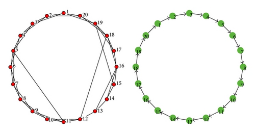
In this section, numerical simulations are carried out on networks consisting of 20 nodes to verify the effectiveness of the control schemes obtained in the preceding sections. Watts-Strogatz (WS) [25] algorithm is employed here to generate a small-world network. Specifically, start from a ring-shaped network with 20 nodes, with each node connecting to its 4 nearest neighbors. Then, rewire each edge in such a way that the beginning end of the edge is kept but the other end is disconnected with probability p and reconnected to another node randomly chosen from the network. In all the following simulations, a WS small-world network generated with rewiring probability p = 0.1, as shown in the left panel of Figure 1, is used as the topological structure for the drive network. Moreover, a directed ring network is employed as the structure of the response network, as shown in the right panel of Figure 1. The weight for every existent edge is supposed to be 0.01. For brevity, the inner-coupling matrices P and Q are taken as identity matrices with proper dimensions.
4.1. GOS with Known Functional Relations
4.1.1. GOS with Identical Node Dynamics
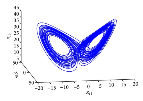
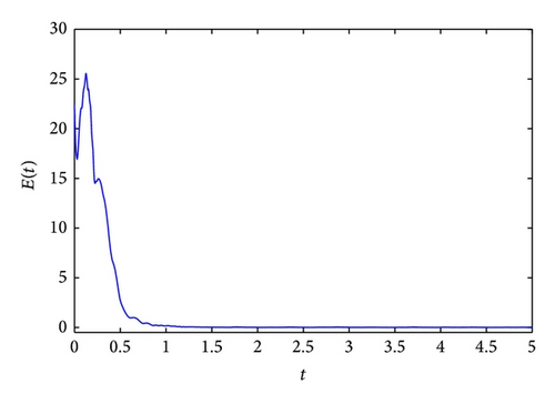
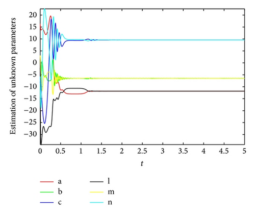
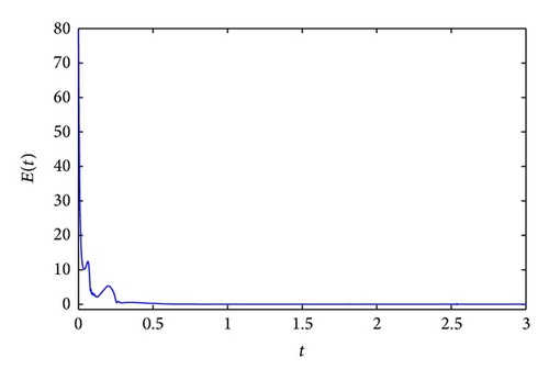
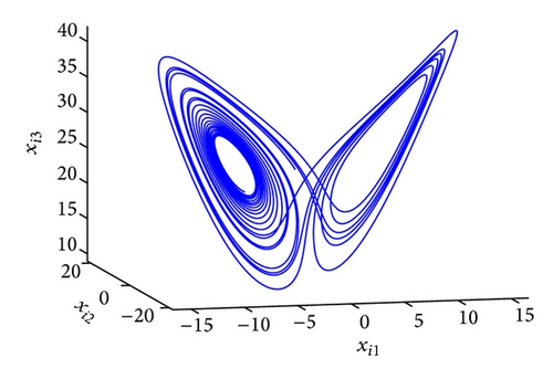
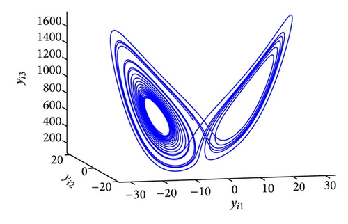
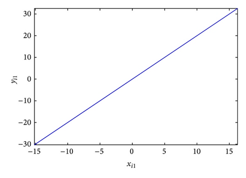
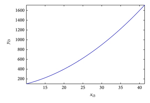
The GOS error E(t) = 〈∥yi − ϕi(xi)∥〉 between the drive and response networks is displayed in Figure 4. It is obvious that the two networks reach generalized outer synchronization with the proposed controller and updating laws (8). The phase diagrams of node 3 in both networks are displayed in Figure 5. Some corresponding subvariables of node 3 are also depicted in Figure 6, where transients are discarded. The relationships between dynamics of corresponding nodes in the two networks can be clearly observed.
4.1.2. GOS with Different Node Dynamics
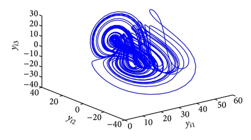
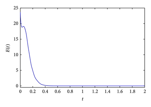
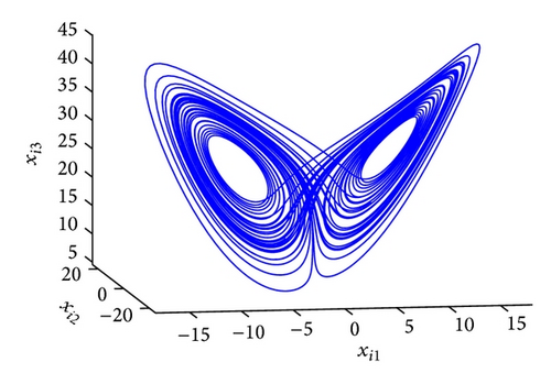
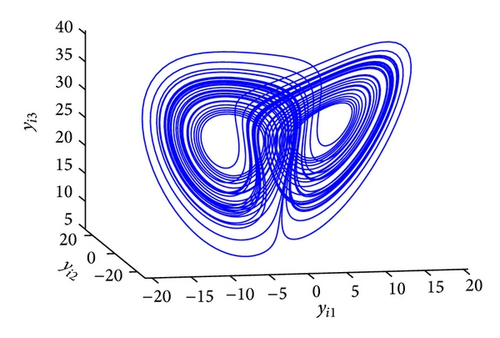
Figure 8 displays the GOS error E(t) = 〈∥yi(t) − ϕi(xi(t))∥〉 between the two different networks, with k = 100, r1 = r2 = 10. It is obvious that E(t) tends to zero after a short transient period. Figure 9 shows the dynamics of node 3 in the drive and response networks, where projections on different planes are displayed.

4.2. GOS with Unknown Functional Relations
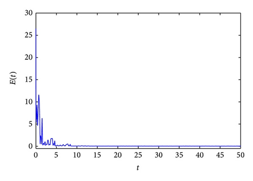
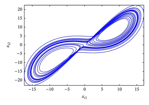
Let k = 20 in the controllers (17), and r = 10 in the updating laws (18). Figure 10 displays the synchronization error between the response and auxiliary networks, where E(t) = 〈∥zi(t) − yi(t)∥〉. One can see that when the control is imposed, the synchronization error quickly tends to zero, which means the existence of generalized outer synchronization between the drive and response networks. Figure 11 plots the dynamics of node 3 in the drive and response networks.
5. Conclusions
Research on generalized outer synchronization between complex networks has attracted wide attention in the past few years. To the best of our knowledge, few works focused on the case that the node dynamics parameters are unknown. In this paper, the generalized outer synchronization between two complex dynamical networks with unknown parameters has been investigated, with previously known or unknown functional relations. The feasibility and applicability of the theoretical findings have been validated by numerical simulations.
Acknowledgments
This work was supported in part by the National Natural Science Foundations of China (Grant nos. 61174028, 11172215, and 91130022) and in part by the Fundamental Research Funds for the Central Universities (Grant no. CZQ11010).


