Field Measurement of PV Array Temperature for Tracking and Concentrating 1 k Wp Generators Installed in Malaysia
Abstract
The effect of temperature elements for PV array with tracking and concentrating features installed in the tropical ground condition is presented. The temperature segment covers ambient temperature and surface and bottom temperature for three types of PV generator systems, namely, Fixed Flat (FF), Tracking Flat (TF), and Concentrating PV (CPV) generators. The location of measuring the cell temperature, Tc for the PV module is still being debated by researchers with the issue of how much the cell temperature (Tc) is being affected by the surface temperature (Ts), bottom temperature (Tb), and surrounding temperature (Ta) furthermore when it is located in fluctuating weather conditions. In this study, ΔT is calculated based on the difference between surface temperature and bottom-side temperaturewhichever the highest recorded at site for different kinds of PV generator systems but using the same CEEG 95 W monocrystalline PV module. The study embraces the direct correlation of various temperature elements in tropical-based condition with ΔT values of 2.19°C for FF module, 2.22°C for TF module, and 2.72°C for CPV module. These values which reflect the different unique configurations are further analyzed using multiple linear regression (MLR) and analysis of variance (ANOVA) test for Tarray models. This study supports the continuous research in adapting PV technology for Malaysia.
1. Introduction
Energy generation via photovoltaic technology and application has been the most economical viable green resources, especially in tropical-based countries [1–7]. Based on ground condition of the tropics with fluctuating environmental weather condition, temperature element is a crucial factor to be determined based on standard testing condition (STC) and nominal operating cell temperature (NOCT) equations.
Electricity generation is one of the biggest energy sectors utilizing a lot of fossil fuels as the main supply, and this contributes significantly to the emission of greenhouse gas (GHG) that pollutes the environment. Because of this adverse effect on the environment, the government of Malaysia under the Ministry of Energy, Green Technology and Water has introduced Green Technology initiatives to promote this technology application in the country. Malaysia which is located near the equator naturally has an abundance of sunshine which produces solar radiation. Although Malaysia enjoys a uniform temperature throughout the year, it is, however, extremely rare to have a full day with completely clear sky in various seasons even in periods of severe drought. On the average, Malaysia receives about 6 hours of direct sunshine per day where it is seasonal, and spatial variations are thus very much the same as in the case of sunshine [8–12].
Maximum radiation received during a sunny day produces peak power (Wp), where 90% of the extraterrestrial radiation becomes direct radiation, while the rest is being deflected as diffuse radiation [5].
This research intends to explore the effect of various temperature factors which correlates directly to the ground radiation level and crystalline PV energy generation. Two segments of temperature have been classified which are surface and bottom temperatures for three types of PV generator systems, namely, Fixed Flat (FF), Tracking Flat (TF), and Concentrating (CPV). The solar PV pilot plant with rated capacity of 10 kW is monitored, recorded, and analysed in real time via solar PV monitoring system (SPMS) using LabVIEW programming embedded in Compact Reconfigurable Input Output (cRIO) platform for system integration. The data have been collected for the duration of thirty consecutive days in June 2012.
1.1. Harvesting Energy from the Sun
Harvesting energy from the sun is a zero-carbon energy production activity where the sun reflects a solar fusion reactor emitting huge power of 63.11 MW. For every square metre surface the earth receives approximately 3.9 × 1024 J which is equivalent to 1.08 × 10¹⁸ kWh of solar energy annually [13]. This figure is about ten thousand times more than the annual global primary energy demand and much more than all available energy reserves on earth. Solar energy can be subdivided in two forms which are the direct and the indirect solar energy sources. Technical systems using direct solar energy convert incoming solar radiation directly into useful energy application for instance heat and electricity. Natural process systems using indirect solar energy convert solar energy into other types of energy before coming to the user application for instance, wind, river, and plant growth.
Baños et al. [14] define solar energy as radiant energy that is produced by the sun where in many parts of the world, direct solar radiation is considered to be one of the best prospective sources of energy. Direct solar energy applications are usually based on the building design and concept where an active design converts solar energy into electricity or heat by means of solar energy conversion system and contrarily a passive design utilizes the light energy from the sun for artificial lighting and heating. Based on MS IEC 61836:2010 [15], the photovoltaic panels are defined as PV modules which are mechanically integrated, preassembled, and electrically interconnected whereas photovoltaic system is assembly of components that produce and supply electricity by the conversion of solar energy.
Generally, a photovoltaic solar cell consists of two-layer semiconductor material which, in nonradiated condition, behaves like a diode whose I-V curve is traditionally described by the equation ID = I0 (exp (qVD/nkT) − 1) − IL where I0 is the reverse saturation current or leakage current of the diode, IL is the light generated current or the photocurrent, VD is the voltage accross diode is the reverse saturation current of the diode, q the electron charge (1.602 × 10⁻¹⁹ C), k the Boltzmann constant (1.381 × 10⁻²³ J/K), and T the junction temperature which depends on the kind of the semiconductor used [16].
Around the globe, research on photovoltaic cell and processing technologies are focusing on new approach to reduce cost via reducing the number of processing steps with high consideration of overall performance and efficiency [17]. Photovoltaic conversion can be defined as the direct conversion of pure energy sunlight into electricity without any heat engine to interfere as described by Parida et al. in [18]. Photovoltaic devices are rugged and simple in design requiring very little maintenance, and their biggest advantage is their construction as portable standalone systems to give outputs from microwatts to megawatts. MS IEC 61836:2010 defines PV conversion efficiency as ratio of maximum PV output to the product of PV device area and incident irradiance measured under specified test conditions usually at standard testing condition (STC).
1.2. Temperature Factor in PV Cell Equation
Skoplaki and Palyvos [19] explain the effect of temperature rise in the PV cell as the thermally excited electron begins to dominate the electrical properties of the semiconductor bands. Wu et al. [20] further supported the temperature rise effect towards PV energy performance due to losses created when lattice vibrations interfere with the free passing of charge carriers and the junction begins to lose its power to separate charges and proposes temperature-dependent charge controller devise for effective solution.
The importance and effect of radiation toward the energy generation in Oman have been studied by Gastli and Charabi [21] with the application of GIS-based solar radiation map. Power conversion efficiency and overall output power of the solar cells change with temperature and solar irradiance level, and this statement is further supported via conducting field study for four different types of solar panels in real performance under tropical weather condition.
A significant positive correlation between PV module temperature and spectral irradiance distribution parameter by means of energy production has been proven by Minemoto et al. [22] in which both parameters were characterized using contour plots. The influence of module temperature variations towards the energy efficiency which can be described using contour graph created from statistical analysis method based on average photon energy (APE) and field output factor (FOF) of the silicon PV Module has been analysed by Nagae et al. [23]. This technique also proves that temperature rise really affects the PV module performance ratio (PR) by producing contour graph for the temperature impact towards single-crystalline and amorphous silicon modules [24].
Skoplaki and Palyvos [25] found that there are other forms of heat energy transfer besides internal processes taking place within the semiconductor material during its bombardment by photons where convection mechanism in front and back sides of PV module panels plus heat conduction through mounting frames should be included in defining the energy balance. Park et al. [26] conducted a study to prove that there are such significant effects of the PV module’s thermal characteristics on its electrical generation performance building-integrated photovoltaic (BIPV) where approximately 0.5% reduction of energy generated based on 1°C increase of the module temperature. This statement is supported by Kim et al. [27] where they emphasize that through a proper method of cooling PV module by means of heat dissipation process using fins, interestingly, the energy efficiency from a common PV module usually falls at a rate of 0.5%/°C and it can be increased due to the drop in surface temperature especially on the highest heated portions of PV cell and ribbon where all means of cooling approach comes into the picture.
2. Experimental Procedures
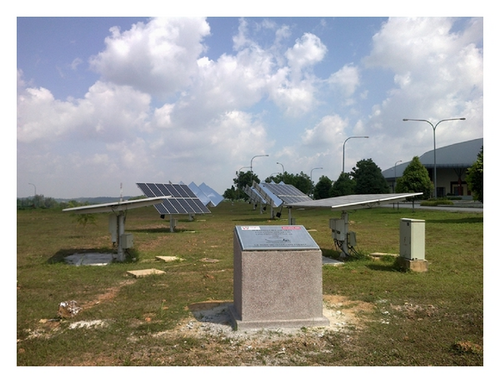
Three types of PV generator systems with a rated (at STC) capacity of 1 kW each with the total sum energy of 10 k Wp have been successfully configured in the Universiti Putra Malaysia (UPM), Serdang, Malaysia, at GPS coordinate of 2°59′20′′N:101°43′30′′E as illustrated in Figure 1. The PV system is equipped with precalibrated temperature sensors, one solar-radiation sensor and one wind-speed sensor. The temperature sensors are for measuring the ambient temperature (sensor located close to the PV arrays), the PV cell face temperature, and the PV cell bottom temperature.
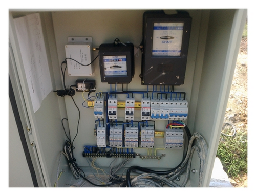
The system is directly connected to UPM electrical distribution line via Feeder Pillar (FP) which links to the main switch board (MSB) as shown in Figure 2. Grid-connected system ensures full capacity generation with assumption of the highest generator efficiency during the operation period compared to a standalone system which has some limitations. The ten units of PV generator are connected to three units of Aurora inverter system with the capacity of 2 × 3.6 kW and 6.0 kW for the purpose of Grid-tied operation.
The build-up areas for all PV generators are the same including the type of crystalline PV module used which is 3.6 m (L) × 2.4 m (W) × 2.8 m (H) with surface area of 8.64 m2. The differences between the 3 systems are quantity of PV module either 6 units or 12 units, tracking mechanism for 360° rotation (dual-axis), and concentrating mirror. The open-circuit voltage (Voc) for TF and FF is 270Vdc, while CPV generates 135Vdc. The short-circuit current (Isc) for all PV arrays is the same which is 5.56Adc.
Field evaluation and comparison of the temperature effect are verified via installation of 10 units of type-K thermocouple sensor at the surface and bottom side of each PV generator system. The other temperature elements of internal inverter temperature and surrounding temperature are taken directly from the weather station and Aurora inverter internal temperature sensor link to solar PV monitoring system (SPMS) as illustrated in Figure 3.
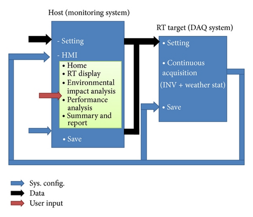
To achieve the research objective of investigating correlations of real-time and synchronize mode between temperature elements in PV system application, the data logging and monitoring process are done using NI compact RIO device (cRIO) platform with preembedded combination of LabVIEW programming to represent the overall system flow. The monitoring process is done continuously throughout the duration of 30 days in the month of June 2012 and the data for radiation (G) and ambient temperature (Ta) are described in Figure 4. The sample data is taken for the whole 30 days by 15-minute interval so as to show fluctuating pattern at a specific time of the day.
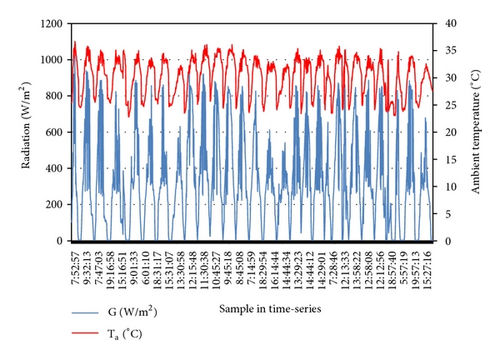
The fluctuation pattern of radiation, G, ranges from 3 W/m2 at 4.30 AM up to 1023 W/m2 at 2 PM which is the highest value in the month. On the other hand, ambient temperature fluctuates at the value of 22.8°C up to 36.7°C. The sun hours calculated for the whole month are 240 hours with 200 W/m2 as the minimum sun radiation reference.
3. Results and Discussion
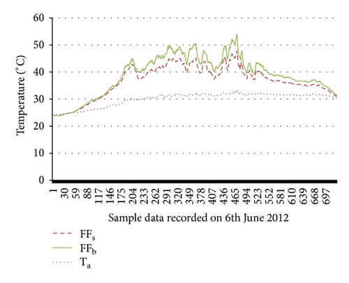
Sample data showing correlations between surface, bottom and ambient temperature is illustrated in Figure 5 with 700 samples of one-minute intervals.
The measured data for all temperature elements in this study is plotted with respect to radiation level at site as shown in Figure 6.
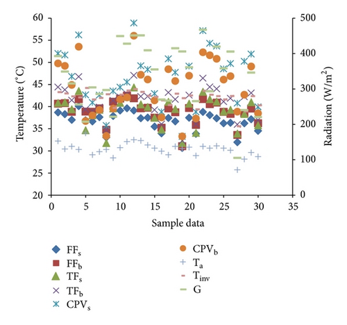
Based on Figure 6, the maximum value recorded for each temperature elements is 54°C for surface temperature, 48°C for bottom temperature, and 33.3°C for ambient temperature at the same time interval. The overall comparison of temperature elements for all 3 types of PV generator systems is described in Table 1 for average daily data with the highest temperature value comes from surface temperature of CPV generator.
| FFs (°C) | FFb (°C) | TFs (°C) | TFb (°C) | CPVs (°C) | CPVb (°C) |
|---|---|---|---|---|---|
| 38.68 | 40.67 | 40.82 | 44.43 | 52.01 | 49.76 |
| 38.29 | 40.8 | 40.96 | 43.8 | 51.67 | 49.21 |
| 36.99 | 38.83 | 39.37 | 41.47 | 46.84 | 44.91 |
| 40.09 | 41.69 | 43.53 | 46.79 | 56.2 | 53.54 |
| 35.49 | 37.52 | 37.49 | 39.27 | 42.96 | 41.4 |
| 33.95 | 35.25 | 34.79 | 36.07 | 38.83 | 37.56 |
| 37.42 | 39.58 | 41.07 | 43.19 | 50.8 | 48.45 |
| 36.65 | 38.75 | 39.44 | 41.65 | 47.73 | 45.78 |
| 30.65 | 31.08 | 31.76 | 32.28 | 33.26 | 33.3 |
| 37.49 | 39.69 | 40.65 | 42.61 | 49.15 | 46.99 |
| 36.22 | 38.81 | 38.89 | 41.15 | 48.54 | 46.1 |
| 36.33 | 38.37 | 39.27 | 41.89 | 49.74 | 46.89 |
| 31.94 | 33.61 | 33.89 | 36 | 40.8 | 38.86 |
| 36.22 | 38.46 | 38.35 | 42.23 | 50.26 | 42.7 |
| 37.13 | 39.57 | 40.98 | 43.1 | 51.87 | 49.07 |
| 34.53 | 36.25 | 35.77 | 37 | 39.98 | 38.49 |
For all the three types of PV generators, the surface and bottom temperatures fluctuate in the range from 30°C to 60°C which is an important value to determine cell or module temperature. For CPV generator, the surface temperature is much higher than the bottom value due to the mirror concentrating effect of heat convection. The surrounding or ambient temperature fluctuates in the range from 25°C to 33°C which reflects the nominal operating cell temperature (NOCT) in MS/IEC Standards with an average daily value of 29.56°C.
Based on the average daily data analysis, the relationship between surface temperature (Ts) and the bottom temperature (Tb) are described in Table 2.
| Temperature effect | Comments | |
|---|---|---|
| Fixed Flat PV generator |
|
Most researchers adapt the bottom-side values as the cell/module temperature for crystalline PV due to the higher temperature value |
| Tracking Flat PV generator |
|
The same concept as above. The tracking mechanism which receives peak radiation level most of the time results in higher bottom temperature values compared to FF generator |
| CPV generator |
|
The uniqueness of adapting two elements of tracking mechanism and mirror concentrator creates much higher value on the surface side of the PV module which contradicts the normal concept of Tc |
Furthermore, based on MLR and ANOVA test, PV array temperature model with respect to the radiation and ambient temperature is described as follows:
4. Conclusion
Review and field analysis on correlation between four temperature elements are presented. It was concluded that all temperature elements discussed have significant contribution either direct or indirect influences which affect the performance of photovoltaic generator system in providing sufficient energy supply. It is a known fact that PV conversion process does produce heat as energy wastage and PV module efficiency degrades with the increase in temperature which usually falls at a rate of 0.5%/°C. The highest ΔT value comes from the CPV array with the surface side producing higher heat energy. This study shares some findings of linearly correlated Tarray model with respect to radiation and ambient temperature for three types of uniquely configurated PV arrays installed in the tropics.
Nomenclature
-
- DART:
-
- Data acquisition and real-time
-
- cRIO:
-
- Compact reconfigurable input output
-
- SPMS:
-
- Solar PV monitoring station
-
- Gref:
-
- Reference radiation value of 1000 W/m2
-
- GT:
-
- Measured radiation value in W/m2
-
- Ta:
-
- Ambient temperature
-
- Tc:
-
- Cell temperature
-
- Tm:
-
- Module temperature
-
- Tarray:
-
- Array temperature
-
- FFs:
-
- Surface temperature for fixed flat PV generator
-
- FFb:
-
- Bottom-side temperature for fixed flat PV generator
-
- TFs:
-
- Surface temperature for tracking flat PV generator
-
- TFb:
-
- Bottom-side temperature for tracking flat PV generator
-
- CPVs:
-
- Surface temperature for concentrating PV generator
-
- CPVb:
-
- Bottom-side temperature for concentrating PV generator
-
- SE:
-
- Standard error
-
- NI:
-
- National instrument
-
- ANOVA:
-
- Analysis of variance
-
- MLR:
-
- Multiple linear regression
-
- R2:
-
- Significant correlation factor
-
- DAQ:
-
- Data acquisition
-
- RT:
-
- Real time
-
- HMI:
-
- Human machine interface.
Acknowledgments
The authors would like to thank Sichuan Zhonghan Solar Power Co. Ltd for the generous support on setting up the PV pilot plant, assisting in data monitoring and analysis and sharing of technologies throughout the research process. Furthermore, they delegate their thanks to the Research Management Centre (RMC), Universiti Putra, Malaysia, for the approval of research funding under the Project Matching Grant (Vote no.: 9300400) and Ministry of Higher Education, Malaysia, for the approval of Fundamental Research Grant Scheme (FRGS Vote no.: 5524167).
Appendix
See Table 3.
MLR and ANOVA Test. See Tables 4, 5, 6, and 7.
| Electrical typical data | CEEG CSUN 95W-36M |
|---|---|
| Pmpp [W] | 95 |
| Voc [V] | 22.5 |
| Isc [A] | 5.56 |
| Vmpp [V] | 18.3 |
| Impp [A] | 5.21 |
| Practical module efficiency | 17.05% |
| Voltage temperature coefficients | −0.307%/K |
| Current temperature coefficients | +0.039%/K |
| Power temperature coefficients | −0.423%/K |
| Series fuse rating [A] | 10 |
| Cells 4 × 9 @ 36 pieces monocrystalline solar cells series strings | 125 mm × 125 mm |
| Junction box | with 2 bypass diodes |
| Cable | length 600 mm, 1 × 4 mm2 |
| Front glass | White toughened safety glass, 3.2 mm |
| Cell encapsulation | EVA (Ethylene-Vinyl-Acetate) |
| Back sheet | composite film |
| Frame | Anodised aluminium profile |
| Dimensions |
|
| Maximum surface load capacity | 2,400 Pa |
| Hail | Maximum diameter of 25 mm with impact speed of 23 m·s−1 |
| Temperature range | −40°C to +85°C |
| Regression statistics | |
|---|---|
| Multiple R | 0.987429459 |
| R Square | 0.975016936 |
| Adjusted R Square | 0.972134275 |
| Standard error | 0.444029697 |
| Observations | 30 |
| df | SS | MS | F | Significance F | |
|---|---|---|---|---|---|
| Regression | 3 | 200.0616483 | 66.68722 | 338.235 | 6.10857E − 21 |
| Residual | 26 | 5.126221676 | 0.197162 | ||
| Total | 29 | 205.18787 | |||
| Coefficients | Standard error | |
|---|---|---|
| Intercept | −1.678085319 | 2.015645509 |
| Ta | −0.117136967 | 0.071238145 |
| Radiation (G) | 0.001492943 | 0.001202588 |
| FFs | 1.188748497 | 0.04219168 |
| Regression statistics | |
|---|---|
| Multiple R | 0.97275466 |
| R Square | 0.946251629 |
| Adjusted R Square | 0.940049894 |
| Standard error | 0.885232775 |
| Observations | 30 |
| df | SS | MS | F | Significance F | |
|---|---|---|---|---|---|
| Regression | 3 | 358.698573 | 119.5662 | 152.5785 | 1.2743E − 16 |
| Residual | 26 | 20.37456371 | 0.783637 | ||
| Total | 29 | 379.0731367 | |||
| Coefficients | Standard error | |
|---|---|---|
| Intercept | −9.503340876 | 4.063070816 |
| Ta | 0.356280226 | 0.135307719 |
| Radiation (G) | −0.006620823 | 0.002569022 |
| TFs | 1.080144819 | 0.056718604 |
| Regression statistics | |
|---|---|
| Multiple R | 0.977883672 |
| R Square | 0.956256475 |
| Adjusted R Square | 0.951209145 |
| Standard error | 1.417568074 |
| Observations | 30 |
| df | SS | MS | F | Significance F | |
|---|---|---|---|---|---|
| Regression | 3 | 1142.14649 | 380.7155 | 189.4579 | 8.80068E − 18 |
| Residual | 26 | 52.24698035 | 2.009499 | ||
| Total | 29 | 1194.39347 | |||
| Coefficients | Standard error | |
|---|---|---|
| Intercept | −4.542469701 | 6.027512011 |
| Ta | 0.232758421 | 0.216798907 |
| Radiation (G) | −0.006474561 | 0.004029298 |
| CPVb | 1.053363488 | 0.048316856 |
| Regression statistics | |
|---|---|
| Multiple R | 0.934929786 |
| R Square | 0.874093704 |
| Adjusted R Square | 0.864767312 |
| Standard error | 0.650565694 |
| Observations | 30 |
| df | SS | MS | F | Significance F | |
|---|---|---|---|---|---|
| Regression | 2 | 79.33350216 | 39.66675 | 93.72259708 | 7.08991E − 13 |
| Residual | 27 | 11.4273645 | 0.423236 | ||
| Total | 29 | 90.76086667 | |||
| Coefficients | Standard error | |
|---|---|---|
| Intercept | 14.03251613 | 2.691542602 |
| Ta | 0.867171815 | 0.099396709 |
| Radiation (G) | 0.004692967 | 0.00174276 |


