SPICE Mutator Model for Transforming Memristor into Meminductor
Abstract
The memristor (resistor with memory), as the fourth fundamental circuit element, is a nonvolatile nanoelectronic device and holds great promise for VLSI applications. It was suggested that the meminductor (ML, inductor with memory) circuit can be built by memristor emulators. This paper further addresses the transformation mechanism in terms of constitutive relation from the memristor to the meminductor and then designs an MR-ML mutator to achieve MR-ML transformation. We also present the mutator’s SPICE model and analyze the simulation results.
1. Introduction
The memristor (a contraction for memory resistor) was believed to be the fourth fundamental two-terminal passive element, besides the resistor, the capacitor, and the inductor. The element was firstly postulated by Chua [1] to characterize the relationship between the charge and the flux linkage for the sake of the completeness of the circuit theory. However, this pioneer work had not attracted the researchers’ attention until 2008. Strukov et al., at Hewlett Packard, announced the first experimental design of memristor—two TiO2 layers sandwiched between two platinum electrodes [2]. This work has been causing a tremendously increased interest in the field of the theory and applications of the memristor. Progressive potential applications of memristor cover many important areas, such as digital memory logic, analog circuits, and neural synapse [1, 3–7].
The memristor is a special case of a more general memristive system which was defined by Chua and Kang [8]. In 2009, the memcapacitatative and meminductive systems were also formulated in the spirit of memristive systems. As the special types of the memcapacitive and meminductive systems, memcapacitor and meminductor [9] also attract interest of the scientists. Combining with memristive systems, these elements will open up much new and unexpected functionality in the field of electronics [10].
Recently, several emulator models for meminductor and memcapacitor were built [11, 12]. However, these emulator models are complicated for circuit implementation. To conquer this problem, we present a design method of mutator for MR-ML transformation, which makes the circuit realization and theoretical analysis much more convenient and effective. This method can apply easily to build the mutator for MR-MC transformation. In the next section, we will analyze the constitutive relation of meminductor via CR transforming method. Then, the idea for transforming MR to ML is proposed in Section 3. Based on the SPICE model of the memristor, the mutator model for meminductor will be designed in Section 4, and then simulation and analysis results are demonstrated in Section 5. Finally, the conclusions are drawn in Section 6.
2. Constitutive Relation of Meminductor
3. Transformation from Memristor to Meminductor
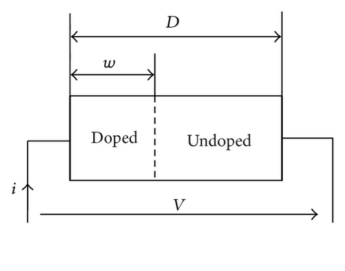
In this paper, we use the memristor model proposed in [14] to demonstrate the theoretical possibility of transforming the memristor into the meminductor.
Hence, we have obtained the constitutive relation of meminductor ρ(q) (12) and the meminductance (13) LM(q) upon expanding the constitutive relation of the memristor.
4. Mutator from MR into ML
4.1. Characterization of the MR-ML Mutator
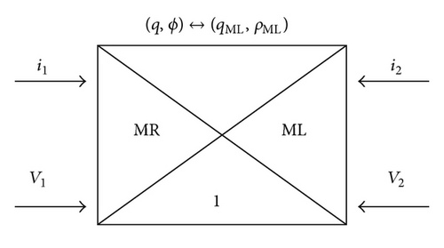
The mutator is an active, two-port linear network for transforming one type of nonlinear element into another type. There are three types of mutators—an L-R mutator, a C-R mutator, and an L-C mutator—which have been realized [17]. In this subsection, we introduce an MR-ML mutator which is firstly proposed in [15, 18]. It is characterized by the property that if a nonlinear memristor with a v–i curve γ is connected across port 2 of this element, the resulting one port (seen across port 1) becomes a nonlinear inductor in the sense that it can be characterized by a ϕ-i curve which is identical to the original v-i curve γ. The basic principle of a mutator is as shown in Figure 2.
4.2. Demonstration by Example
4.3. Realization of MR-ML Mutator Model
- (i)
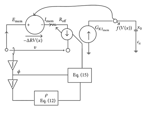
The terminal voltage of mutator is sensed and led to a cascade of two time-domain integrations in order to get the flux(ϕ) and the TIF(ρ).
- (ii)
Based on the knowledge of the charge and TIF, the meminductance is computed from (13).
- (iii)
Based on the knowledge of the LM(q) and ϕ, the current i of the meminductor mutator can be computed as follows:
()
5. Simulation Results
To verify the effectiveness of the proposed mutator, SPICE simulation is designed and simulation results with series waveforms demonstrate its performance. The run time is set as 2 s. We connect the sinusoidal current source as the excitation of the circuit. The voltage and the current flow through the memristor as the excitation of e port 1.
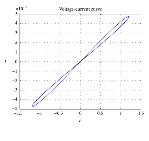
Consider the memristor model shown in Figure 1 with the parameters RON = 100, ROFF = 16 K, Rinit = 11 k, D ≈ 10 nm, and uv ≈ 10−14 m2 s−1 V−1. As used in [12], the window function is chosen as a smoother Joglekar function with the parameter p = 1. We use the sinusoidal voltage source, with the parameter of the peak amplitude Va = 1.4 V, and the frequency freq = 0.325 HZ. The V-I characteristic of memristor is presented in Figure 4.
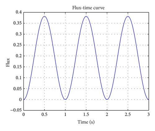
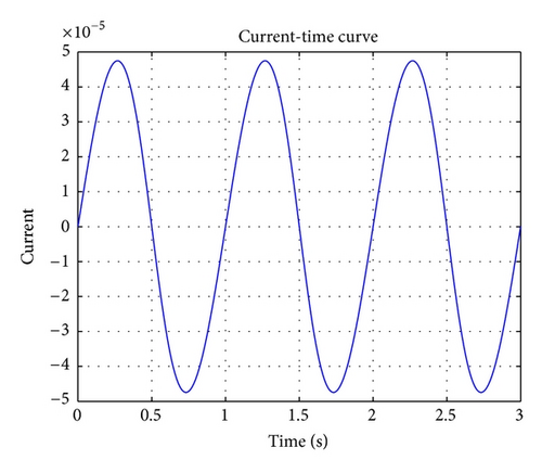
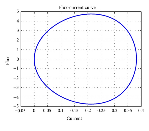
The ϕ(t) curve and the i(t) curve of port 1, which are used to characterize the property of the meminductor, are shown in Figures 5(a) and 5(b). Figure 5(a) represents the flux of the meminductor, and Figure 5(b) represents the current, respectively. Figure 6 shows the meminductance LML(LML = ϕ(t)/i(t)) curve.
6. Conclusions
We have demonstrated that the current-controlled meminductor can be transformed into memristor through the constitutive relation expanding. The mutator presented here provides a true MR-ML transformation. Using the procedure mentioned above, the memristor-to-memcapacitor mutator can also be easily designed. Together with the recently reported mutator, these circuits serve as useful tools for analyzing these new memory elements.
Acknowledgments
This work was supported in part by the National Natural Science Foundation of China under Grant 60974020, 60972155, the Natural Science Foundation of Chongqing under Grant CSTC2009BB2305, the Fundamental Research Funds for the Central Universities (Grant no. XDJK2010C023), and the National Science Foundation for Post-doctoral Scientists of China (Grant no. CPSF20100470116).


