The Effects of Control Domain Position on Optimal Control of Cardiac Arrhythmia
Abstract
We study the effects of control domain position on optimal control problem of cardiac arrhythmia. The well-established mathematical model, namely, the monodomain model, is used to represent the electrical behavior of the cardiac tissue. Two test cases are considered in this paper: the control domain for Test Case 1 is close to the excitation domain, while the control domain for Test Case 2 is a little bit far away from the excitation domain. The modified Dai-Yuan nonlinear conjugate gradient method is employed for computing the optimal applied extracellular current. Our experiment results show that the excitation wavefronts are successfully dampened out for both test cases. Also, experiment results show that the position of the control domain for Test Case 1 is preferable than that of Test Case 2 during the defibrillation process.
1. Introduction
Cardiac arrhythmia refers to the condition in which normal heart rhythm is disrupted. During arrhythmia, the heart may beat too rapidly, too slowly, or even irregularly. This abnormal and irregular heart rhythm causes the heart muscle to fibrillate and stops pumping blood to the body and the brain. Eventually, death can occur within minutes unless the normal heart rhythm is restored. For prevention of this sudden cardiac death, the only effective therapy is through electrical defibrillation [1–3].
The optimal control approach to cardiac arrhythmia was first proposed by Nagaiah et al. [4] with the control objective being dampen the excitation wavefront of the transmembrane potential using optimal applied extracellular current. Since the monodomain model is chosen by Nagaiah et al. [4] for representing the electrical behavior of the cardiac tissue, we, therefore, call it optimal control problem of monodomain model in the rest of the paper.
The optimal control problem of monodomain model is a PDE-constrained optimization problem that is constrained by the monodomain model. The monodomain model is a well-established mathematical model extensively used for simulation of cardiac electrical activity [5–7]. It consists of a parabolic partial differential equation (PDE) coupled to a system of nonlinear ordinary differential equations (ODEs) representing cell ionic activity.
Three classical nonlinear conjugate gradient methods have been employed by Nagaiah et al. [4] for solving the optimal control problem of monodomain model, namely, the Dai-Yuan (DY) method [8], the Hager-Zhang (HZ) method [9], and the Polak-Ribière-Polyak (PRP) method [10, 11]. Later, the optimal control problem of monodomain model has been subsequently studied by researchers with attempt to develop efficient numerical solving techniques [12–14].
Recently, the effects of the size of the control domain on the optimal control problem of monodomain model have been studied by Ng and Rohanin [15]. Two test cases with different sizes of the control domain are considered, and their numerical results show that higher extracellular current is required in the dampening process when the size of the control domain changed to a smaller one. Also, longer time is needed to dampen out the excitation wavefront when small size control domain is used.
In this paper, we are concerned with the effects of the control domain position on the optimal control problem of monodomain model. Again, two test cases are considered with each one of them located at different positions. The indirect method, also known as the optimize-then-discretize approach is used to discretize the optimal control problem. The discretized optimal control problem is then solved by the modified nonlinear conjugate gradient method, namely, the modified Dai-Yuan (MDY) method. As shown in [13], the MDY method is well performed under Armijo line search.
The outline of this paper is as follows. In Section 2, we introduce the optimal control problem of monodomain model with Rogers-modified FitzHugh-Nagumo ion kinetic. In Section 3, we present the numerical approach used to discretize the optimal control problem. In Section 4, we discuss the optimization procedure used to solve the discretized optimal control problem. In Section 5, we present and compare the experiment results for both test cases. In Section 6, we conclude our paper with a short discussion.
2. Optimal Control Problem of Monodomain Model
Note that (2.1) is the cost functional, in which the transmembrane potential V and the ionic current variable w act as the state variables and the extracellular current Ie acts as the control variable. Also, the control variable Ie is restricted to be nontrivial only on the control domain Ωc. The monodomain model, as defined in (2.2), appears as the PDE constraints in the optimal control problem of monodomain model. Next, the boundary and initial conditions for this optimal control problem are given in (2.3), and, lastly, (2.4) is taken from the Rogers-modified FitzHugh-Nagumo model [16].
3. Discretization of the Optimal Control Problem
4. Optimization Procedure
4.1. Optimization Algorithm
Step 1. Provide an initial guess and set k = 0.
Step 2. Solve the discretized state system in (3.12) for time interval [0, T] as follows.
- (a)
Solve the linear PDE for t ∈ [t, t + Δt/2]
() - (b)
Solve the nonlinear ODEs for t ∈ [t, t + Δt]
() - (c)
Solve the linear PDE for t ∈ [t + Δt/2, t + Δt]
() -
where Δt is the global time step.
Step 3. Evaluate the reduced cost functional .
Step 4. Solve the discretized adjoint system in (3.13) for time interval [T, 0] as follows.
- (a)
Solve the linear PDE for t ∈ [T, T − Δt/2]
() - (b)
Solve the nonlinear ODEs for t ∈ [T, T − Δt]
() - (c)
Solve the linear PDE for t ∈ [T − Δt/2, T − Δt]
()
Step 5. Update the reduced gradient using (3.9).
Step 6. For k ≥ 1, check the following stopping criteria:
If one of them is met, stop.
Step 7. Compute the conjugate gradient update parameter using (4.3).
Step 8. Compute the search direction dk using (4.2).
Step 9. Compute the step length δk that satisfies the condition in (4.5).
5. Numerical Experiments
5.1. Experiment Setup
A two-dimensional computational domain of size 1 × 1 cm2, that is, Ω = [0,1] × [0,1] is considered in our numerical experiments, and the final simulation time is set to be T = 2 ms. Figure 1 displays the positions of the subdomains in the computational domain Ω for Test Case 1 and Test Case 2. As shown in the figures, Ωc1 and Ωc2 are the control domains, and are the neighborhoods of the control domains, is the observation domain, and Ωexi ⊂ Ωo is the excitation domain where the cardiac arrhythmia first occurs.
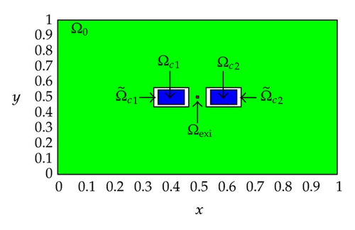
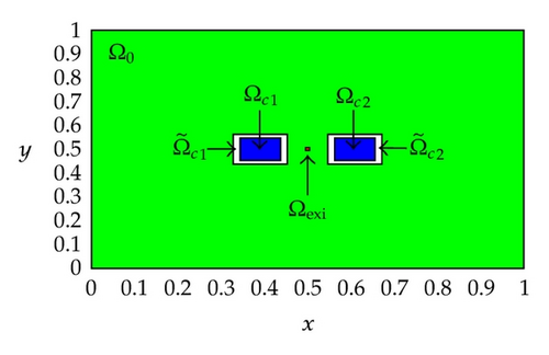
Also, observe that the control domain for Test Case 1 is close to the excitation domain while the control domain for Test Case 2 is a little bit far away from the excitation domain. These positions of the control domain are purposely set for studying the effects of the control domain position on the optimal control problem of monodomain model. In our numerical experiments, the control domain might corresponds to the electrodes of the implantable cardioverter defibrillator (ICD) implanted in the chest of patients who are at significant risk of sudden cardiac death. More specifically, we are trying to locate a better position for implanting the electrodes of the ICD to ensure a successful and efficient defibrillation.
| Parameter | Value | Units |
|---|---|---|
| β | 103 | cm−1 |
| Cm | 10−3 | mF cm−2 |
| 3 × 10⁻³ | S cm−1 | |
| 3.1525 × 10⁻⁴ | S cm−1 | |
| Vth | 1.3 × 101 | mV |
| Vp | 102 | mV |
| c1 | 1.5 | mS cm−2 |
| c2 | 4.4 | mS cm−2 |
| c3 | 1.2 × 10⁻² | ms−1 |
| c4 | 1 | Dimensionless |
| α | 10−4 | Dimensionless |
| λ | 7.062 × 10⁻¹ | Dimensionless |
| δ | 1 | Dimensionless |
| μ | 10−4 | Dimensionless |
| ρ | 10−1 | Dimensionless |
| Δt | 0.1 | ms |
| Δt1 | 2.5 × 10⁻² | ms |
| Δt2 | 10−3 | ms |
5.2. Experiment Results
The minimum values of the reduced cost functional and the corresponding norm of reduced gradient along the optimization process for Test Case 1 and Test Case 2 are depicted in Figure 2. As shown in the figures, Test Case 1 and Test Case 2 successfully converge to the optimal solution by taking 18 and 27 optimization iterations. Also, observe that the minimum value for Test Case 1 is lower than that one for Test Case 2. This result implies that when the control domain is relocated to a position which is far away from the excitation domain, more iteration is needed for the MDY method to converge to the optimal solution.
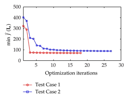
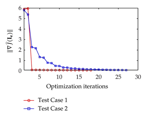
As illustrated in Figure 2, the reduced gradient for Test Case 1 decreased sharply at iteration 3, followed by a smooth decrease till the end of optimization iterations. On the other hand, the reduced gradient for Test Case 2 decreases less sharply than that of Test Case 1 at iteration 3 and slowly approaches zero with a smooth decrease.
Figure 3 illustrates the uncontrolled solutions for the optimal control problem of monodomain model at times 0.2 ms, 0.8 ms, 1.5 ms, and 2.0 ms. Notice that the uncontrolled solutions are obtained by setting the control variable equal to zero at the control domain as well as at the outside of the control domain, that is, Ie = 0 for x ∈ Ω. As shown in the figures, the excitation wavefront spreads from the excitation domain to the nearby computational domain during the time interval from 0 ms to 2 ms. This result implies that if no extracellular current (Ie) is applied to the control domain, the excitation wavefront will continue to spread to the entire computational domain.
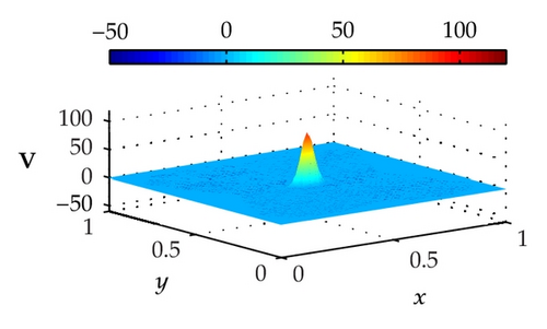
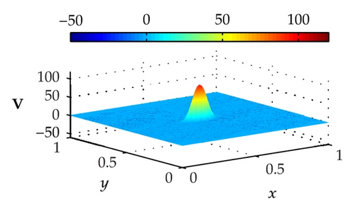
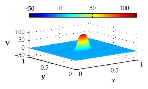
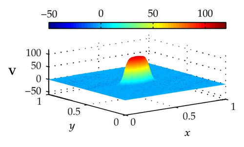
Figure 4 illustrates the optimally controlled solutions for Test Case 1 at times 0.2 ms, 0.8 ms, 1.5 ms, and 2.0 ms. As shown in the figures, the excitation wavefront is successfully dampened out by the optimal extracellular current . Note that the excitation wavefront is almost completely dampened out at time 1.5 ms. Next, Figure 5 depicts the optimally controlled solutions for Test Case 2 at times 0.2 ms, 0.8 ms, 1.5 ms, and 2.0 ms. Again, the excitation wavefront is successfully dampened out by . Observe that at time 1.5 ms, the excitation wavefront is still not completely dampened out. Thus, by comparison to Test Case 1, longer time is needed for Test Case 2 to dampen out the excitation wavefront.
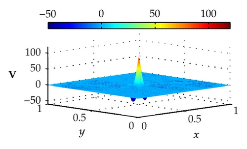
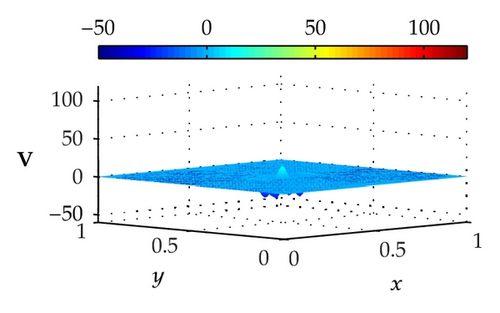
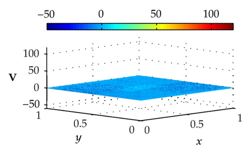
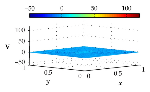
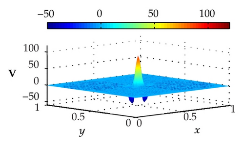
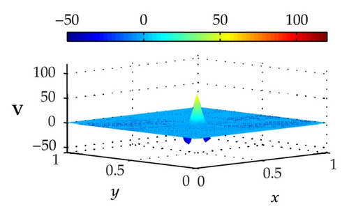
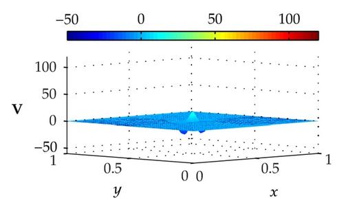
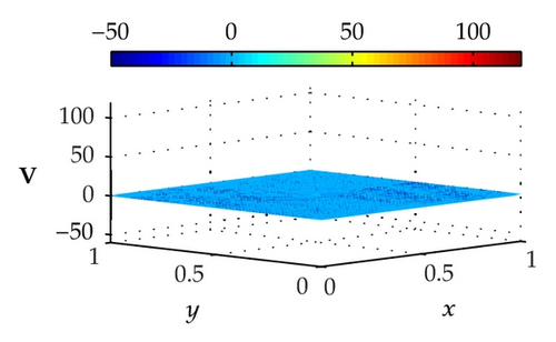
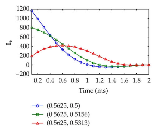
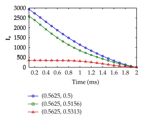
Figure 6 displays the optimal extracellular current at three fixed points, that is, (x1, y1) = (0.5625,0.5), (x2, y2) = (0.5625,0.5156), and (x3, y3) = (0.5625,0.5313) over the time evolution. As shown in the figures, the highest extracellular current required by Test Case 1 in the defibrillation process is around 1200 mA cm−3. On the other hand, the highest extracellular current required by Test Case 2 in the defibrillation process is twice as large as Test Case 1, that is, approximately 3000 mA cm−3. This result implies that higher extracellular current is necessary if the control domain is relocated to a position which is far away from the excitation domain.
6. Conclusions
This work studies the effects of the control domain position on the optimal control problem of cardiac arrhythmia by using two test cases. The control domain for Test Case 1 is close to the excitation domain, while the control domain for Test Case 2 is a bit further away from it. Our numerical results show that when the control domain is relocated to a position which is far from the excitation domain (as demonstrated by Test Case 2), more iteration is needed for the MDY method to converge to the optimal solution. Numerical results also show that longer time is needed by Test Case 2 for dampening out the excitation wavefront. Moreover, if the control domain is far from the excitation domain, higher extracellular current is required during the defibrillation process in order to dampen out the excitation wavefront. Thus, if we know which part of the heart of the patient is frequently suffering from cardiac arrhythmia, the electrodes of the implantable cardioverter defibrillator (ICD) should be implanted close to that part for improving the performance of the defibrillation process.
Acknowledgments
The work is financed by Zamalah Scholarship and Research University Grant (GUP) Vote 06J26 provided by Universiti Teknologi Malaysia and the Ministry of Higher Education of Malaysia.


