Direct Simulation of Low-Re Flow around a Square Cylinder by Numerical Manifold Method for Navier-Stokes Equations
Abstract
Numerical manifold method was applied to directly solve Navier-Stokes (N-S) equations for incompressible viscous flow in this paper, and numerical manifold schemes for N-S equations coupled velocity and pressure were derived based on Galerkin weighted residuals method as well. Mixed cover with linear polynomial function for velocity and constant function for pressure was employed in finite element cover system. As an application, mixed cover 4-node rectangular manifold element has been used to simulate the incompressible viscous flow around a square cylinder in a channel. Numerical tests illustrate that NMM is an effective and high-order accurate numerical method for incompressible viscous flow N-S equations.
1. Introduction
In computational fluid dynamics (CFD), Navier-Stokes (N-S) equations for incompressible viscous flow can be solved by several numerical methods generally, such as finite difference method (FDM), finite element method (FEM), and finite volume method (FVM) [1]. The applications of FDM are affected for unsuitability to complicated structure flow field and inconservation of field variables [2]. The FEM schemes for N-S equations are very complicated, and the computational efficiency of nonstandard FEMs is low [3]. FVM is an effective numerical method for solutions of fluid flow, but exact treatments of the moving boundary are difficult and complicated [4]. Furthermore, fractional step algorithms are used to solve velocity and pressure variables unintegratedly in all these numerical methods, and the continuity equation and momentums equations are satisfied, respectively [5]. All the defects of these numerical methods will affect the computational efficiency and accuracy.
Numerical manifold method (NMM) also known as manifold method or finite cover method (FCM) is a generalized numerical method proposed by Shi in the early 1990s [6, 7]. The method performs numerical computation with finite element cover system, which is composed of two independent cover grids: mathematical cover grid and physical cover grid. Mathematical covers define the accuracy of approximate solution, and physical covers determine the solution domain. High accurate numerical manifold schemes for mathematical physics equations can be constructed by adopting different cover functions and cover-weighted functions for physical variables in finite element cover system [8]. The method has been successfully applied in some complicated engineering problems, such as numerical simulation of crack initiation and propagation, damage evolvement of fractured rock masses, coupling vibration, and potential flow problem, and the advantages have been demonstrated in these fields [9–12]. As to fluid flow problems, direct-numerical-solution coupled velocity and pressure variables can be implemented by adopting manifold schemes with mixed cover for N-S equations. The authors have applied numerical manifold method into analyses of unsteady incompressible viscous flow, and the results have illustrated the validity of NMM [13].
Flow around a square cylinder is a typical model to validate the performance of numerical methods for solution of incompressible viscous N-S equations. The flow structure has been investigated experimentally and numerically. Experimental investigations have shown that the flow characteristic is different at different Reynolds numbers [14]. FVM, FDM, and others numerical methods have been applied to simulate the flow around a square cylinder, the detail results have been obtained and met the experimental results [15–17]. The experimental and numerical results have been employed to validate the numerical methods in CFD as benchmarks.
In this paper, numerical manifold schemes of direct solutions coupled velocity and pressure for N-S equations were constructed and applied to analyze incompressible viscous flow around a square cylinder in a parallel channel. The validations of numerical schemes to steady and unsteady flow were completed.
2. Numerical Manifold Schemes for N-S Equations of Incompressible Viscous Flow
2.1. Galerkin Integration Expressions of N-S Equations
2.2. Numerical Manifold Schemes for N-S Equations
2.2.1. Element Velocity and Pressure Cover Functions
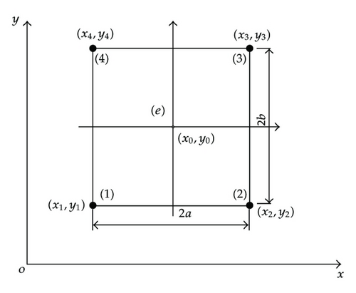
2.2.2. Element Manifold Schemes
Equations (2.8a) and (2.8b) are the nonlinear algebra equations with respect to coupled velocity and pressure DOF variables and first-order linear ordinary differential equations with respect to time.
3. Some Key Techniques
3.1. Mixed Cover Functions for Velocity and Pressure
In FEM, when velocity and pressure field are discretized in the same way, the discrete element can not be ensured to satisfy the Ladyzanskya Babuska Brezzi stability condition (LBB condition), and these kinds of element cannot be applied to directly solve N-S equations coupled velocity and pressure for the spatial oscillation of pressure field. Mixed elements can be built to meet the LBB condition by increasing velocity interpolation node [18], but the elements are inconvenient to apply in practice for the complicated calculation process and difficult element discretization.
In finite element cover system of NMM, the element cover functions are composed of the weight functions and the cover functions of physical covers. Generally, the weight functions will adopt the element shape functions as in FEM, which are usually defined by the element shape and nodes. The cover functions of every physical cover for different physical variables can employ different order functions according to the solving physical equations. When NMM is applied to solve N-S equations for incompressible viscous flow, the velocity and pressure field can be discretized in the same way and the weight functions will employ the same interpolation functions for element velocity and pressure variables. But, the cover functions of every element physical cover can apply different order functions for velocity and pressure variables, so it will form a manifold element with mixed cover functions for velocity and pressure variables, which can meet the requirements of different order approximate functions for velocity and pressure in Galerkin integration expressions (2.1a) and (2.1b) and satisfy the LBB condition for increasing the DOF numbers of velocity variables. The mixed cover manifold elements can be applied in direct solution of incompressible viscous N-S-equations-coupled velocity and pressure variables.
3.2. Solution of Manifold Equations for Steady N-S Equations
The manifold equations (3.3a) and (3.3b) are nonlinear algebra equations and can be solved by two methods of directly linearizing alternate iteration and Newton-Raphson iterative in general.
3.3. Solution of Manifold Equations for Steady N-S Equations
The manifold equations (3.7) for unsteady flow can be solved by iterative methods. In this paper, Newton-Raphson iterative method is also used here for solution of unsteady flow manifold equations.
4. Numerical Example of Flow around a Square Cylinder in a Channel
4.1. Analysis for Steady Flow past a Step
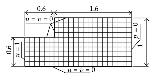
In numerical analysis of flow past a step, finite element cover system and boundary conditions are shown in Figure 2(a), the characteristic velocity of the flow field inlet is u = 1 and v = 0, the fluid density is ρ = 1, and three dynamic viscosities of fluid are μ = 0.01, 0.005, 0.0025, and so Re numbers are known as Re=100, 200, 400, respectively. All the flow field is meshed into 196 elements and 229 nodes by 0.1 × 0.1 rectangular grids.
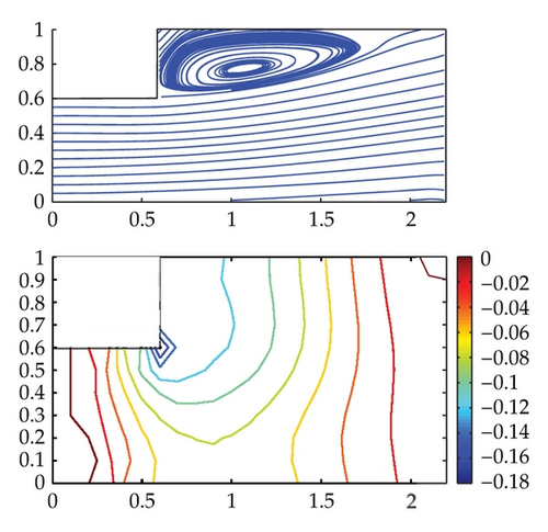
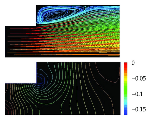
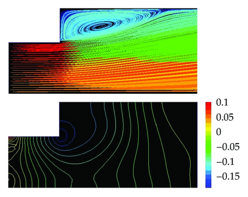
The streamline and pressure distribution in flow field past a step at Re = 200 are shown in Figure 2(b). The streamline patterns obtained from direct numerical solutions have revealed the vortex structure at the step of flow field, and high accurate pressure distributions have been obtained as well. The numerical solutions from FVM are shown in Figures 2(c) and 2(d) comparatively, which obtained from 0.1 × 0.1 and 0.05 × 0.05 rectangular grids, respectively. The NMM results from 0.1 × 0.1 grids are nearly coincident with the FVM results from 0.05 × 0.05 grids. The comparative analyses illustrate that numerical manifold schemes with mixed cover are stable numerical schemes for incompressible viscous flow, can implement direct numerical solution of N-S equations coupled velocity and pressure variables and can improve the solution accuracy at the same grids compared with FVM.
4.2. Analysis for Steady Flow around a Square Cylinder in a Channel
The flow field configuration and boundary conditions of flow around a square cylinder in a channel are shown in Figure 3. The length of the channel is L = 4, the width is W = 1. The size of square cylinder is d × d = 0.25 × 0.25, its horizontal axis coincides with the channel’s centerline, and its vertical axis is perpendicular to the channel’s centreline. The velocity condition of the inlet AD is is the average flow velocity in the channel, ym = 0.5 is the channel centerline) and v = 0, the pressure condition of outlet BC is p = 0, and the nonslip boundary conditions are set on other fixed walls, that is, u = v = 0.
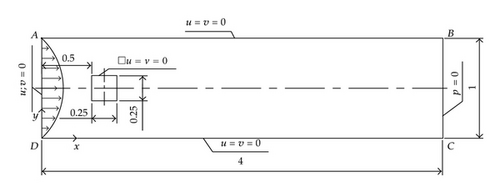
The flow field is meshed by three mixed grids, one is that 32 × 16 uniform element grid is used for the domain from x = 0 to x = 2 and 20 × 16 element grid for the domain from x = 2 to x = 4, the entire flow field is meshed by 52 × 16 = 832 elements and 53 × 17 = 901 nodes; the second one is that 64 × 32 uniform element grid is used for x = 0 ~ 2 and 40 × 32 element grid for x = 2 ~ 4, the flow field is meshed by 104 × 32 = 3328 elements and 105 × 33 = 3465 nodes; the third one is that 96 × 48 uniform element grid is used for x = 0 ~ 2 and 64 × 48 element grid for x = 2 ~ 4, the flow field is meshed by 160 × 48 = 7680 elements and 161 × 49 = 7889 nodes.
The numerical analyses of steady flow at different Re numbers (Re = 25, 50, 75, 100, 150) are performed by the NMM solutions of steady N-S equations. The streamline patterns and variables distributions of flow field at Re = 100 from three different element grids are compared. The results from the first element grid are different to these from two other grids, but the results from the second grid are closely similar to these from the third one, and the average difference of velocity and pressure on the channel centreline is less than 5%, so the second element grid is enough for flow at Re < 100, and the third element grid or finer element grid is more reasonable for flow at Re = 100 and 150.
The streamline patterns and pressure distributions at different Re numbers are shown in Figure 4. At Re = 25 and 50, there are two stable symmetrical vortexes behind the square cylinder, and the flow patterns are similar to the numerical solutions of Mukhopadhyay et al. [15]. As Re number increases to Re ≈ [50, 200], Cherry’s results show that two vortexes become unsymmetrical and Karman vortex street is formed behind the square cylinder gradually [14], but the stable convergent results are obtained from NMM solutions of steady N-S equations at Re = 75, 100, and 150, and there are also two stable symmetrical vortexes behind the square cylinder. The distances from back flow point of the vortexes to square cylinder at Re = 25, 50, 75, 100, 150 are 1.0, 1.2, 1.4, 1.6, 1.8, respectively, which are approximately linear with Re numbers. These results illustrate that numerical manifold schemes for steady N-S equations have the strong-stability-preserving property.
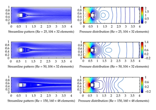
In NMM analysis unlike FVM and FEM analysis, the pressure distributions of flow field are obtained from direct numerical solutions of N-S equations and continuity equation, so it can improve the solution accuracy of pressure field. The pressure distributions of flow field show that high-pressure area is formed in frontage of the square cylinder for flow blockage, low pressure areas are formed near behind two front corner points for flow separating, and large pressure gradient is produced near the corner points. The pressure distributions are symmetrical, and the pressure of flow field will decrease as Re number increasing.
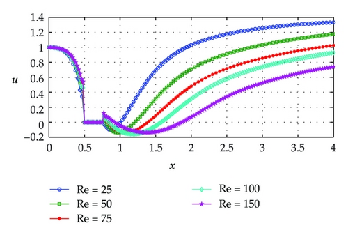
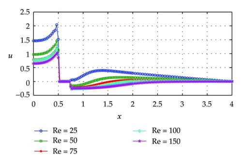
The velocity u distributions along horizontal lines through geometric center of flow field are shown in Figure 5. The velocity u drops rapidly from inlet to the square cylinder for flow blockage. Negative velocity appears behind the cylinder for back flow, and the velocity will rise gradually with away from the cylinder, and the velocity restoring becomes slow as Re number increases. The pressure distributions along horizontal lines through geometric center of flow field are shown in Figure 6. The pressure rises gradually from inlet to the square cylinder. Positive pressure appears behind the cylinder at low Re number, negative pressure appears at comparatively high Re number, and the pressure will drops or rises to zero at outlet of flow field.
4.3. Analysis for Unsteady Flow around a Square Cylinder in a Channel
The flow field configuration and boundary conditions of unsteady flow around a square cylinder in a channel are the same as these of steady flow, and the flow field is meshed by the third mixed grids. The unsteady flows at different Re numbers (Re = 50, 75, 100, 150) are also analyzed through NMM solutions of N-S equations in this paper, where numerical solutions for steady flow at Re = 50 are adopted as the initial conditions, the total computational time is 10 s, and the time step is 0.01 s.
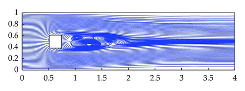
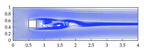
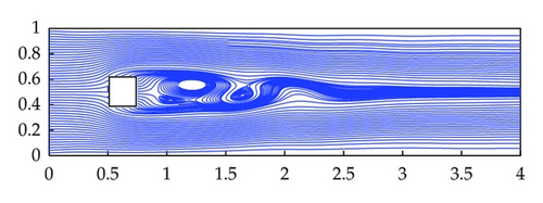
When Re ≤ 50, numerical solutions from unsteady flow analyses are closely similar to the results from steady flow analyses, and there are two steady symmetrical vortexes behind the square cylinder. As Re number increasing, two vortexes become unsymmetrical, and Karman Vortex Street is formed behind the square cylinder gradually. The streamline patterns for flow field at Re = 150 are shown in Figure 7, and the periodical change process of appearing, developing, moving, separating of the vortexes are clearly displayed in the streamline patterns. The Strouhal number is 0.2438, the difference is 2.2% and 6.5% to [15, 16]. The flow patterns are similar to Mukhopadhyay’s and Yutaka’s results, which is obtained from very fine element grid [15, 17].
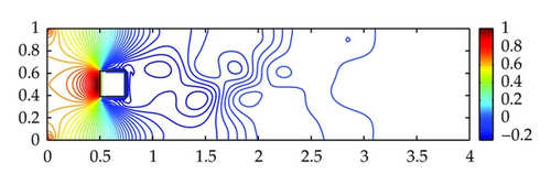
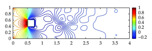
The pressure contours for flow field at Re = 150 are show in Figure 8. The pressure distributions beside and in frontage of the square cylinder are almost identical to the results from steady flow analyses and are different behind the cylinder, which will change with the moving of vortexes.

5. Summary
Numerical manifold method for direct coupled solution of incompressible viscous flow N-S equations has been developed in this paper. Numerical manifold schemes integrated velocity and pressure were derived based on Galerkin-weighted residuals method as well. Mixed cover with linear polynomial function for velocity and constant function for pressure was adopted in finite element cover system. Compared with FVM and FEM, in NMM for incompressible viscous flow, the accuracy of velocity variables approximation can be improved by adopting high-order cover function, direct numerical solution of N-S equations, and continuity equation coupled velocity and pressure variables can be implemented by adopting finite cover system with mixed cover manifold element, so it can improve the solution accuracy of velocity and pressure variables.
As an application, mixed cover 4-node rectangular manifold element has been used to simulate flow around a square cylinder in a channel and past a step at low Re numbers. As to flow around a square cylinder in a channel, accurate numerical results have been presented for steady flow at Re = 25, 50, 75, 100, 150 and for unsteady flow at Re = 100, 150. The rules on streamline patterns and pressure distributions were analyzed in details. Numerical solutions were in very good agreement with the published data from very fine element meshes. Numerical tests indicate that manifold method is an effective and high-order accurate numerical method for incompressible viscous flow Navier-Stokes equations.
Acknowledgment
Financial support for this project was provided by the National Natural Science Foundation of China (no. 50975050).


