Efficient Fatigue Analysis of Helix Elements in Umbilicals and Flexible Risers: Theory and Applications
Abstract
Fatigue analysis of structural components such as helix tensile armors and steel tubes is a critical design issue for dynamic umbilicals and flexible pipes. The basis for assessment of fatigue damage of such elements is the long-term stress cycle distribution at critical locations on the helix elements caused by long-term environmental loading on the system. The long-term stress cycle distribution will hence require global dynamic time domain analysis followed by a detailed cross-sectional analysis in a large number of irregular sea states. An overall computational consistent and efficient fatigue analysis scheme is outlined with due regard of the cross-sectional analysis technique required for fatigue stress calculation with particular attention to the helix elements. The global cross-section is exposed to pure bending, tensile, torsion, and pressure loading. The state of the different cross-section elements is based on the global response. Special emphasis is placed on assessment of friction stresses caused by the stick-slip behavior of helix elements in bending that are of special importance for fatigue life assessments. The described cross-sectional analysis techniques are based on an extensive literature survey and are hence considered to represent industry consensus. The performance of the described calculation scheme is illustrated by case studies.
1. Introduction
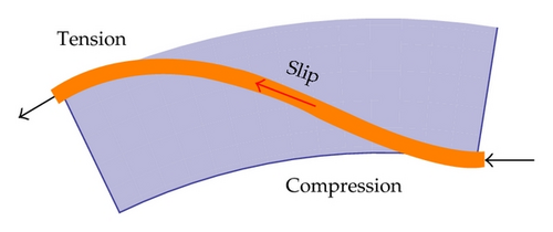
The required bending flexibility of risers and umbilicals is achieved by arranging strength and functional elements in a helix geometry. The helix geometry allows the elements to slip in order to release axial stresses built up by cross-sectional bending. This mechanism is essential for arranging flexible risers and umbilicals in compliant configurations that are capable of absorbing loads due to floater motions in harsh environmental conditions. The penalty is, however, that assessment of fatigue stresses in helix elements becomes complex due to the stick-slip behavior of helix elements in bending, as in Figure 1. The purpose of fatigue analysis is assessment of fatigue damage in all relevant elements in the cross-section for a long-term dynamic loading environment. Fatigue analysis of helix elements such as tensile armors and steel tubes is a critical design issue for umbilicals and flexible pipes. Critical areas are normally at the floater interface where bend limiting devices, that is, a bend stiffener or a bellmouth, are applied to avoid overbending in extreme load situations and reduce long-term fatigue loading, see, for example, [1, 2] for further details.
- (1)
Wave-induced fatigue loading due to direct wave loading and associated floater motions;
- (2)
Vortex-induced vibration (VIV) in steady current conditions.
Both loading scenarios will require fatigue damage calculations in numerous short-term conditions to represent the long-term fatigue loading environment. As an example, wave-induced fatigue analyses will typically require stress calculation in about 100–300 stationary irregular sea states each with duration of 1 hour. In addition, an iterative analysis scheme is in general required for consistent assessment of fatigue damage caused by VIV due to the highly nonlinear stick-slip damping mechanism in bending, see [4] for details.
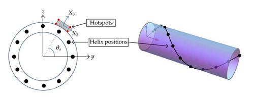
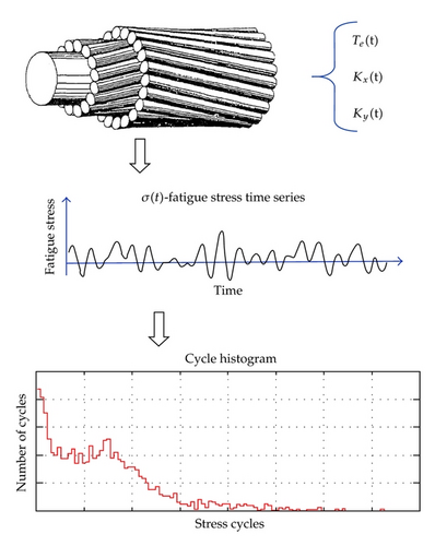
The basis for assessment of fatigue damage in helix elements is the long-term cycle distribution in several hot-spots, that is, critical positions on the helix cross-section, for a representative number of helix positions, that is, positions along the helix in one pitch, as shown in Figure 2.
- (i)
applicable to umbilicals, power cables, flexible risers, and similar unbonded structures;
- (ii)
load sharing analysis for combined loading;
- (iii)
calculation of cross-sectional stiffness properties: axial, bending, and torsion;
- (iv)
fatigue stress analysis of helix elements considering stick-slip behavior in bending;
- (v)
Calculation of consistent fatigue stresses by direct application of global response time series as external loading.
- (vi)
calculation of capacity curves for the entire cross-section in compliance with applicable design codes;
- (vii)
short-term fatigue life and long-term fatigue analysis capabilities;
- (viii)
efficient and robust analysis scheme;
- (ix)
well-documented transparent theoretical formulation representing industry consensus;
One of the main drivers behind this development has been to establish an efficient and consistent fatigue analysis scheme. The main focus of this paper is to give a detailed description of the cross-sectional response models applied to achieve an efficient and robust analysis scheme.
2. Numerical Model
2.1. Introduction
The computational model is based on an essential 2D formulation allowing for cross-sectional modeling of composite tubes containing helix elements in an unbonded structure. 2D is here to be understood as an average description where the averaging is applied in longitudinal pipe direction. The consequence of this is that possible 3D effects close to terminations can not be handled.
The helix elements are assumed to be arranged in well-defined layers allowing for treating each helix layer by means of an equivalent tube model with stiffness properties assembled from the individual helix elements. Different types of helix elements may be applied in the same layer to model, for example, umbilicals. Different distance from the cross-sectional centerline may also be specified for the individual elements in the same layer. All elements are assumed to have linear elastic material properties.
2.2. Response Models
- (i)
axis-symmetric loads due to effective tension, torsion moment, and internal and external pressure;
- (ii)
pure bending, that is, constant global cross-section curvature.
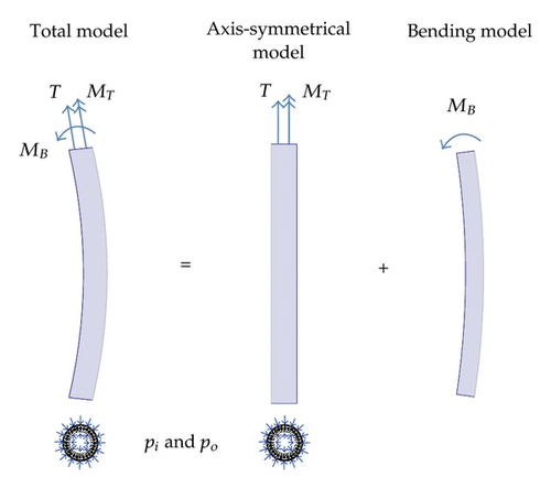
Separate response models are established for the different load conditions in order to obtain an overall robust, flexible, and computational efficient numerical solution scheme. The main purpose and underlying assumptions for these response models are discussed in the following. The purpose of the axis-symmetric response model is to establish the load sharing between the individual components of the cross-section as well as contact forces between the layers under axis-symmetric loading: effective tension, torsion, and hydrostatic pressure loads. This analysis requires a full model of the cross-section and needs to solve the overall static equilibrium with due regard to interlayer contact. Frictional effects are disregarded in the axis-symmetrical response model.
Effective tension is used to comply with other software used in this industry segment, like Riflex [7]. The use of effective tension is outlined in Sparks [8].
- (i)
constant interlayer contact pressure found by axis-symmetrical analysis. Additional contact pressure induced by bending itself is neglected;
- (ii)
friction/contact between helical elements in the same layer is neglected, for example, possible blocking/locking interlayer behavior can not be modeled explicitly;
- (iii)
no end effects included, that is, bending takes place well away from terminations;
- (iv)
constant global cross-sectional curvature is assumed;
- (v)
axial slip of helix elements is assumed, that is, loxodromic helix geometry assumed during bending.
2.3. Axis-Symmetrical Response Model
2.3.1. General
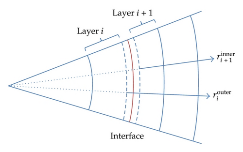
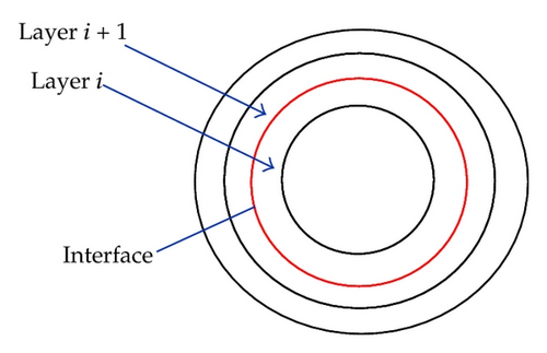
The axis-symmetrical model is built up of concentric layers to model the entire cross-sections. All layers are assumed to have the same axial and torsional deformation, while the radial deformation is described separately for all layers. Each layer will hence have 1 or 2 radial degrees of freedom (dof) depending on whether the radial deformation of the layer itself is considered or not. The element types used in modeling and analysis are listed in Table 1.
| Element type | Assumption |
|---|---|
| Thin cylindrical element | Constant through thickness radial displacements; axial, circumferential, and in-plane shear strains: εxx, εθθ, and εxθ. |
| Thick cylindrical element | Logarithmic through thickness radial displacements; radial, axial, circumferential, and in-plane shear strains: εRR, εxx, εθθ, and εxθ. |
| Core element | Generalized cylinder element where the effect is expressed through and element stiffness matrix: kij. |
| Helix element | Helix element with axial strains only: ε011. |
| Helix element | Helix element with axial strains, curvatures, and torsional shear strains: ε011, κ2, κ3, and γs. |
The cylinder layers are intended for modeling of concentric plastic/metallic sheaths, for example, inner/outer pressure barrier of flexible pipes and external/interior sheaths of umbilicals. The core element is intended for modeling of resulting stiffness properties of one or several layers. A typical application is modeling of resulting stiffness properties of underlying layers supporting one or several layers of cross-wound tensile amours. The helix layers are modeled as equivalent thin cylinder layers in the axis-symmetrical analysis. The equivalent cylinder layer is established by assembling the stiffness contributions from each helix component in the layer. The stiffness matrix of each helix element is derived based on slender beam theory assuming the as-produced nominal helix geometry as initial stress-free condition, that is, a state of no stress. The deformations and stresses of each helix component due to axis-symmetrical loading are hence uniquely described by the global axial, torsional, and radial deformation of each layer. Full details of all elements are given in Skeie [5] while the kinematics of the cylindrical and helix element are pursued next.
2.3.2. Kinematics
2.3.3. Governing Equations
| Feature | Test [11] | Vaz et al. [11] | Sævik and Bruaseth [12] | Skeie [5] |
|---|---|---|---|---|
| EA under tension, (MN) | 70–101 | 82.9 | 100 | 79.5 |
| Coupling—tension/torsion (m) | 0.19 | 0.21 | 0.19 | |
| GJ clockwise, T = 0 kN(kNm2) | 14.5–56.0 | 44.7 | 44.3 | 45.4 |
| Coupling clockwise—torsion/tension, (rad/m) | 182 | 188 | 180 | |
| GJ anticlockwise, T = 0 kN(kNm2) | 15.9–17.2 | 19.1 | 19.5 | 18.7 |
| Coupling anticlockwise—torsion/tension, (rad/m) | −406 | −330 | −343 |
2.4. Bending Model
2.4.1. General
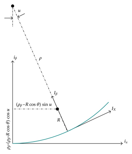
The additional stresses due to bending can be derived by assuming that the helix follows a loxodromic curve during cross-sectional bending. This means that the helix remains in its original position on the supporting cylinder surface during bending, and that it slips in axial direction. This geometrical assumption has gained consensus in the literature, see, for example, [13–15]. Experiments have also been conducted to validate this assumption, see, for example, [16]. Based on this geometrical assumption, it is fairly straightforward to establish the stress components during bending, see, for example, [13, 14]. Full details are given in [5].
- (i)
local bending stress due to bending about local weak/strong axes of the helix,
- (ii)
friction stress due to the stick/slip behavior in bending.
It is noted that other models for bending exist and especially the path followed by the helix when it slips, a loxodromic or the geodesic path. The subject is pursued in a number of publications, and discussions may be found in Féret and Bournazel [17], Out and von Morgan [18], Kraincanic and Kebadze [14], and Østergaard et al. [19] among others.
2.4.2. Kinematics
2.4.3. Stick-Slip Behavior

- (i)
Extend formulations given in 1st quarter pitch to arbitrary helix positions.
- (ii)
Implementation of stick—slip stress hysteresis formulation.
- (iii)
Extend formulas given for bending about β′-axis to bi-axial bending.
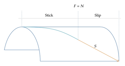
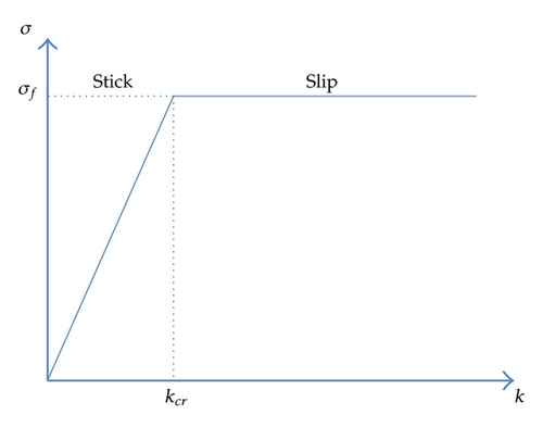
This generalization is fairly straight forward but somewhat detailed. A detailed description is therefore not given, but it suffice to note that the approach is based on the definition of proper sign convention, symmetry observations and proper bookkeeping of curvature reversals.
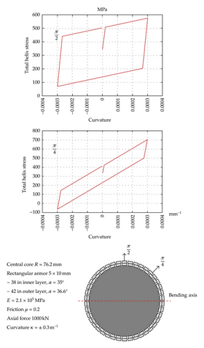
An example of the performance of the bending hysteresis model for tensile armor stresses is displayed in the Figure 10 for a harmonic curvature loading history. A significant variation in the effect from friction stress for different helix positions is observed. This underlines the importance of consistent treatment of friction stresses due to bi-axial bending in fatigue analysis of helix elements.
3. Case Studies
3.1. Capacity Curves
- (1)
establish capacity curve and resulting stiffness properties of the composite helix component. This is done by a separate straightforward cross-sectional analysis using a cross-sectional model of the composite helix component only;
- (2)
include composite helix component in the total cross-sectional model in terms of equivalent stiffness—geometrical parameters established from (1). Load sharing analysis yields tension as well as local curvature acting on the composite helix component. Utilization in the composite helix component is then based on the capacity curve from (1).
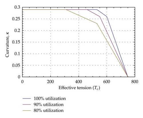
Several levels of recursive calculation can be applied to establish consistent capacity curves of complex cross-sectional layouts. The main benefit of the recursive calculation scheme is that very complex cross-sections can be subdivided into simpler components that can be solved by standard cross-section analysis without having to build a comprehensive overall cross-sectional model.
3.2. Fatigue Analysis
3.2.1. System Description
Fatigue analysis of rectangular cross-wound tensile armors of an umbilical operated from a turret-moored FPSO in typical Norwegian environmental conditions is considered [20]. The umbilical is arranged in a classic wave configuration with bend stiffener interface to the floater, see Figure 12. The fatigue loading environment is described by the omnidirectional wave scatter diagram.

3.2.2. Analysis Methodology
- (i)
discretization of the wave scatter diagram into representative number of blocks. Each block covers several sea states in the wave scatter diagram. 30 blocks are used in the present study to represent the long-term fatigue loading;
- (ii)
perform global response analyses for all blocks in the wave scatter diagram considering all heading and direction combinations as defined in Table 3. A total of 270 short-term global response analyses is hence required to describe the long-term fatigue loading on the system;
- (iii)
perform helix fatigue analysis for all fatigue loading conditions using simultaneous time histories of biaxial curvature and effective tension from the global analysis as input.
| Vessel heading (deg) | Direction | Probability of vessel heading per direction |
|---|---|---|
| 0 | Near | 60% |
| 15 | Near | 30% |
| 30 | Near | 10% |
| 0 | Far | 60% |
| 15 | Far | 30% |
| 30 | Far | 10% |
| 0 | Cross | 60% |
| 15 | Cross | 30% |
| 30 | Cross | 10% |
The methodology as outlined in [21] is used as basis for the wave scatter diagram discretization to achieve fatigue life estimates with adequate statistical confidence.
- (i)
establish fatigue stress time histories at all locations/hotspots. This analysis is performed by combined axis-symmetrical analysis and bending analysis at each time step. In this way, the interlayer contact forces governing the stick-slip bending response are updated according to the instantaneous effective tension loading;
- (ii)
establish cycle histogram by rain flow counting of the generated fatigue stress time.
- (i)
accumulate long-term cycle histograms at all locations/hotspots with due consideration of the probability of occurrence of the short-term fatigue loading conditions;
- (ii)
establish fatigue life from the long-term cycle histograms.
Key figures for the helix fatigue analysis are summarized in Table 4. The key figures for the global analyses and subsequent fatigue analyses show that the computational efforts required are substantial. It should be emphasized that this example is of representative size for this type of analysis.
| Number of hot-spots (corner points) | 4 |
| Number of helix locations | 12 |
| Total number of fatigue stress time series calculations of 1-hour duration (270 × 76 × 4 × 12) | 984960 |
3.2.3. Evaluation of Results and Numerical Performance
- (i)
helix model with stick-slip modeling included;
- (ii)
helix model with no friction.
- (i)
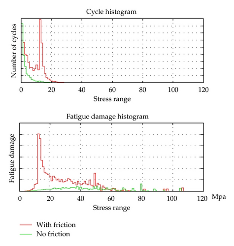
a pronounced peak in the cycle histogram is observed at 15 MPa. This corresponds to the maximum friction stress range;
- (ii)
the effect from frictional stresses is decisive for fatigue life prediction. Consistent treatment of the stick-slip behavior in bending is hence essential;
- (iii)
a substantial part of the fatigue damage can be attributed to the upper part of the stress cycle histogram, that is, to relatively few large stress cycles. It is therefore essential that the duration of the short-term simulations is sufficient to give a representative frequency of large stress cycles.
The total computation time for the helix fatigue analysis on a standard single core lap top is about 5 hours. The computation time is highly acceptable considering the size of the problem. Parallel computing functionality is included in the software; thus, the computation time may be reduced proportional to the number of available processors. No numerical instabilities or anomalies were detected.
4. Conclusions
An overall computational consistent and highly efficient helix fatigue analysis scheme has been established. This has been achieved by combined use of a versatile and efficient axis-symmetrical solver with an analytical helix bending model. This model ensures full consistency with the global response model as the computational efficiency allows for application of global response time histories as direct loading on the cross-sectional response model. The effect from frictional stresses is decisive for fatigue life prediction. Consistent treatment of the stick-slip behavior in bending is hence essential for fatigue life prediction on nonbonded cross-sections containing helix elements.


