Generalized Projective Synchronization between Two Different Neural Networks with Mixed Time Delays
Abstract
The generalized projective synchronization (GPS) between two different neural networks with nonlinear coupling and mixed time delays is considered. Several kinds of nonlinear feedback controllers are designed to achieve GPS between two different such neural networks. Some results for GPS of these neural networks are proved theoretically by using the Lyapunov stability theory and the LaSalle invariance principle. Moreover, by comparison, we determine an optimal nonlinear controller from several ones and provide an adaptive update law for it. Computer simulations are provided to show the effectiveness and feasibility of the proposed methods.
1. Introduction
Over the past two decades, the investigation on the synchronization of complex networks has attracted a great deal of attention due to its potential applications in various fields, such as physics, mathematics, secure communication, engineering, automatic control, biology, and sociology [1–9]. In the literature, there are many widely studied synchronization patterns, which define the correlated in-time behaviors among the nodes in a dynamical network, for example, complete synchronization [10–12], lag synchronization [13–15], anti-synchronization [16–18], phase synchronization [19–21], projective synchronization [22–32], and so on. Projective synchronization reflects a kind of proportionality between the synchronized states, so it is an interesting research topic and has many applications. For instance, if this proportional feature is applied to M-nary digital communication, the communication speed can be accelerated substantially. In view of this merit, many researchers throw themselves into generalized projective synchronization.
Recent years have witnessed many written achievements on projective synchronization between two identical complex dynamical networks [22–30]. We introduce three typical references here. In [28], Chen et al. studied projective synchronization of time-delayed chaotic systems in a driven-response complex network, where the nodes are not partially linear and the scale factors are different from each other. In [29], Feng et al. investigated projective-anticipating and projective-lag synchronization on complex dynamical networks composed of a large number of interconnected components, in which the dynamics of the nodes of the complex networks were time-delayed chaotic systems without the limitation of the partial linearity. In [30], Wang et al. explored the problem of outer synchronization between two complex networks with the same topological structure and time-varying coupling delay with a new mixed outer synchronization behavior. In addition, a novel nonfragile linear state feedback controller is designed to realize the mixed outer synchronization between two networks and proved analytically by using the Lyapunov-Krasovskii stability theory.
However, in real world, studying the phenomena of synchronizing two different complex networks is closer to reality. The so-called different implies that the drive and response networks have different node dynamics, different number of nodes, or different topological structures. Recently, some related works have come out, such as [31, 32]. In [31], Zheng et al. probed into adaptive projective synchronization between two complex networks with different topological structures, although its systems contained time-varying delays. Some results on topology identification were obtained which can be also seen as a highlight of this paper. In [32], the generalized projective synchronization with the above three differences was investigated based on the LaSalle invariance principle. However, the model of complex network only has linear coupling and coupling time delay.
Due to the finite information transmission and processing speeds among the units, the connection delays in realistic modeling of many large networks with communication must be taken into account. Therefore, it is important to study the effect of time delay in synchronization of coupled systems. Usually, time delay involves two parts. One is the delay inside the systems, called internal delay. The other is caused by the exchange of information between systems referred to as coupling delay. Moreover, nonlinear functions can display more nature phenomena. Hence, the internal delay and nonlinear functions are introduced into the considered neural networks in this writing. What is more, the nonlinear functions in the drive and response networks are also different. In particular, three comparable nonlinear controllers are presented to realize the GPS based on the LaSalle invariance principle and some basic inequalities. On the contrary, an optimal nonlinear controller is produced eventually. In the last theorem, we use an adaptive control technique for the optimal nonlinear controller in order to make the feedback control gain small enough.
Notation. Throughout this paper, Rn and Rm×n denote n-dimensional Euclidean space and the set of m × n real matrices, respectively. λmin (A) represents the smallest eigenvalue of a symmetric matrix A. ⊗ is the Kronecker product. The superscript T of xT or AT denotes the transpose of the vector x ∈ Rn or the matrix A ∈ Rm×n. In is identity matrix with n nodes.
2. Model Description and Preliminaries
Now, two mathematical definitions for the generalized projective synchronization are introduced as follows.
Definition 2.1. If there is a nonzero constant σ such that
Definition 2.2. A continuous function f(·) : R → R is said to be the nonnegative-bound function class, denoted as f ∈ NBF(ξ), if there exists a positive scalar ξ, such that
The following hypothesis is used throughout the paper.
Assumption 2.3. For activation functions , there exist positive constants θi, βi, μi, γi, πi, δi (i ∈ {1,2, …, n}), such that , , , .
For better convenience, we denote that
Lemma 2.4 (see [33].)For a matrix B = (bij) ∈ Rp×q, denote α(B) = (1/2)max [p, q]max i,j |bij|, then
3. GPS between Two Different Neural Networks with Mixed Time Delays
In this section, we will make a study of GPS between two different neural networks with mixed time delays by means of the LaSalle invariance principle; the, Lyapunov direct method, and nonlinear feedback control technique.
Theorem 3.1. Suppose Assumption 2.3 holds; if the nonlinear controllers are chosen as follows:
Proof. Consider the Lyapunov functional candidate
Similarly, we can obtain the following four inequalities:
Substituting (3.6)–(3.13) into (3.5), we can obtain
Taking account of condition (3.3), we have .
Clearly, S = {ei(t) = 0, ki = k, i ∈ ℐ2} is the largest invariant set contained in . In terms of the LaSalle invariant principle, the trajectory asymptotically converges to the largest invariant set S with any initial value of (3.1), namely, lim t→+∞ ∥ei(t)∥ = 0, i ∈ ℐ2. Hence, the GPS between neural networks (2.1) and (2.2) is realized. The proof is completed.
In Theorem 3.1, the generalized projective synchronization of two different neural networks with time delay has been investigated by choosing suitable nonlinear feedback controllers. However, it requires feedback control gains to be large in ui given by (3.2), which is not practical. Hence, it is desirable to improve the scheme for reducing the feedback control gains to be as small as possible. Now, we give the following improvement scheme.
Theorem 3.2. Suppose Assumption 2.3 holds; if the nonlinear controllers are chosen as follows:
Proof. Select the following Lyapunov functional candidate:
Substituting (3.6), (3.7), (3.10), and (3.11) into (3.18), we can obtain
Remark 3.3. Comparing the infimum of the feedback control gain k in Theorem 3.2 with that in Theorem 3.1 implies that kres = −λmin (C1)+α(A1)(|σ | + θ2/|σ|)+α(B1) | σ | + α(G ⊗ Γ1)(|σ | + π2/|σ|)+α(Gτ ⊗ Γ2) | σ | + α(B1)μ2/|σ| + α(Gτ ⊗ Γ2)π2/|σ| is the extra part compared with the needed feedback gain in Theorem 3.2. Usually, it can be considered that kres > 0, which will be demonstrated in simulation.
Furthermore, in order to obtain much smaller feedback control gains, we choose more suitable controllers as follows.
Theorem 3.4. Suppose Assumption 2.3 holds. Under the nonlinear controllers
Proof. Choose the same Lyapunov functional as (3.17) in the proof of Theorem 3.2, and then we can get
Combining (3.6), (3.7), (3.10), (3.11), and (3.22), we could change inequality (3.19) into
Remark 3.5. It is easy to find that the infimum of k in (3.21) has one more term −λmin (C1) than (3.16). Because C1 is diagonally positive definite, −λmin (C1) < 0 demonstrates the required k in Theorem 3.4 is smaller than the one in Theorem 3.2.
If the two neural networks (2.1) and (2.2) have identical number of nodes, node dynamics, and topological structure, that is, N1 = N2, C1 = C2, A1 = A2, B1 = B2, f1 = f2, g1 = g2, Gij = Hij, , and Γ1 = Γ2, the error system (3.1) can be rewritten as follows:
Thus, we can obtain the following corollary for synchronizing the error system (3.24).
Corollary 3.6. Suppose the two neural networks (2.1) and (2.2) have identical number of nodes, node dynamics, and topological structure. If the following nonlinear controllers:
Proof. We construct the Lyapunov function as follows:
Furthermore, let us assume that system (3.24) is without time-delay terms; then, system (3.24) reduces to
Then, a simpler corollary can be produced.
Corollary 3.7. The following controllers:
Similarly, in the drive network (2.1) and the response network (2.2), if , , B1 = B2 = 0, h1, h2 are linear functions and G = H = 0, the error system (3.1) can be rewritten as follows:
Thus, we can obtain the following corollary for synchronizing the error system (3.24).
Corollary 3.8. By applying the nonlinear controllers
Proof. We construct the Lyapunov function as follows:
It is easy to see that the theoretical feedback gains given in the above results (Theorems 3.1–3.4) are too conservative, usually much larger than the needed value; clearly, it is desirable to make the feedback gains as small as possible. Here, the adaptive technique is adopted to achieve this goal.
Theorem 3.9. Suppose that Assumption 2.3 holds and the feedback controllers are chosen as (3.20). If the feedback control gains satisfy the update law
Proof. We construct the Lyapunov function as follows:
Let
Combining (3.18) and (3.35) with (3.33), one can obtain the following inequality:
4. Numerical Simulations
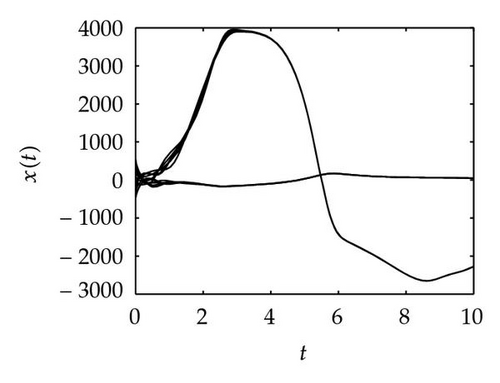
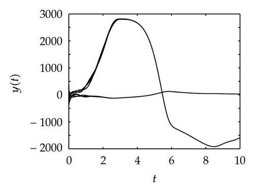
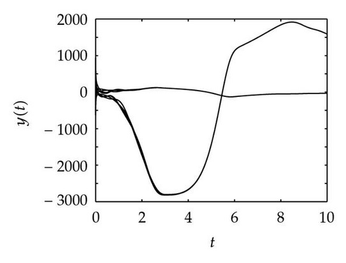
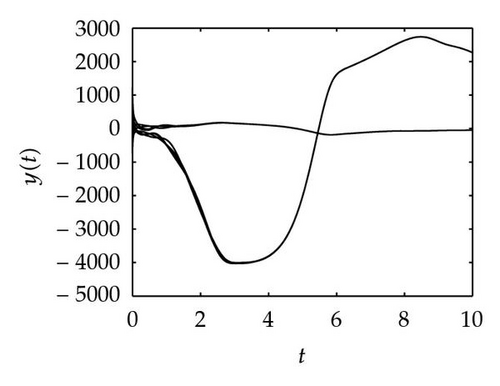
Simulation 1 The four graphs in Figure 1 represent the motion trace of drive and response systems. Comparing Figures 1(b), 1(c), and 1(d) with Figure 1(a), we can find a trivial conclusion. Because the parameters in response system and the ones in drive system are very similar, the shape of the motion orbit of response systems looks like the one of drive system. But the biases between the four traces and the “0” orbit is rather different.
Simulation 2 Setting θ = 1, μ = 1, π = 1, β = 1, γ = 1, δ = 1, it is easy to verify that Assumption 2.3 holds. Choose xij(t) = 100(12 − 3i − j) and xij(t) = 100(−8 + 3i + j) for t ≤ 0 as the initial values and define
In Figure 2, the top three plots present the synchronization process of drive system with α = 0.7, −0.7, −1, respectively; the middle three graphs demonstrate the change trend of Ey as t → ∞ with the former three projective factors; the bottom three ones represent the synchronization trace of the two neural networks for the three αs. The nine figures say that, for different α, the required synchronization times are all in the interval [4, 6]. However, the change amplitudes of the nine curves show obvious differences. By the same way, for the three projective factors, we can provide the three infimums of feedback control gains that are k ≥ 40.65 with α = 0.7, k ≥ 40.65 with α = −0.7 and k ≥ 39.33 with α = −1, respectively.
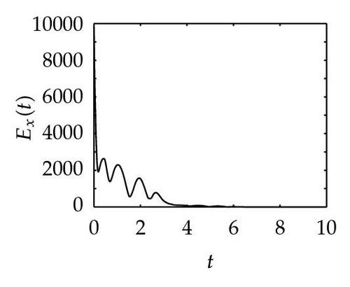
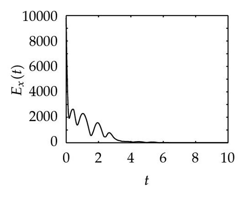
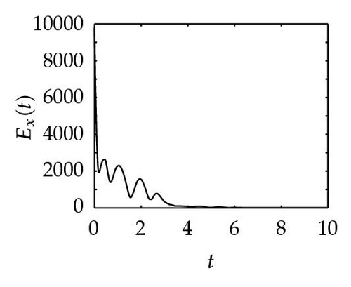
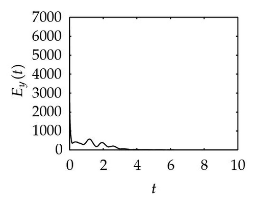
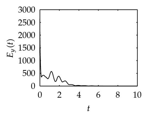
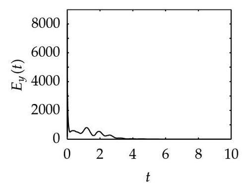
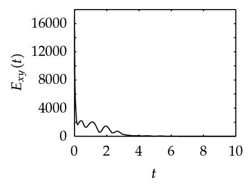
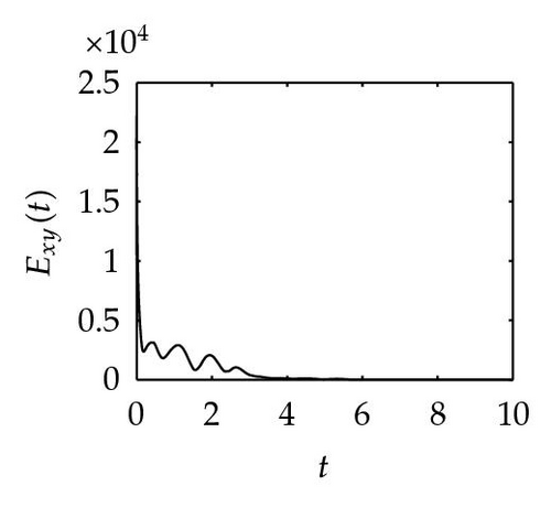
Remark 4.1. The reason why we apply three different nonlinear controllers for obtaining Theorems 1, 2, and 3 is that we want to find smaller feedback control gain. By computing, we have k ≥ 40.65 for Theorem 3.1, k ≥ 21.43 for Theorem 3.2, and k ≥ 20.43 for Theorem 3.4, respectively. It shows that our conjecture and simulation meet these results.
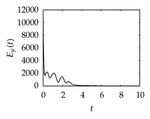
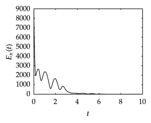
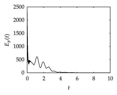
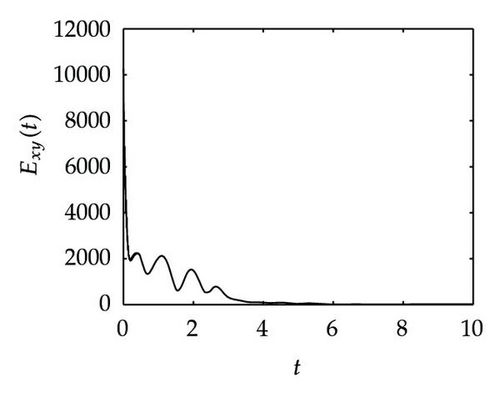
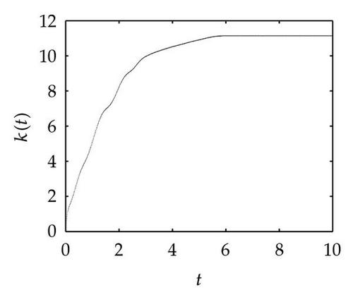
Simulation 3 In this simulation, we want to verify the synchronization process of the two neural networks when an adaptive control is applied to the response system. Figure 3 shows the time evolution of Ex, Ey, Exy and k(t), as well as the fourth plot Figure 3(d) tell us that the feedback control gain trends towards 11.15 approximately as t → ∞ which is far lower than 39.33. Actually, this proves that the adaptive control method can diminish the feedback control gain.
5. Conclusion
The GPS between two neural networks with mixed time delays and different parameters was investigated in this paper. By means of the Lyapunov stability theories, the GPS was realized under control of three nonlinear controllers. By comparison, we found that the nonlinear controller in Theorem 3.4 was simpler and easier to ensure that the GPS was achieved. Therefore, it was also applied in practical design. According to the optimal nonlinear controller, an adaptive update technique was designed to guarantee that the feedback control gain was sufficiently small. Eventually, several numerical simulations verified the validity of those results.
Acknowledgments
The authors thank the referees and the editor for their valuable comments on this paper. This work was supported by the National Science Foundation of China under Grant no. 61070087, the Guangdong Education University Industry Cooperation Projects (2009B090300355), the Foundation for Distinguished Young Talents in Higher Education of Guangdong (LYM11115), the Shenzhen Basic Research Project (JC200903120040A, JC201006010743A), and the Shenzhen Polytechnic Youth Innovation Project (2210k3010020).


