Study of Possible Obstacles Preventing Obtaining a Tokomak Regime in the Egyptian Machine
Abstract
The main goal of this study is to clarify the possibility to obtain the plasma discharge and to prolong its duration as much as possible, and to analyze what are the preventing reasons of obtaining this goal. Possible reasons can be improper operation of the power supply system, a high level of stray magnetic fields, lack of equilibrium, influence of MHD instabilities, and a high level of impurities. We analyze experimentally these possibilities and discuss them in more details.
1. Introduction and Experimental Facility
The Egyptian facility is a small device of rectangular cross section 25 × 20 cm. Its major (R) and minor (A) radius are 30 and 10 cm, respectively. The aspect ratio is 3. All the necessary electrical circuitry descriptions and its main parameters are given in [1].
The duration of the toroidal field pulse is long enough (~30 ms with charging half of its capacitor bank), so the time interval with relatively small (~20%) variation of the toroidal field is about 10 ms. That is why first of all we checked the operation of the ohmic heating power supply system. With the existing circuitry, it critically depends on the normal operation of a Vacuum Interrupter (VI) in the circuit of the so-called OH “slow” battery [1]. With an old VI there was no real interruption of the current because of arcing induced by poor vacuum internally. The installation of a new interrupter would take a lot of time (according to references available in EGYPTOR Tokamak Project Laboratory, a similar system on the COMPASS tokamak was operating correctly after six months of adjustment using special equipment not available in this laboratory) [2].
Because without the VI the OH “slow” battery could not give the loop voltage necessary for breakdown the discharge, we were forced to obtain the discharges with the help of only the OH “fast” battery which could provide a discharge duration of only ~1 ms. For simultaneous operation of both batteries the tokamak power supply system must be modified. For instance, the system described in [3] can be used.
2. Results and Discussions
2.1. Compensation of Stray Magnetic Fields
As the first step, the level of compensation of stray magnetic field with the help of permanent coils should be tested. The main sources of this field could be the toroidal field coils (due to their small misalignment) and the ohmic heating winding (because there is no iron core).
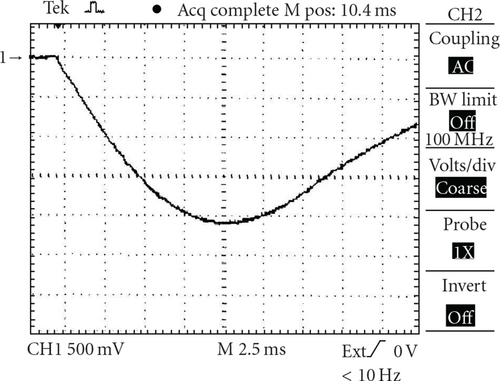
For measurements of the vertical magnetic field from the OH coil, a pick-up coil was used [1]. This coil was placed at the center of the plasma chamber. In Figure 1, one can see the wave-form of the stray magnetic field from the OH coil without compensation. The wave-form of this magnetic field with compensation is presented in Figure 2.
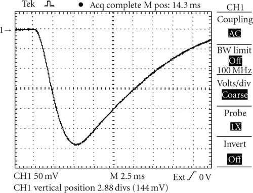
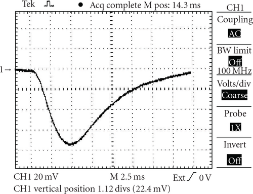
So one can see that the compensation reduces the stray magnetic field about 4.6 times. Taking into account that the sensitivity of the pick-up coil is B[T] = 0.017U[V] (where B is the magnetic field value and U is the signal value), and that in these experiments the voltage on the OH battery was 1 kV, one can find that the value of the stray magnetic field after compensation is about 1.2 × 10⁻³UOH[kV], where UOH is the OH battery voltage in kV.
The measurement of the vertical component of the toroidal magnetic field with the help of the same pick-up coil is practically impossible because it is very difficult to place this coil properly (see Figure 3).
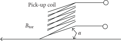
The plane of the pick-up coils must be parallel to the toroidal magnetic field Btor. If this condition is not met, a signal will be generated in the pick-up coil, which is proportional to sin α. In practice the value of this signal is much greater than the signal from the stray magnetic field.
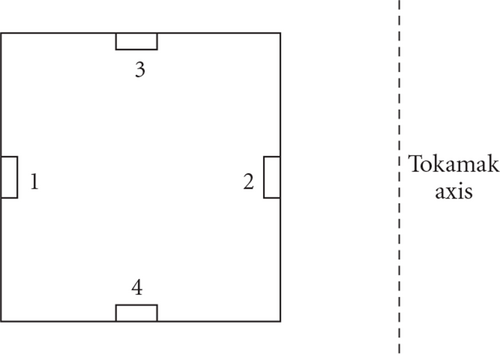
For measurements of the stray vertical field of the toroidal field coils, four (1–4) additional coils were used. These coils were placed on the bottom and top sides of the vacuum chamber as is shown in Figure 4.
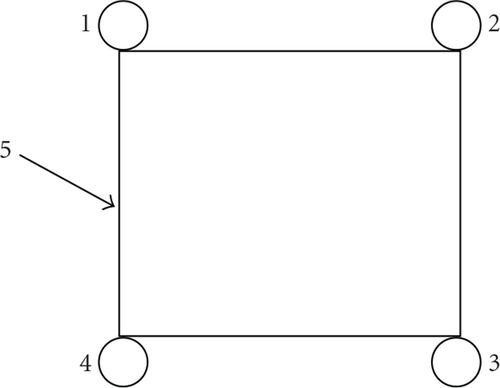
Coil 1 was connected with coil 2 in series as it can be seen in Figure 5.
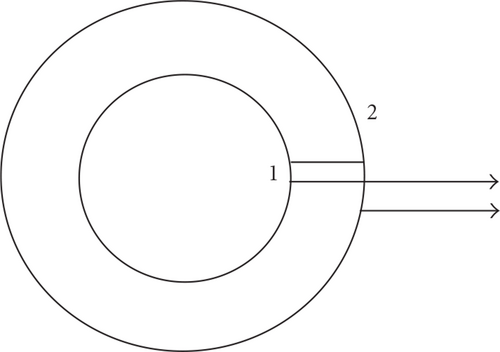
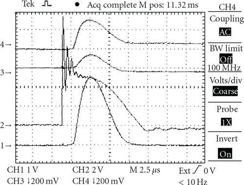
Coil 3 was connected with coil 4 in series, too. The difference between signals from loops 1 and 2 (or 3 and 4), which can be obtained after subtraction (or summation with opposite polarity) on a resistive divider, gives after integration the value of the vertical magnetic flux Ψ1-2 or Ψ3-4 between these two loops. Knowing their dimensions (radii) and, accordingly, the surface between them, , one can find the average vertical magnetic field . Absolute values of B⊥ field can be determined by comparison with measurements by a calibrated pick-up coil [3]. Since the effective surface of this coil equals to πD2N (D = 1.5 cm is its diameter, N = 120: number of turns), that is, 842 cm2, and surface S1-2 equals to π(452 − 152) = 5655 cm2, so with using the same integrator their sensitivities will differ by a factor 6.7 (loops are more sensitive). So the sensitivity of loops 1-2 is equal to 0.114 T/V. The waveform of the vertical component of the toroidal magnetic field is given in Figure 6.
In a similar manner, one can obtain estimations of the average horizontal magnetic field which determines the equilibrium in vertical direction. For this purpose one should combine the signals of loops 1 and 3 (or 2 and 4), but their effective surface in this case will be S1-3 = 2πR1,3Δz, where Δz is vertical distance between loops 1 and 3 (38 cm), that is, S1−3 = 10744 cm2.
The signal from 1 + 2 coils is given in Figure 6. Taking into account the radii of the inner and outer coils (15 and 45 cm), we can estimate the value of the stray vertical fields from toroidal coil and ohmic heating coil as being not higher than 5 Gs. So we can conclude that the measured values of stray magnetic fields cannot prevent the discharge breakdown and limit its duration.
2.2. Plasma Equilibrium
Because Mirnov probes and these loops were not calibrated, we could make only some estimations of the plasma equilibrium. If the center of the plasma current coincides with the center of the chamber (i.e., at equal distances from both probes) these signals must be equal (in cylindrical approximation). In a torus these signals will differ due the toroidicity by the ratio (R + b )/(R − b). Due to the lack of equilibrium, that is, displacement Δ of plasma current relative to chamber axis, the signal in one of Mirnov probes (outer) will increase ~Jp/(b − Δ) ((Jp/b)(1 + Δ/b) for small displacements). Analogously, the signal from inner probe will decrease as (Jp/b)(1 − Δ/b) and their difference will be ~2JpΔ/b2. So if we adjust the signals from these two Mirnov probes in accordance with their toroidicity and then subtract these signals, we will obtain the signal proportional to displacement of the plasma current. But as one can see from these signals (Figure 8) their shapes are similar and repeat practically the shape of plasma current signal.
The relative difference between these signals (or signal after their normalization and subtraction—Figure 9) is not more than 0.125 which corresponds to displacement of not more than 0.06 b, that is, ~0.5 cm.
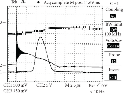
So we can conclude that the plasma equilibrium in these discharges is good enough and in any case could not be the reason for their short duration or small plasma current value.
2.3. MHD Instabilities
For Bt = 0.4 T (corresponding to Utor = 1 kV), plasma current Jp = 5 kA, and a = 7 cm, the q value equals to 1.7 · 103 · 0.4 · 49/5 · 103 = 6.7. This value is large enough because most dangerous MHD modes have q values of 2 and 3. So MHD instabilities most likely cannot be responsible for the short duration and the small amplitude of the plasma current.
2.4. Influence of Impurities
For a plasma current Jp = 5 kA and a loop voltage 25 V and assuming a = 7 cm, we obtain . This value is very close to the so-called “radiation limit” which was observed in first tokamaks and is associated with high level of impurities.
3. Counclusion
As an obvious way to improve the plasma performance in the EGYPTOR tokamak, we propose decreasing the level of plasma impurities and conditioning the chamber walls by discharge cleaning (50 Hz Taylor type and inductive) under the corresponding control of impurities content with the help of measurements of radiation power and/or spectroscopic impurity (carbon and oxygen first of all) behavior.
Moreover, for simultaneous operation of both OH “fast and slow” batteries, the tokamak power supply system must be modified. For instance, the system described in [3] can be used as it was seen to be valuable in other small Tokamaks.


