A Two-Disk Extended Jeffcott Rotor Model Distinguishing a Shaft Crack from Other Rotating Asymmetries
Abstract
A mathematical model of a cracked rotor and an asymmetric rotor with two disks representing a turbine and a generator is utilized to study the vibrations due to imbalance and side load. Nonlinearities typically related with a “breathing” crack are included using a Mayes steering function. Numerical simulations demonstrate how the variations of rotor parameters affect the vibration response and the effect of coupling between torsional and lateral modes. Bode, spectrum, and orbit plots are used to show the differences between the vibration signatures associated with cracked shafts versus asymmetric shafts. Results show how nonlinear lateral-torsional coupling shifts the resonance peaks in the torsional vibration response for cracked shafts and asymmetric rotors. The resonance peaks shift depending on the ratio of the lateral-to-torsional natural frequencies with the peak responses occurring at noninteger values of the lateral natural frequency. When the general nonlinear models used in this study are constrained to reduce to linear torsional vibration, the peak responses occur at commonly reported integer ratios. Full spectrum analyses of the X and Y vibrations reveal distinct vibration characteristics of both cracked and asymmetric rotors including reverse vibration components. Critical speeds and vibration orders predicted using the models presented herein include and extend diagnostic indicators commonly reported.
1. Introduction
The purpose of this investigation is to develop and test models for the vibration response of cracked and asymmetric shafts. Some asymmetries are geometric while others may be due to a shaft crack. In this paper, an asymmetric shaft refers to geometric asymmetry other than that due to a crack. The vibration response of asymmetric and cracked shafts shares characteristics such as 2x response which makes them hard to distinguish. A distinct crack diagnostic measure observable with measurable vibration data is a further goal of this study. This topic is widely studied because of possible sudden catastrophic failure of a rotor from fatigue. Stress concentrations and high-rotational speeds exacerbate the problem. This is especially dangerous because the torsional response of the rotor is often unmeasured and lightly damped. A comprehensive literature survey of various crack modeling techniques and system behavior of cracked rotor was given by Wauer [1]. This paper contains the modeling of the cracked components of the structures and searches for different detection strategies to diagnose fracture damage. A more recent survey paper by Sabnavis et al. [2] divides the current research into three categories: vibration-based methods, modal testing, and nontraditional methods such as wavelets or neural networks. Dimarogonas [3] provided an earlier literature review of the vibration of cracked structures and cites more than 300 papers. His review is categorized according to methods that describe local flexibility due to cracks, nonlinearities introduced into the system, and local stiffness matrix descriptions of the cracked section. The crack leads to a coupled system that can be recognized from additional harmonics in the frequency spectrum. The subharmonic resonances at approximately half and one third of the bending critical speed of the rotor are reported to be the prominent crack indicators by Gasch [4, 5] and Chan [6]. By utilizing a single parameter “hinge” crack model, Gasch provided an overview of the dynamic behavior of a simple rotor with transverse crack. He assumed weight dominance and employed a perturbation method into his analysis. Cross-coupling stiffness and dynamic response terms were not included in his analysis. Mayes model [7] is more practical for deep cracks than a hinged model. Based on Mayes modified model, Sawicki et al. [8, 9] studied the transient vibration response of a cracked Jeffcott rotor under constant acceleration ratios and under constant external torque. The angle between the crack centerline and the rotor whirl vector is employed to determine the closing and opening of the crack. This allows one to study the rotor dynamic response with or without the rotor weight dominance assumption by taking nonsynchronous whirl into account. Sawicki et al. [10] investigated the nonlinear dynamic response of a cracked one-mass Jeffcott rotor by means of bifurcation plots. When a rotor with the crack depth of 0.4 spins at some speed ranges, both the lateral and torsional vibration responses sustain periodic, quasiperiodic, or chaotic behavior. Some researchers [11, 12] have investigated using additional external excitations, such as active magnetic bearings, to create combination resonances for crack identification. Muszynska et al. [13] and Bently et al. [14] discuss rotor-coupled lateral and torsional vibrations due to unbalance as well as due to shaft asymmetry under a constant radial preload force. Their experimental results exhibited the existence of significant torsional vibrations due to coupling with the lateral modes. In Bently’s and Muszynska’s experiments, an asymmetric shaft was used to simulate the behavior of a crack.
This paper extends the research investigations of both Bently et al.’s [14] and Wu’s work [15, 16]. The unique features in this work are the use of full spectrum and the incorporation of Mayes and Davies [7] crack steering function into an extended Jeffcott rotor model. This causes the stiffness to change with orientation as opposed to the asymmetric stiffness model which is constant in a rotating coordinate system. Another difference is that the equations of motion herein are expressed and solved in inertial coordinates. While anisotropic shafts share some common characteristics with cracked shafts, the crack opening and closing introduce different behavior. Therefore, in this study, an accurate and realistic crack model is introduced for a two-mass rotor in which the first mass represents a turbine and the second mass represents a generator. Starting from energy equations, an analytical model with four degrees of freedom for a torsional/lateral-coupled rotor due to a crack is developed. A radial constant force is applied to the outboard disk to emphasize the effects of the gravity force which plays a critical role for the “breathing” of a crack. As preload increases, the vibration amplitudes in both lateral and torsional directions increase. The “second-order” nonlinear coupling terms due to a crack introduce supersynchronous peaks at certain rotational speeds, which is unique for a cracked rotor and might be used as an unambiguous crack indicator. Computer simulations also show that the rotational speeds at which amplitudes of the torsional vibrations reach maximum are governed by the ratio of lateral to torsional natural frequency.
2. Extended Jeffcott Rotor Mathematical Model
2.1. Physical System
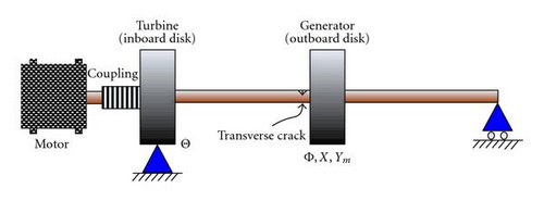
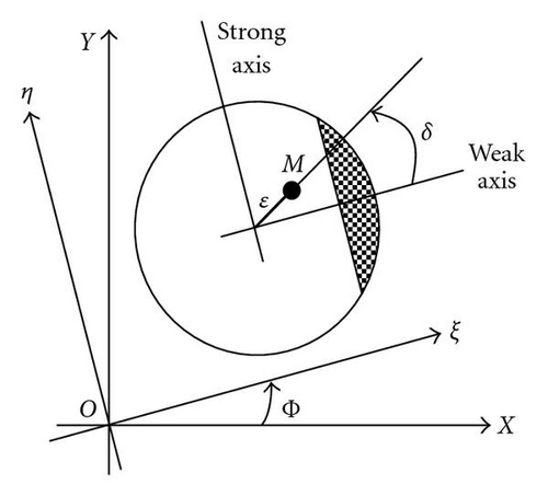
Figure 1 illustrates the system schematic configuration used to model a turbo machine with a cracked rotor or an asymmetry at the same location. The rotor is driven through a flexible coupling and is supported by bearings which constrain lateral motion. A crack or asymmetry is located near the outboard disk where a downward constant radial force P is also applied. The coupled torsional-flexural vibrations are modeled using four degrees of freedom; torsional rotation at each disk and lateral motion at the outboard disk. Figure 2 shows the section view of the cracked shaft in both inertial (X, Y), and rotating coordinates (ξ, η).
2.2. Equations of Motion
2.3. Cracked Shaft Equations of Motion
2.4. Asymmetric Shaft Equations of Motion
2.5. Special Cases
Case 1 (Pure Torsional Vibration for a Cracked Rotor). Assuming no lateral vibration, X = 0, Ym = 0, and a rigid drive coupling, , leads to the following simplification for the cracked shaft:
Case 2 (Pure Torsional Vibration for an Asymmetric Rotor). Assuming no lateral vibration, X = 0, Ym = 0, and a rigid drive coupling, , leads to the following simplification for the asymmetric shaft:
3. Numerical Results and Discussion
3.1. Pure Torsion
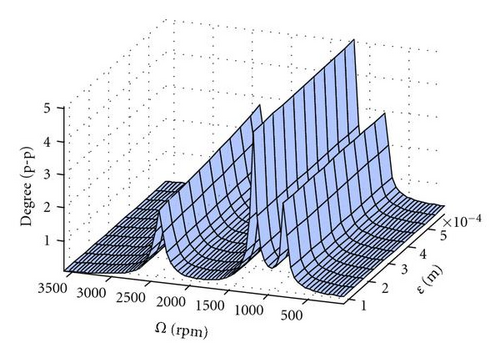
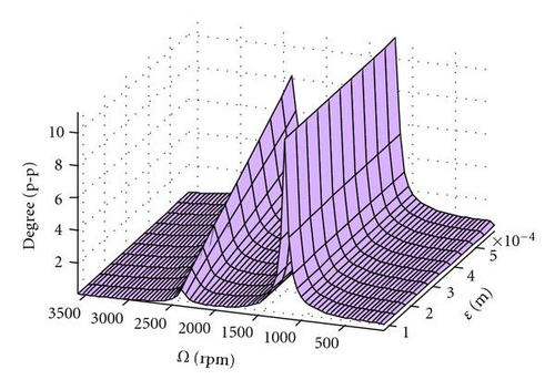
Computer simulation results using the parameters in Table 1 for the special cases listed above are shown in Figure 3. The response for a cracked shaft which is calculated from (18) can be interpreted as a nonlinear oscillator with 1x excitation {(P ε/4I)(Δk1 − Δk2)cos Φ+(P2/8KI)(−Δk1 + Δk2/2)sin Φ}, 2x excitation {(P ε/8I)(Δk1 − Δk2)cos 2Φ + (P2Δk2/4KI)sin 2Φ}, and a 3x excitation {(3P2Δk2/16KI)sin 3Φ} due to the unbalance, the depth of the crack, and the side load. These excitations cause the critical speeds shown in Figure 3(a). For the asymmetric shaft, the steady-state responses seen in Figure 3(b) and calculated from (21) can be interpreted as response to 1x{−(qP ε/I)cos (Φ − δ)} and 2x excitations {(qP2/KI)sin 2Φ}. Since lateral motion is restrained, only torsional critical frequencies appear. For the cracked shaft, there is a 3x critical speed in addition to 1x and 2x. For the parameters in Table 1, the 2x response is the largest. Further details of the dependence of the magnitude of response to crack depth can be found in [16].
| Cracked shaft | Asymmetric shaft | ||||
|---|---|---|---|---|---|
| Parameters | Values | Units | Parameters | Values | Units |
| ωn | 12000 | rpm | ωn | 12000 | rpm |
| ωt | 2400 | rpm | ωt | 2400 | rpm |
| ε | 7.62×10⁻⁵ | m | ε | 7.62×10⁻⁵ | m |
| ρ | 0.0241 | m | ρ | 0.0241 | m |
| P/M | 1270 | m/s2 | P/M | 1270 | m/s2 |
| ζt | 0.02 | ζt | 0.02 | ||
| Δkξ/K | 0.30 | q | 0.14 | ||
| δ | 0 | rad | δ | 0 | rad |
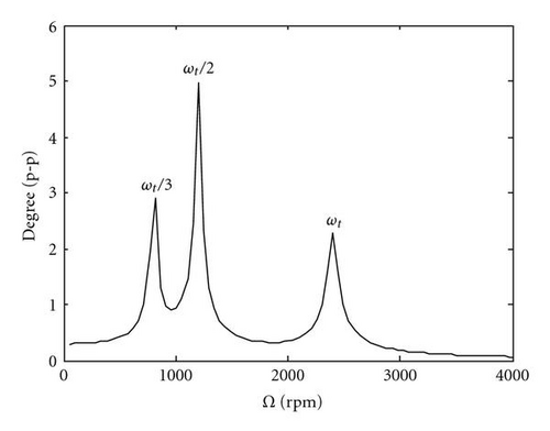
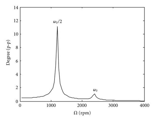
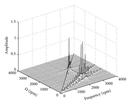
Figure 4 depicts the response for the same system described in Table 1 except that the response is plotted for a range of eccentricities. For the cracked shaft and the asymmetric shaft, the critical speed associated with the 1x torsional natural frequency at 2400 rpm has a magnitude that increases with increasing eccentricity. The response at the other critical speeds is independent of eccentricity. The consequence of this is that for well-balanced shafts, the presence of a crack will be more easily detected by monitoring the response at a shaft-rotative speed of ωt/2 or ωt/3. At large values of eccentricity, the response at shaft-rotative speeds equal to the torsional natural frequency dominates. The sensitivity of response to changing eccentricity is much greater for the asymmetric shaft. The frequency response at various shaft-rotative speeds, Ω, using the parameters in Table 1 is depicted in Figure 5. Each is dominated by 2x responses with an additional 3x-order response for the cracked shaft.

3.2. Lateral and Torsional Coupled Vibrations
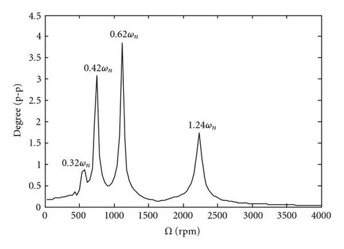
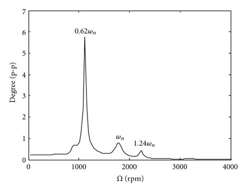
When the parameters shown in Table 2 are used in the general four degrees of freedom model, the critical frequencies shift as seen by comparing Figure 3(a) to Figures 6(a), 6(b) and Figure 3(b) to Figures 7(a), 7(b). Lateral/torsional coupling causes the lateral natural frequency ωn to appear in the torsional response. Also, critical speeds are no longer at integer fractional multiples of the torsional natural frequencies. Instead of a given ratio of torsional to lateral natural frequency, critical speeds occur at fixed noninteger multiples of the lateral natural frequency. This is shown by comparing Figure 6(a) to Figure6(b) and Figure 7(a) to Figure7(b). The damaged shaft has a lower natural frequency so that 1.24 ωn corresponds to 0.90 ωt. Although the absolute frequencies have shifted, the relative critical speeds appear as 1/4, 1/3, and 1/2 of this value. Further details about the variations of the critical speeds due to different stiffness ratios, ωt/ωn, can be found in [16]. By comparing Figure 6 to Figure 7, it is shown that the coupling causes some frequencies to appear in both the asymmetric and cracked shafts, while others appear only in the cracked shaft. The P/M values used in the plots are set intentionally large for the parametric study in order to easily illustrate the coupling and to reproduce values from a paper upon which this study is based [14]. Smaller values would lead to lower peaks and sometimes change the peak response to a different critical speed.
| Cracked shaft | Asymmetric shaft | ||||
|---|---|---|---|---|---|
| Parameters | Values | Units | Parameters | Values | Units |
| ε | 5.08×10⁻⁵ | m | ε | 5.08×10⁻⁵ | m |
| ρ | 0.0229 | m | ρ | 0.0229 | m |
| P/M | 101.6 | m/s2 | P/M | 101.6 | m/s2 |
| ζt | 0.02 | ζt | 0.02 | ||
| ζ | 0.1 | ζ | 0.1 | ||
| Kr | 5 | Kr | 5 | ||
| Cr | 1 | Cr | 1 | ||
| Δkξ/K | 0.38 | q | 0.18 | ||
| δ | 0 | rad | δ | 0 | rad |
| Cracked shaft | Asymmetric shaft | ||||
|---|---|---|---|---|---|
| Parameters | Values | Units | Parameters | Values | Units |
| ωn | 2400 | rpm | ωn | 2400 | rpm |
| ωt | 3312 | rpm | ωt | 3312 | rpm |
| ε | 5.08×10⁻⁵ | m | ε | 5.08×10⁻⁵ | m |
| ρ | 0.0229 | m | ρ | 0.0229 | m |
| P/M | 101.6 | m/s2 | P/M | 101.6 | m/s2 |
| ζt | 0.02 | ζt | 0.02 | ||
| ζ | 0.1 | ζ | 0.1 | ||
| Kr | 5 | Kr | 5 | ||
| Cr | 1 | Cr | 1 | ||
| RI | 1 | RI | 1 | ||
| Δkξ/K | 0.30 | q | 0.18 | ||
| δ | 0 | rad | δ | 0 | rad |
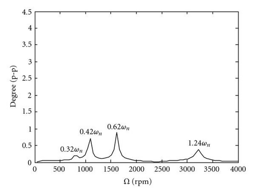

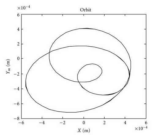
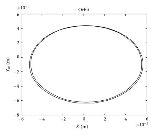
The steady-state response at one third of the lateral natural frequency is shown in Figure 8. The trajectory of the whirl for the cracked shaft undergoes three loops per shaft revolution, whereas the trajectory for the asymmetric shaft has a double elliptical pattern.
The full spectrum of the lateral vibration response as illustrated in Figure 9 demonstrates the advantage of using full-spectrum plots to differentiate between crack asymmetries and geometric asymmetries. The full spectrum for the cracked shaft includes reverse order response at −1x in addition to 1x and the supersynchronous responses at 2x and 3x. The asymmetric lateral shaft response contains only 1x and 2x without any reverse vibration components.


4. Conclusions
This paper documents the effect of a shaft crack versus other geometric asymmetries on lateral and torsional vibrations of a two-mass rotor system. Nondimensional analytical models of extended Jeffcott rotors are derived from Lagrange’s equations taking into consideration the lateral/torsional vibration coupling mechanism induced by a “breathing” crack or a geometric asymmetry. Four degrees of freedom describe the models; two lateral displacements, one torsional angular displacement of an outboard disk, and the torsional angular displacement of an inboard disk. The nonlinearities associated with a breathing crack or geometric asymmetry couple the four equations of motion. Two cases are considered in this work: a torsionally rigid rotor without lateral vibration and a general unconstrained solution to the four degrees of freedom model presented. The first case is characterized by torsional vibrations which occur at Ω = ωt/3 and Ω = ωt/2. For a cracked shaft, a 3x torsional vibration also occurs. The general case makes evident the existence of strong coupling between lateral and torsional vibrations where vibration amplitude increases with crack depth, stiffness asymmetry, and radial load. Nonlinear lateral-torsional coupling from a crack shifts the resonance peaks in the torsional vibration response. The resonance peak frequencies shift depending on the ratio of the lateral to torsional natural frequencies with the peak responses occurring at fixed noninteger values of the lateral natural frequency. Orbit plots can also be used to identify a crack with patterns distinguishable from other geometric asymmetries. The distinct vibration signatures predicted by this model can be used for shaft crack diagnostic purposes.
Nomenclature
-
- ωn, ωt:
-
- Lateral and torsional natural frequencies, respectively
-
- Θ:
-
- Angular location of inboard disk
-
- θ:
-
- Angular displacement of the inboard diskrelative to motor
-
- θ0:
-
- Initial angular location of inboard disk
-
- Φ:
-
- Angular location of outboard disk
-
- φ:
-
- Angular displacement of the outboard disk relative to motor
-
- φ0:
-
- Initial angular location of outboard disk
-
- I0:, I
-
- Inboard and outboard disk polar moments of inertia, respectively
-
- δ:
-
- Angular orientation of outboard disk eccentricity
-
- Γc:
-
- Lateral coupling terms in outboard disk equation of motion
-
- M:
-
- Outboard disk mass
-
- P:
-
- Vertical side load
-
- X, Y:
-
- Outboard disk lateral motion in inertial coordinates
-
- xcm, ycm:
-
- Locations of the center of mass of outboard disk
-
- Kr:
-
- Stiffness ratio: Kc/Kt
-
- Cr:
-
- Camping ratio: Cc/Ct
-
- RI:
-
- Polar moment of inertia ratio: I/I0
-
- ξ, η:
-
- Rotor-fixed rotating coordinates
-
- Ym:
-
- Dynamic vertical vibration in inertial coordinates
-
- ε:
-
- Eccentricity of outboard disk
-
- Ω:
-
- Motor speed
-
- Cc, Kc:
-
- Motor-shaft coupling damping and stiffness, respectively
-
- C, Ct:
-
- Lateral and torsional damping coefficients, respectively
-
- ζ, ζt:
-
- Lateral and torsional damping ratios, respectively
-
- Kt:
-
- Torsional shaft stiffness
-
- K:
-
- Uncracked shaft lateral stiffness or average stiffness for asymmetric shaft
-
- KIc:
-
- Stiffness matrix of cracked shaft in inertial coordinates
-
- KIasym:
-
- Stiffness matrix of asymmetric shaft in inertial coordinates
-
- KR:
-
- Stiffness matrix of asymmetric shaft in rotating coordinates
-
- f(Φ):
-
- Crack steering function
-
- ρ:
-
- Radius of gyration
-
- Δkξ, Δkη:
-
- Reduced stiffness in ξ and η directions, respectively
-
- q:
-
- Stiffness asymmetry factor.
Acknowledgments
This work was sponsored by the Department of the Navy, Office of Naval Research under Award no. N00014-06-1-1111. This support is gratefully acknowledged. The authors also wish to acknowledge the support of the Donald E. Bently Center for Engineering Innovation at California Polytechnic State University, San Luis, Obispo.


