An In Vitro Study to Determine the Effectiveness of a Patellar Ligament/Fascia Lata Graft and New Tibial Suture Anchor Points for Extracapsular Stabilization of the Cranial Cruciate Ligament–Deficient Stifle in the Dog
Dr. Harper's current address is School of Veterinary Medicine, Faculty of Medical Sciences, The University of the West Indies, St. Augustine, Trinidad, West Indies. Supported by a grant from the Virginia Veterinary Medical Association/Virginia-Maryland Regional College of Veterinary Medicine—Veterinary Memorial Fund.
Presented 2002 American College of Veterinary Surgeons Annual Meeting and 12th Annual Veterinary Symposium, San Diego, CA.
Abstract
Objective— (1) To determine whether an extracapsular patellar ligament/fascia lata graft would provide stability in the cranial cruciate ligament (CrCL)-deficient stifle comparable with that of the intact stifle. (2) To determine if different tibial anchor points would enhance stability of the CrCLdeficient stifle when compared with the standard fabellar-tibial suture (FTS) placement.
Study Design— Experimental.
Animals— Twenty-eight canine cadaver hind limbs.
Methods— Stifles were mounted in a jig and tested between loads of −65 and 80 N. After testing the intact CrCL, 4 stabilization techniques were tested after CrCL transection: lateral graft technique (LGT) and 3 FTS with different tibial anchor points.
Results— There were no significant differences in displacement between the LGT and standard FTS, between the LGT and the intact CrCL, or between the FTS and the intact CrCL, in either the Securos™ or the Screw–washer experiments. Stiffness of the intact CrCL was significantly greater than that of any stabilization technique and the cut CrCL. The standard FTS showed the least displacement of all suture stabilization techniques. Differences in stiffness were not significant between the suture stabilization techniques.
Conclusions— Securely anchored, the LGT results in a reduction in drawer motion similar to that of the intact CrCL and the standard FTS. Altering the tibial anchor point for the FTS does not improve stiffness or enhance stabilization of the CrCL-deficient stifle.
Clinical Relevance— The LGT could be used for the treatment of CrCL ruptures in the dog. A clinical study is recommended.
Introduction
CRANIAL CRUCIATE LIGAMENT (CrCL) rupture is one of the most common causes of hind limb lameness in dogs,1,2 leading to stifle instability, pain, and chronic lameness.3,4 Degenerative joint disease (DJD) is the usual outcome and is characterized by osteophytosis and articular erosions.4 Meniscal damage is a common secondary finding.4–6 Numerous surgical techniques have been described to stabilize the CrCL-deficient stifle;3,7–18 however, no technique has been shown to consistently arrest the development or the progression of DJD.19–21 Objectives of surgery are to provide normal joint mechanics and stability, relief of pain, and prevention of secondary meniscal tears, and to prevent the development of further DJD.20,22,23
Surgical techniques are divided into intracapsular and extracapsular procedures. Extracapsular techniques are advantageous when intracapsular repairs cannot be used, e.g., failure of an intracapsular technique or after joint infection.3,23 Other complications associated with intracapsular graft techniques include potential failure of the graft because of a delay in ligamentization (>20–24 weeks)25,26 resulting in poor mechanical properties of the graft, particularly in an unfavorable joint environment (e.g., severe DJD). A survey showed that most veterinary surgeons preferred extracapsular techniques for the repair of CrCL ruptures in the dog.27 Analysis of a mathematical model for optimizing the attachment sites of an extracapsular suture for stabilization of the CrCL-deficient stifle has been reported.28 Selecting an isometric origin and insertion point both proximal and distal to the canine stifle joint has been suggested as a way to optimize the function of an extracapsular suture.28
The use of autogenous tissues for cruciate repair in veterinary medicine is not new.11,12,17,29 The lateral graft technique (LGT), modified from the original MacIntosh procedure24 used in human orthopedics for anterior cruciate ligament reconstruction, involves the use of a combined patellar ligament and fascia lata graft placed in an extracapsular fashion from the tibial crest to the femorofabellar ligament. An extracapsular fascial strip technique in which the fascial strip is sutured to itself, the patellar ligament, the femorofabellar ligament, and the lateral collateral ligament, and combined with a medial buttress suture has been successfully used in clinical patients.30 The effectiveness of the graft alone has not been tested. A technique for stabilization of the CrCL-deficient stifle that can be used in medium to large breed dogs that requires minimal implants or uses biological implants is easy to perform, has a low complication rate, effectively stabilizes the stifle joint, and repeatedly results in a successful outcome would be the ideal technique, particularly in general practice.
Our study aims were: (1) to determine whether a pedicle graft of fascia lata and the lateral one-third of the patellar ligament, with its base on the proximal tibia, would confer stability in the CrCL-deficient stifle comparable with that of the intact CrCL or standard fabellar-tibial suture (FTS) placement, and (2) to determine if changing placement of the tibial anchor point for the FTS from the tibial crest to either the cranial or caudal prominence of the extensor groove (EG) would result in improved stiffness or enhanced stabilization of the CrCL-deficient stifle.
Materials and Methods
Canine cadaver hindlimbs were obtained and a fascia lata/patellar ligament graft was harvested. Once a specimen was prepared and potted, the stifle construct was placed in a jig and tested with the CrCL intact. The stifle constructs were then tested with each of the stabilization techniques after CrCL transection. The stabilization techniques were: (1) the LGT; (2) the standard FTS with the tibial suture anchor point through a hole in the tibial crest; (3) the FTS with the tibial suture anchor point through a hole in the cranial prominence of the EG; and (4) the FTS with the tibial suture anchor point through a hole in the caudal prominence of the EG.
Three experiments were performed with the LGT and the 3 suture stabilization techniques done in each of the 3 experiments. The differences between the 3 experiments were the methods used to secure the graft (staples versus screw and washer); the method used to secure the FTS (Securos™, Securos Inc., Charlton, MA, versus hand ties); and the size of nylon used for the FTS (50 or 80 lb). Table 1 summarizes the techniques and number of stifles used in each experiment.
| Experiment | Number of Stifles Tested | Method of Graft Fixation | FTS Suture and Method of Fixation |
|---|---|---|---|
| Securos™ | 10 | Screw and spiked washer | 80 lb. nylon leader Securos™ system |
| Staple | 10 | Electric stapler | 50 lb. nylon leader Hand ties |
| Screw–washer | 8 | Screw and spiked washer | 50 lb. leader Hand ties |
- Methods used for fixation of the grafts as well as the type of suture and the method of suture fixation are summarized.
Sample Collection and Preparation
Twenty-eight hind limbs were harvested from skeletally mature, male and female dogs (22–36 kg). The hind limbs were obtained immediately after death and skeletal maturity was determined fluoroscopically before study inclusion. Each hind limb was disarticulated at the coxofemoral joint. The specimen included the femur, tibia, and surrounding musculature. The skin was removed and the limbs were rinsed with saline (0.9% NaCl) solution and then individually wrapped in saline-soaked paper towels before being placed in plastic bags and frozen at −8°C.
Thawing before testing was achieved by leaving the plastic bag containing the frozen specimen immersed in a container of tap water overnight in a refrigeration room at 4°C. On the day of testing, the graft was harvested before dissection and removal of the musculature from the limb. The subcutaneous fat and superficial fascia were dissected away from the deeper fascia lata. A number 15 scalpel blade was used to make a 1-cm longitudinal stab incision in the lateral one-third of the mid-portion of the patellar ligament without incising the joint capsule. This incision was made at the junction of the middle and lateral thirds of the patellar ligament so that the lateral one-third of the patellar ligament would be included in the graft. Another 1-cm incision was made in the most proximal aspect of the tensor fascia lata at a point 6–10 cm proximal to the patella at the cranial margin of the cranial sartorius muscle. This incision was extended distally along the lateral margin of the patella to connect with the first incision in the patellar ligament, forming the craniomedial margin of the graft. The width of the graft distally was determined by the distance between the incision in the patellar ligament and the caudolateral aspect of the attachment of the fascia lata atthe prominence on the cranial border of the EG of the tibia. Beginning at the most proximal portion of the graft and maintaining its predetermined width, the fascia lata was cut parallel to the craniomedial margin of the graft, forming its caudolateral margin. The distal portion of the fascia lata (where it blends with the fascia of the stifle joint and unites with the patellar ligament) and the distal attachment of the patellar ligament on the tibial crest,31 were preserved (Fig 1).
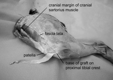
Harvested graft lifted away from the underlying musculature, showing the preserved tibial attachment.
Once the graft was harvested, the musculature on the femur and tibia was removed except for a 1-cm length of the lateral head of the gastrocnemius muscle distal to the lateral fabella. The patella and joint capsule were removed. Gross evidence of DJD was determined once the joint capsule was removed. Stifles with evidence of DJD were not included in the study. The remaining portion of the patellar ligament that was not used in the graft was removed except for a 1-cm portion at its attachment to the tibial crest. The fascial graft, medial and lateral collateral ligaments of the stifle, and the cruciate ligaments and menisci were left intact. The stifle was wrapped in clear plastic wrapping and moistened with saline. The plastic wrapping kept the soft tissues moist during potting and testing.
Potting. After harvesting the graft and removal of the musculature, the tibia and femur were individually potted using a polyester resin (Bondo®, Bondo Corporation, Atlanta, GA) before testing. Both were cut to 11.43–12 cm in length, measured from the stifle (femorotibial) joint. Bones were each potted in a 6.35 cm deep aluminum cylinder that allowed centering of the bones in the resin. The potted construct was fixed in the testing apparatus for biomechanical testing (Fig 2).
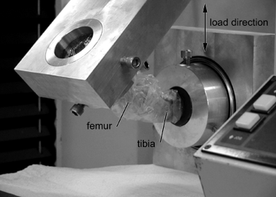
Loaded construct ready for testing. The construct is wrapped in plastic to keep the soft tissue moist.
Stifle Stabilization Techniques
LGT. A curved mosquito hemostat was passed in a craniocaudal direction through a small stab incision made parallel to the fibers in the middle of the lateral femorofabellar ligament. The stifle was held at 135° of flexion and the free end of the previously harvested graft was grasped in the tip of the hemostat and pulled caudal to the fabella and gastrocnemius muscle stump and through the femorofabellar ligament cranially. Tension was applied until cranial drawer motion was eliminated and the graft was then secured to the craniolateral aspect of the distal femur just proximal to the trochlear groove. The LGT was used on all stifles; however, 2 different methods were used to secure the graft to the distal femur: (1) 4.5 mm screws (Synthes®, Philadelphia, PA) and spiked washers (Imex™, Longview, TX) were used in 18 stifles and (2) two 8 mm Arrow # T50 staples were inserted with a heavy duty Sharpshooter™ TRE500 electric stapler (Stanley® Fastening Systems, East Greenwich, RI) to secure the graft on the distal femur in 10 stifles (Fig 3).
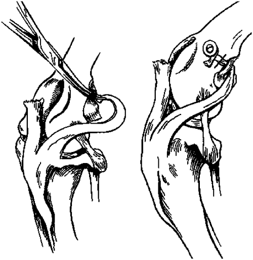
Illustration showing the lateral graft being pulled caudal to the lateral fabella and through the femorofabellar ligament using a hemostat and then secured to the distal femur with a screw and washer or staples. (Solid line represents the direction in which staples were placed across the graft when staples were used.)
FTS with the tibial anchor point in the tibial crest (FTS: tibial crest). A curved Securos™ J-needle (Securos Inc.) loaded with either Mason (Mason Original Hard Type Monofilament Nylon Leader Material, Mason, Tackle Co., Otisville, MI) 50-lb test nylon leader or 80-lb test monofilament nylon leader (Securos Inc.) was passed through the femorofabellar ligament in a proximal to distal direction, around the lateral fabella. The same technique was used to place the nylon through the femorofabellar ligament and around the lateral fabella for all suture stabilization techniques.
A 3/32″ Steinmann pin was used to drill a hole through the tibial crest, from medial to lateral, 1 cm caudal to the attachment of the patellar ligament (Fig 4). The distal end of nylon was passed through this hole from medial to lateral and secured to the proximal end, forming a figure-of-eight configuration. The suture was secured using either hand ties (with the knot placed at the level of the proximal aspect of the fabella) or the Securos™ 80-lb. Cranial Cruciate Ligament Repair System™ (Securos Inc.).

Location of the extensor groove and tibial suture anchor points for the three FTS techniques (a, tibial crest; b, cranial prominence of the extensor groove; c, caudal prominence of the extensor groove; white arrow, extensor groove).
FTS with the Tibial Anchor Point in the Cranial Prominence of the EG (FTS: Cranial EG). A 3/32″ Steinmann pin was used to drill a hole in a proximal to distal direction in the cranial prominence of the EG on the tibial plateau. The hole was made just cranial to the tibial attachment of the intermeniscal ligament at the level of the caudal edge of the fat pad32 (Fig 4). The distal end of nylon was passed through this hole in a proximal to distal direction and secured to the proximal end, forming a figure-of-eight configuration. The suture was secured using either hand ties (with the knot placed at the level of the proximal aspect of the fabella) or the Securos™ 80-lb Cranial Cruciate Ligament Repair System™.
FTS with the Tibial Anchor Point in the Caudal Prominence of the EG (FTS: Caudal EG). A 3/32″ Steinmann pin was used to drill a hole in a proximal to distal direction in the caudal prominence of the EG. The hole was centered on this prominence with the long axis of the pin parallel to the sagittal plane of the lateral femoral condyle (Fig 4). The distal end of nylon was passed through this hole in a proximal to distal direction and secured to the proximal end forming a figure-of-eight configuration. The suture was secured using either hand ties (with the knot placed at the level of the proximal aspect of the fabella) or the Securos™ 80-lb. Cranial Cruciate Ligament Repair System™.
Mechanical Testing
The stifle construct was first tested with the CrCL intact. The testing procedure followed the design described in 2 previous studies33,34 with 2 modifications: (1) the potting cylinders holding the femur and tibia were individually mounted in a jig so that a normal stifle angle of 135° was maintained throughout testing (Fig 2), and (2) the tibial potting cylinder was mounted on ball bearings that allowed rotation of the tibia about its long axis during testing (Fig 5). Markings on the tibial cylinder allowed an estimation of the amount of rotation occurring during testing. The plate holding the tibial potting cylinder was also mounted on doubled plates with ball bearings between the 2 plates. This allowed movement of the tibia in the plane parallel to its long axis, i.e., parallel to the floor, when the construct was loaded in the jig.
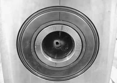
Back of the tibial potting cylinder showing double cylinders (ball bearings are located between the two cylinders) with 5° marks for estimating rotation.
The construct was placed in the jig with the femur in the top cylinder and the tibia in the bottom cylinder. A laser beam was mounted at the top of the jig and was used for alignment. The beam ensured that all specimens were similarly centered at the intercondylar space on the caudal aspect of the femur (Fig 6). Three screws on each cylinder were used to lock the specimens in place after centering. Once the cylinders were secured it was noted that there were load and displacement readings for the specimen on the X–Y recorder. During loading of the specimen the crosshead was manipulated to facilitate ease of loading and this may have placed some strain on the soft tissues. The crosshead was therefore manipulated while the tibia rotated within the tibial cylinder and the tibial plate moved freely until a zero displacement was recorded. This was established as the “zero” point for the specimen. A permanent marker was used to make corresponding marks on the aluminum cylinders and the resin holding the specimens to ensure that the original positions of the potted specimens were maintained at the start of each new treatment. The laser beam and the marks ensured that each construct was remounted in the same position after removal from the jig.
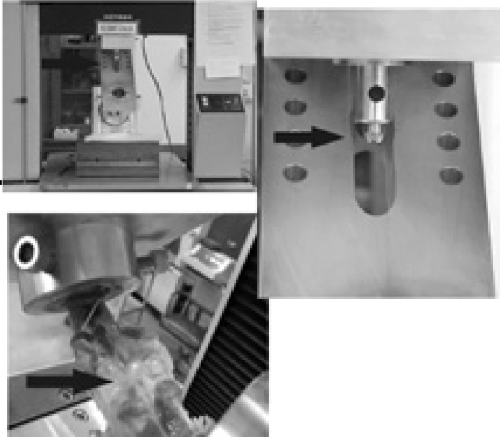
Laser beam mounted on the jig centered on the caudal intercondylar space.
The jig was fixed to an electrically driven mechanical testing machine (Instron—model 4468, Universal Testing Machine, Carlton, MA) that applied a load to the stifle being tested. When the crosshead displaced the femur so that the femur moved in a caudal direction on the tibial plateau (similar to cranial drawer motion in the CrCL-deficient stifle) this was referred to as cranial drawer. When the crosshead displaced the femur so that the femur moved in a cranial direction on the tibial plateau, this was referred to as caudal drawer. Loads of –65 N (caudal drawer) to 80 N (cranial drawer) were applied in cycles at a crosshead speed of 25 mm/min. Testing was done below the crosshead. The construct was loaded through 12 cycles and displacement of the femur in relation to the tibia and stiffness for each test were determined. A pilot study had revealed that reproducible load–deformation curves were attained through 12 cycles of loading.
Once the stifle construct with the intact CrCL was tested, the construct was removed from the jig, the plastic wrapping removed and the CrCL was transected using a number 11 scalpel blade. The construct was then replaced in the jig after application of a treatment. Each stabilization method (LGT and 3 FTS with different tibial anchor points) as well as the transected CrCL was considered a treatment. One treatment was removed before application of another treatment. The plastic wrapping was temporarily removed from the constructs each time a treatment was performed. Whenever the plastic wrapping was removed saline solution was dripped onto the specimens to keep tissues moist until the treatment was complete. The wrapping was then reapplied before replacing the construct in the jig for each test. Each stifle construct was considered a block and the order of treatments was randomized separately for each block. Twelve measurements were taken for each variable (displacement and stiffness) for each treatment. The 12 measurements from each treatment were considered subsamples. Load–displacement curves were generated for all cycles of all treatments. Displacement was measured as the distance in millimeters between −25 and +25 N (Fig 7). Stiffness was calculated as the slope of the line between 60 and 80 N (Fig 7).
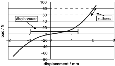
Load–displacement curve showing points (−25 and 25 N) between which displacement was measured.
Data Collection
Data were collected simultaneously during testing using a computerized data acquisition system (Labview 5.0 Graphical Programming for Instrumentation, National Instruments Version 5.0.1, Austin, TX). Table 1 summarizes the 3 experiments conducted during this study.
When the Securos™ 80 lb. Cranial Cruciate Ligament Repair System™ was used, the tensioning device was advanced in 1-click increments to 1 click beyond the point at which cranial drawer motion was eliminated. When 50 lb. nylon leader and hand ties were used, a slipknot was used and the suture was tightened at the level of the proximal aspect of the lateral fabella until cranial drawer motion was eliminated. Asquare knot was then placed on top of the slipknot. The primary investigator made all assessments of cranial drawer motion.
Statistical Analysis
For each of the 3 experiments, the mean for displacement and for stiffness for the 12 cycles in each treatment was calculated for each stifle. The MIXED procedure of the SAS System (ver. 8.2, SAS Institute Inc., Cary, NC) was used to perform an ANOVA to test the hypothesis that all treatment means were equal while controlling for the stifle. The Tukey–Kramer multiple comparison procedure was used for pairwise comparisons between treatment means in each experiment. Differences between treatment means were considered significant at P<.05.
Results
Securos™ Experiment
Mean values for displacement and stiffness are shown in Table 2. Displacement was greatest for the transected (cut) CrCL (12.03 mm) and least for the intact CrCL (1.75 mm). LGT resulted in the least displacement of all stabilization techniques (2.69 mm) and was not significantly different from the intact CrCL (P=.44) or the FTS: tibial crest (P=.91). When compared with each other there was no significant difference in displacement between the LGT, FTS: tibial crest, or the FTS: cranial EG.
| Stabilization Technique | Securos™ Experiment | Screw–Washer Experiment | Staple Experiment | |||
|---|---|---|---|---|---|---|
| Displacement | Stiffness | Displacement | Stiffness | Displacement | Stiffness | |
| Intact cruciate | 1.75a | 93.10d | 1.93a | 90.00d | 2.03a | 88.51d |
| Cut cruciate | 12.03d | 62.62c | 11.68d | 65.37c | 12.85d | 61.18c |
| LGT | 2.69ab | 38.13a | 3.03ab | 38.19a | 7.81b | 47.35a |
| FTS: tibial crest | 3.21ab | 43.89ab | 2.92ab | 43.03ab | 4.38ac | 40.20a |
| FTS: cranial EG | 4.12b | 46.28b | 4.26bc | 46.65b | 4.79ac | 42.19a |
| FTS: caudal EG | 5.96c | 48.66b | 5.36c | 50.34b | 6.19bc | 48.37a |
| Standard error of the mean | 0.37 | 1.89 | 0.46 | 2.20 | ∼0.70 | 2.60 |
- Means within the same column with no superscript letters in common are significantly different at α=0.05 according to Tukey's HSD.
Stiffness was greatest for the intact CrCL (93.1 N/mm), which was significantly different from the cut CrCL and all stabilization techniques (P<.0001). There was no significant difference in stiffness when the suture techniques were compared with each other. There was no significant difference in stiffness between the LGT and the FTS: tibial crest (P=.25). Stiffness for the cut cruciate was significantly greater than that of any one of the repair techniques (P<.0001).
Screw–Washer Experiment
Mean values for displacement and stiffness are shown in Table 2. Displacement was greatest for the cut CrCL (11.68 mm) and least for the intact CrCL (1.93 mm). The FTS: tibial crest resulted in the least displacement of all stabilization techniques (2.92 mm), which was not significantly different from the intact CrCL (P=.49) or the LGT (P=1). When compared with each other there was no significant difference in displacement between the LGT, FTS: tibial crest, or the FTS: cranial EG. There was no significant difference in displacement between the FTS: cranial EG and the FTS: caudal EG (P=.49).
Stiffness was greatest for the intact CrCL (90 N/mm) and was significantly different from the cut CrCL and all stabilization techniques (P<.0001). There was no significant difference in stiffness when the suture techniques were compared with each other. There was no significant difference in stiffness between the LGT and the FTS: tibial crest (P=.5). Stiffness for the cut cruciate was significantly greater than that of any one of the repair techniques (P<.0001).
Staple Experiment
Mean values for displacement and stiffness are shown in Table 2. Displacement was greatest for the cut CrCL (12.85 mm) and least for the intact CrCL (2.03 mm). The FTS: tibial crest resulted in the least displacement of all stabilization techniques (4.38 mm), which was not significantly different from the intact CrCL (P=.16) or the FTS: cranial EG (P=.99) or the FTS: caudal EG (P=.46). The LGT resulted in the greatest displacement of the stabilization techniques (7.81 mm) and this was significantly different from all stabilization techniques except the FTS: caudal EG (P=.61). When compared with each other there was no significant difference in displacement between the FTS: tibial crest, the FTS: cranial EG, or the FTS: caudal EG.
During testing there was either slippage of the graft under the staples or tearing of the graft at the points through which staples had been placed. The increase in displacement was attributed to failure of the staples to adequately secure the graft.
Stiffness was greatest for the intact CrCL (88.51 N/mm) and this was significantly different from the cut CrCL and all stabilization techniques (P<.0001). There was no significant difference in stiffness between stabilization techniques when compared with each other. Stiffness for the cut cruciate was significantly greater than that of any one of the repair techniques (P<.001).
In every test, the FTS: caudal EG resulted in extreme flexion of the stifle joints once the treatment was applied, restricting stifle extension. The flexion resulted in the tibia almost touching the caudal aspect of the femur. The specimen was, however, replaced in the jig at a flexion angle of 135°.
Tibial rotation was evident during testing. Although 5° markings were placed on the tibial cylinder, there was some difficulty in consistently obtaining accurate readings for the amount of rotation because of movement of the cylinder. The direction of rotation was determined; however, the amount of rotation was estimated. This information was therefore not analyzed statistically. The direction of rotation immediately after application of a treatment was noted for some stifles (Table 3). For most stifles, the repairs resulted in external rotation of the tibia.
| Treatment | No Rotation | Internal Rotation | External Rotation | Total Number of Stifles |
|---|---|---|---|---|
| Intact | 21 | 1 | 2 | 24 |
| Cut | 3 | 16 | 5 | 24 |
| LGT | 0 | 1 | 22 | 23 |
| FTS: tibial crest | 0 | 0 | 23 | 23 |
| FTS: cranial EG | 0 | 0 | 24 | 24 |
| FTS: caudal EG | 2 | 2 | 19 | 23 |
- The direction of rotation was the same for all 12 cycles in each treatment.
Discussion
The cruciate ligaments twist around each other to limit internal rotation of the tibia in the normal canine stifle as well as to constrain hyperextension and tibial translation.35 Previous biomechanical studies comparing surgical techniques or suture materials for stabilization of the CrCL-deficient stifle have restricted tibial rotation about its long axis.33,34 In one study, the stifle was placed in external rotation and caudal drawer and maintained in that position using reduction forceps.34 In another study, the tibia was again fixed during testing at either a neutral point of tibial rotation or at the point of tibial rotation that maximized cranial drawer.33 The jig used in our study was fabricated to allow for testing of the stifle joint at an angle of 135° while allowing tibial rotation about its long axis. The goal was to mimic the in vivo situation as closely as possible.
Both the tibial potting cylinder and tibial plates were mounted on bearings that allowed unrestricted movement of the tibia about its long axis (rotation) as well as in the plane parallel to its long axis. Once the constructs were mounted in the jig, the tibia was allowed to rotate and move about the plane parallel to its long axis. Lack of movement of the tibia with no load imposed on the stifle was taken as the “zero” point of the joint. This initial position of the stifle construct was maintained each time the specimen was removed to perform a treatment and replaced in the jig. Tibial rotation occurred during testing. All stabilization techniques tested resulted primarily in external rotation of the tibia, which is true for extracapsular repairs. For the intact cruciate, no rotation was recorded for most stifles. This may have been because there was subtle rotation that was not detected (compared with obvious external rotation for the stabilization techniques) or because of variations in positioning of the construct during potting, which is a limitation of the study. Rotation for the cut cruciate was primarily internal that corresponds with the function of the CrCL in limiting internal rotation of the tibia.35 Variability in positioning during potting may again have affected the rotation results. In all constructs tested, the tibia returned to its original position in the absence of load on the joint. We therefore considered our ability to maintain and not restrict tibial rotation during testing an advantage in this study. Although the LGT also resulted in external rotation, one potential advantage of its use is that (in vivo) with time it would be expected to stretch and remodel thus decreasing the amount of external rotation to less than that occurring in the immediate post-operative period. To our knowledge, the amount of external rotation that is acceptable for an extracapsular repair is still unknown.
Loads of −65 N in caudal drawer and 80 N in cranial drawer were used in a previous study as they permitted evaluation of the biomechanical characteristics of the stifle joint without creating permanent (plastic) deformation.33 These same loads were used in this study and allowed evaluation of displacement and stiffness without permanent deformation of the cruciate ligaments and periarticular soft tissues. Testing for load at failure was not performed as we were investigating stifle biomechanics under physiologic loads. Stiffness was measured as the slope of the line between 60 and 80 N since stiffness was approximately linear in this region of the curve. Displacement was measured between −25 and +25 N to include maximum displacement (the horizontal part of the curve for the cut cruciate) during which there was little or no deformation of either of the cruciate ligaments or periarticular soft tissues.
The FTS: tibial crest is currently considered to be the standard for extracapsular suture stabilization. The stiffness of the LGT in our study was comparable with that of the FTS: tibial crest in all 3 experiments. The displacement of the LGT was comparable with that of the FTS: tibial crest in the Securos™ and screw-washer experiments. Displacement was not comparable in the staple experiment because it was affected by the slipping of the graft under the staples. In the Securos™ and screw-washer experiments there was no significant difference in displacement between LGT and the intact CrCL. This suggests that the LGT can provide effective stabilization, through a decrease in cranial drawer motion, of the CrCL-deficient stifle in vitro.
Another advantage of the use of biological tissues for stabilization of the stifle is that reactions to foreign material are eliminated. Use of a portion of the patellar ligament can potentially weaken the ligament but to our knowledge clinical problems associated with its use have not been reported. Bone–ligament–bone preparations are inherently stronger than ligaments fixed to soft tissues. Fixation of a graft, which will assume the function of a ligament, to bone should prevent loosening of the graft.36 Authors of previous studies believe that lack of bone–ligament–bone substitutes for stabilization of the stifle may contribute to joint laxity and this was reported to contribute to technique failure in one study.12
The use of a screw and spiked washer has been described as an effective method for fixation of the graft to the distal femur.29 Using staples was an attempt at a simple method of fixation of the proximal end of the graft to the distal femur. Failure at the point(s) of fixation with this method was evident and the significant displacement seen with the LGT in the staple experiment was attributed to slippage of the graft. In a study comparing the biomechanical stability of 4 CrCL repair techniques in the dog, failure of all intracapsular grafts occurred at the point of graft fixation.33 The staples were replaced by a screw and spiked washer for fixation of the graft to the distal femur in our study. Displacement for the LGT was less in the 2 experiments in which the screw and washer were used than in the staple experiment.
The amount of tension in the grafts was not determined during this study. The effectiveness of the LGT in restricting cranial drawer motion would depend on how tightly the graft is pulled in the immediate post-operative period as well as mechanical properties e.g., stiffness of the graft. Estimating the amount of tension in the grafts would be an objective way to standardize the amount of tension applied during stabilization of the stifles experimentally, however both the sutures and the grafts were “tightened” until cranial drawer motion was subjectively eliminated. This is similar to the clinical situation where the amount of tension required to eliminate cranial drawer motion would vary and would depend on a number of variables including position of the limb during tightening of the graft, point at which the graft is secured on the distal femur, width of the graft, handling of the graft and the person performing the surgical procedure. Variation was minimized in our study by standardizing as many of these variables as possible.
Stiffness for the cut CrCL was significantly different from all other tests in each experiment. Figure 8 is an example of a typical curve generated during testing of the cut CrCL. The horizontal part of the curve represented absence of deformation of the periarticular soft tissues. As the stifle was loaded to 80 N in cranial drawer, there was an exponential increase in deformation. As the stifle was loaded to −65 N there was also an exponential increase in deformation. The CrCL had already been transected and the deformation represented is most likely from the other stifle restraints that were present, i.e., the medial and lateral collateral ligaments, the medial meniscus and the lateral meniscofemoral ligament, as well as a contribution from the caudal cruciate ligament when in caudal drawer. The stiffness measurement for the cut CrCL is therefore not comparable with the other stiffness measurements. Other factors affecting the stiffness recorded during testing would be the differences in stiffness of the different structures loaded during each treatment. Stiffness was always greatest for the intact CrCL. In vivo, once the CrCL is intact, barring any other abnormalities; the biomechanical relationships between the joint structures are normal. Once the CrCL is cut these relationships change and are further altered depending on the stabilization method used. Different stabilization techniques for the CrCL-deficient stifle would result in different forces being placed on the other stabilizers of the stifle joint as well as the stabilization method used. The amount of force placed on each structure is unknown and could account for the variations in stiffness seen in our study.
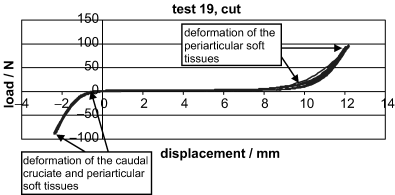
Example of a typical load–displacement curve generated for the cut CrCL.
The FTS: tibial crest is reportedly one of the most common extracapsular methods used to stabilize the CrCL-deficient stifle in dogs.37 It is based on Flo's modification of the retinacular imbrication technique.7 Usually a single lateral (and occasionally a medial) FTS is used. Isometric origin and insertion points may enhance function of the FTS: tibial crest.28 The placement of the tibial anchor at either the cranial or caudal prominence of the EG was tested at only one angle of flexion (135°) in our study; therefore, evaluation of isometric points for placement of the extracapsular sutures were not made. The FTS: caudal EG in this study resulted in extreme flexion of the joint, restricting stifle extension in every test. This was therefore not considered to be a functional suture placement position and may have affected the results; however, the order of treatments was randomized and should account for any variability. There was no significant difference in displacement or stiffness between the FTS: cranial EG and the FTS: tibial crest in any of the experiments in our study. However, only the function of the FTS: tibial crest in minimizing displacement was comparable with that of the intact CrCL in all 3 experiments. Figure 9 shows typical curves generated during testing of one stifle. The differences in stiffness and displacement are evident. The temperature at which the specimens was stored, −8°C, is not necessarily considered to be the ideal storage temperature for biological specimens; however, all specimens were stored at the same temperature and handled in the same manner and no problems were encountered (e.g., grafts tearing during manipulation) during the study. This, however, may have had an effect on the results.
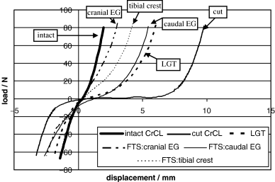
Examples of typical load–displacement curves generated for each treatment for one stifle.
Muscle groups that lend support to the stifle joint (extrinsic and intrinsic muscles) also play a role in the stability of the stifle. Inclusion or exclusion of these muscle groups during testing would have an effect on the results. It is difficult to postulate what that effect would be as we have found some difficulty in comparing the results of one study to another as different investigators eliminate or preserve different stabilizers of the stifle during testing.33,34
The results of our study indicate that a properly secured pedicle graft of fascia lata and the lateral one-third of the patellar ligament, with its base on the proximal tibia, confers translational stability in the CrCL-deficient stifle comparable with that of the intact CrCL in vitro. Also, the LGT was similar to the FTS in its ability to provide adequate stabilization of the CCL-deficient stifle in vitro. We also found that altering the placement of the tibial suture anchor point for the FTS to either the cranial or caudal prominence of the EG did not result in improved stiffness or enhanced stabilization of the CrCL-deficient stifle, and neither the LGT nor the FTS: tibial crest resulted in equal or greater stiffness than the intact CrCL.
The jig design allowed tibial rotation; however, another limitation of our study was the effect that this rotation had on translation. Also, differences in rotation between stabilization methods may also have had an effect on the recorded translation. This jig can be used in further studies to further assess the tibial rotation and to specifically address the potential effects of rotation on translation. The jig design allows for unrestricted movement of the tibia as shown in this study or the tibia can be fixed in position (by locking the tibial plates and cylinder and preventing any tibial movement other than translation). Another study specifically designed to assess the effect of the LGT on range of motion and flexion would also be of benefit.
Although there are limitations to our study, we believe that the LGT is a simple and effective technique for stabilization of the CrCL-deficient stifle. The LGT possesses some of the properties of an ideal material for stabilization of the canine cadaver stifle therefore a clinical study to determine the effectiveness of the graft in dogs is recommended.
Acknowledgments
The authors thank Terry Dew, DVM, MS, Diplomate ACVS, and Simon Roe, BVSc, PhD, Diplomate ACVS for their assistance with this study, as well as Terry Lawrence for the drawings. All equipment for the Securos 80 lb. Cranial Cruciate Ligament Repair System™ was supplied by Securos Inc. The authors would also like to thank Daryl Link, George Lough, Dave Simmons, and Robert A. Simonds from the Department of Engineering Science and Mechanics, V.P.I. and S.U., for their help in the design and construction of the testing jig and technical assistance during testing, as well as Pam Arnold, Chris Cohen, and John Strauss.


