Consideration of the transient material behavior under variable amplitude loading in the fatigue assessment of nodular cast iron using the strain-life approach
Funding information: German Federal Ministry of Economics Affairs and Energy (BMWi), Grant/Award Number: 0325707
Abstract
The consideration of realistic load assumptions is important for the fatigue design of highly stressed nodular cast iron components for wind energy application. Especially in case of overloads causing elastic–plastic deformation, residual stresses may have a strong impact on fatigue life. In strain-controlled fatigue tests with constant and variable amplitudes, the influence of overloads on lifetime was investigated. During fatigue testing, the transient material behavior, cyclic hardening, cyclic relaxation of the residual stresses, and quasi-static creep effects of the EN-GJS-400-18-LT was recorded and evaluated. To quantify the influence of the transient material behavior on the calculated lifetime, fatigue analyses are carried out with the strain-life approach, both with and without consideration of the transient material behavior. The results show that conservative damage sums are derived if the transient material behavior, especially the relaxation of tensile residual stresses, is neglected.
1 INTRODUCTION
Nodular cast iron components are often used in the wind energy sector due to their high design freedom and high load capacity. Highly stressed components, such as the rotor hub or the main frame, are typically made of nodular cast iron (GJS).
Due to stochastic wind loads,1 variable amplitude loads are used for the fatigue assessment. Numerous fatigue approaches are available for the assessment of components.2
In industrial application, guidelines with stress-based approaches are frequently used.3, 4 These consider influences due to, for example, stress gradients (microstructural support effects), surface roughness, or temperature. The loads are usually represented by a load spectrum transformed to a load ratio of R = − 1 by a given mean stress sensitivity. In this way, a fatigue assessment can be quickly performed for complex parts with variable amplitude loading. But, due to the assumed linear-elastic material behavior, sequence effects are not taken into account.
However, high operating loads or overloads, for example, caused by storms or grid losses, which lead to plastic deformation of the material and thus to residual stresses, cannot be evaluated directly with stress-life approaches. Furthermore, stress-based approaches do not take sequence effects into account. Subsequently, no changes of residual stresses due to, for example, exceedance of the yield stress can be considered. In addition, the stress-life approaches generally only cover the high cycle fatigue range (N > 104) and cannot assess damage components for overload cycles in the low cycle fatigue (LCF) regime.
The strain-life approach, as described, for example, Dowling5 or in the FKM guideline,6 can be applied in an acceptable calculation time to evaluate the fatigue life for crack initiation. It uses the cyclically stabilized material behavior and does not consider transient effects, for example, creep or cyclic mean stress relaxation. However, it can consider changes of the residual stresses due to exceedance of the yield stress and also allows the evaluation of load cycles in the LCF regime. Subsequently, the strain-life approach has been often used to evaluate the fatigue strength of components with overloads in the load spectrum.
The fatigue strength of welded joints with tensile overloads was analyzed in various publication.7, 8 The applied overload leads to compressive residual stresses in the fatigue critical weld toe notch and subsequently to an increase in fatigue life. With the strain-life approach, the beneficial effects could be quantified. However, if an overload is applied that leads to tensile residual stresses in the fatigue critical locations, harmful effects need to be considered. The fatigue strength of case-hardened specimens in strain-controlled tests was investigated.9 Due to periodic compressive overloads, the endurable strain amplitudes are significantly lowered due to the relaxation of compressive residual stresses.
Besides the influence of the overload on the crack initiation life, the residual stress state has also an influence on the crack propagation life. Tensile residual stresses lead to an accelerated crack propagation, compressive one to a retardation of the crack growth.7, 10
Independent from the sign of the residual stresses, that is, high tensile or high compressive ones, these can partially be reduced by the subsequent load cycles. This can be explained on one hand by an exceedance of the yield stress as it is covered by the strain-life approach. On the other hand, the residual stresses can be changed by a cyclic mean stress relaxation11 or static creep.12 With material models,13 these transient effects can be partially described. Due to their complexity and computing time, however, they are seldomly used in industrial application.
In cast iron, process-related material defects often cannot be avoided. The influence of those defects on fatigue strength of nodular cast iron is investigated.14-20 In this paper, the focus of the investigations is to determine the influence of the transient material behavior on the calculated damage sum. The influence of defects on fatigue properties was not investigated in this work; therefore, specimens containing major discontinuities were not considered in the evaluation. Moreover, large castings are not easy to be inspected with non-destructive testing during the production process. Especially shrinkages with size of 1 mm or less cannot be detected when looking at components with wall-thicknesses over 200 mm. In this case, the material has to be treated as sound even so smaller defects might be present. All defects still occurring less than 1 mm are within the scatter band and need to be taken as “as cast.” More detailed information on the microstructure of the specimens is presented in another publication.21
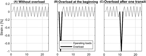
In this work, the influence of the transient material behavior on the calculated lifetime is investigated. For this purpose, strain-controlled fatigue tests and fatigue analyses with the strain-life approach were carried out. The specimens for the strain controlled fatigue test were taken from a machine frame of a wind energy turbine and tested under constant and variable amplitude loading.21 To investigate the influence of overloads on lifetime, three different scenarios were investigated: (a) without overload, (b) with an overload at the beginning, and (c) with an overload after one transit of the load spectrum (LS = 5 · 105). The overload consists of a cycle in the compression range (Δε = 1%, Rε = − ∞) and was selected in such a way that it leads to high tensile residual stresses.
2 FATIGUE TESTS
2.1 Specimen for the fatigue test
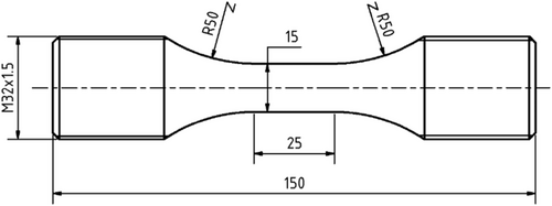
For the fatigue tests, unnotched specimens of EN-GJS-400-18-LT were used, which were taken from a main frame of a wind turbine. The position of the main frame where the specimens have been taken had a wall thickness of approx. t = 85 mm. In the test volume, the specimens have a diameter of d = 15 mm and a length of l = 25 mm (Figure 1). The highly stressed volume22, 23 of the specimen is HBV90% = 6.122 mm3. It should be noted that HBV90% is not only in the test volume but also extends into the transition radius. The chemical composition is shown in Table 1. Static tests showed a tensile strength Rm = 363.2 MPa, a yield strength Rp0.2 = 225 MPa, and a breaking strain of A5 = 26.6%. Metallurgical investigations21 showed a nodularity of 85.3 and a fraction of ferrite/pearlite/graphite of 82.2/4.6/13.3. Additional information is given in another publication.20
| C | Si | Mn | P | S | Mg | Cu | Ni |
|---|---|---|---|---|---|---|---|
| 3.75 | 2.16 | 0.21 | 0.022 | 0.005 | 0.041 | 0.010 | 0.02 |
2.2 Fatigue test under constant amplitude loading
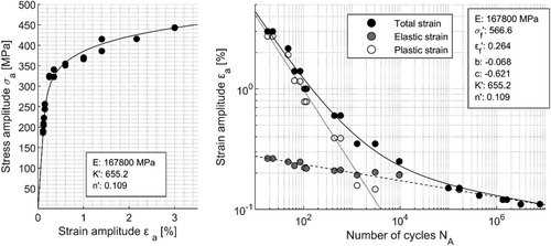
The strain controlled tests were carried out at room temperature on a servo-hydraulic test rig with test frequencies between f = 0.1 and 20 Hz and a strain ratio of Rε = − 1 in orientation to ISO 12106.24 The first 10 load cycles were always performed at a frequency f = 0.1 Hz. Then, in order to reduce the test duration, the frequency was increased as a function of the load levels. The tests were run until crack initiation. The crack initiation was detected by a stiffness decrease of the specimen. Based on the measured strain and the force on the specimen, a decrease of stiffness of 20% related to the initial state was used to detect the crack initiation. During the tests, the forces resp. nominal stresses were continuously recorded with a rate of 200 data points per cycle.
 (1)
(1) (2)
(2) (3)
(3) (4)
(4)
| Material | E (MPa) | σf′ (MPa) | εf′ | b | c | K’ | n’ |
|---|---|---|---|---|---|---|---|
| EN-GJS-400-18-LT | 167,800 | 567 | 0.264 | −0.068 | −0.621 | 655.2 | 0.109 |
 (5)
(5)
2.3 Fatigue test under variable amplitude loading
The fatigue tests with variable strain amplitude were performed on the same servo-hydraulic test rig as those with constant strain amplitudes. In order to use realistic loads in the investigations, a load spectrum derived from a wind turbine21 was used that corresponds to a life of 20 years and has a strain ratio of Rε = − 1.
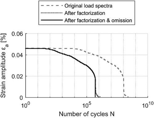
In order to obtain a suitable load-time history for the fatigue tests, the load spectrum is reduced from LS = 2.8 · 108 cycles to LS = 5 · 105 cycles by means of factorization and omission (Figure 5). This is necessary because the load-time history should be run through several times in Gaßner tests.31
- without overload
- with an overload at the beginning
- with an overload after one transit, that is, after LS = 5 · 105 cycles
The Gaßner-curves show a partially significant influence of the overload on the fatigue life (Figure 7). This is highest at low strain amplitudes since the residual stresses due to the overload are not reduced due to the subsequent load cycles. The local yield stress is never exceeded. At high strain amplitudes, the influence of the overload decreases since a partly relaxation of the residual stresses occurs. This leads to different slopes of the Gaßner-curves and a coincidence of the curves at about N = 5 · 105 cycles. This is caused by a reduction of the residual stress at high strain levels. In the Gaßner-curves, following number of tests could be considered in the evaluation: without overload: 6, overload at the beginning: 12, and overload after one transit: 10.

2.4 Changes in the local mean respectively residual stresses
- cyclic relaxation of local mean stress
- static creep
- change of local mean stress by exceeding the yield limit
- Cyclic relaxation is defined as decrease in the residual stress state (local mean stress) under constant strain-controlled testing11 (εm ≠ 0).
- Static creep is defined as an increase in plastic elongation at constant stress (σm ≠ 0). This effect can also be identified for an EN-GJS-400-15.12
- Residual stress reduction by exceeding the yield limit means that if the yield limit is exceeded, the residual stresses can be reduced or, depending on the load level, built up in the opposite direction.32, 33

All effects are addressed when loading with significant plastic strains and a stress ratio of R ≠ − 1. The significance of the individual influences depends on the load-time-history.
3 FATIGUE ANALYSIS
3.1 Applied fatigue assessment approaches
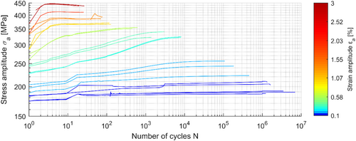
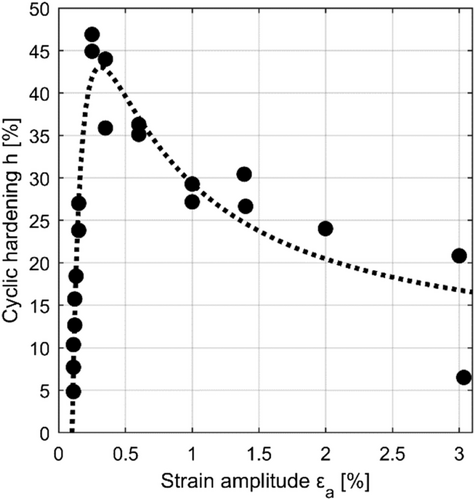
When the strain-life approach is applied in industrial application, no transient material behavior is generally used in the fatigue assessment. Effects such as cyclic hardening or cyclic mean stress relaxation are not considered. A cyclically stabilized stress–strain behavior over the entire component lifetime is usually assumed. As it can be seen in Figure 3, the EN-GJS-400-18-LT, however, shows a load-dependent hardening. A stabilization of the stresses at a constant strain level does not take place. The hardening takes place continuously until failure.
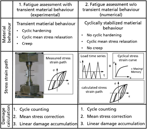
To investigate the influence of the transient material behavior on the damage sum, two different damage calculations are carried out for the fatigue tests with variable amplitude loading (Figure 9). Input data for both approaches are the recorded strain-time course from the fatigue tests and the strain-life curve from the constant amplitude fatigue tests. In the first variant, the fatigue assessment is considering the transient material behavior, and the recorded stress amplitudes have been used. Subsequently, all transient effects are covered. This variant is referred to as the experimental variant in the following. In the second variant, the fatigue assessment is carried out without consideration of transient material effects, and the stress amplitudes were numerically derived based on the cyclically stabilized material behavior. This approach is common and often used when elastic–plastic stresses have to be evaluated, and it is referred to as the numerical variant in the following.
 (6)
(6) (7)
(7)Next to PSWT and PB, there exist numerous other damage parameters, such as PJ.6 However, these are more complex in their application and not widely used in industrial application.
In order to visualize the influence of the mean stress sensitivity within the PB parameter, stress amplitudes were adjusted to derive constant PB-values at different mean stresses. Figure 10 shows examples of stress amplitudes and mean stresses for four different PB-values. It can be observed that the slope of the curves at high mean tensile stresses is flatter at low PB-values than at high ones. This means that the mean stress sensitivity depends on the load level.
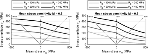
The linear damage accumulation according Palmgren37 and Miner38 was used to calculate the damage sum. The two fatigue assessments differ only with regard to the stress behavior that occurs due to the measured strain-time history in the fatigue test.
3.2 Derived stresses for fatigue assessments
In the experimental variant, the transient material behavior is taken into account in the fatigue assessment. For this purpose, the actual strain from the extensometer and the actual force were recorded during the Gaßner tests. Based on the force, the nominal stress was calculated. Thus, no model of the stress–strain behavior was necessary in the damage calculation since the real measured time-dependent stress–strain behavior was used. This includes cyclic hardening, cyclic mean stress relaxation, and creep.
In the numerical variant, the corresponding stress is calculated on the basis of the actual strain with the cyclically stabilized material behavior and the Masing-Memory model.32, 33 The Masing-Memory model considers the shift of residual stresses caused by exceeding the yield stress, but does not consider cyclic hardening, cyclic mean stress relaxation, or creep.
The two variants are based on the identical strain-time history; only the underlying stress history is different due to the material behavior. A comparison of the stress curves is shown in Figure 11. In the scenario without overload, a deviation of the maximum stress can be seen at the beginning of the test. This is due to the not yet cyclically hardened stress–strain behavior of the transient material behavior. In the further course the deviations of the stresses are small but constant.
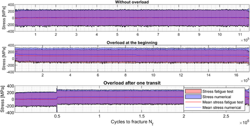
The compressive overload lead to measured residual stresses of σres,exp = 260 MPa and calculated residual stresses of σres,num = 320 MPa, independent of the time at which the overload occurs. These residual stresses were reduced by the following loads: in the scenario with overload at the beginning, the calculated stresses are significantly higher than the stresses derived based on the transient material behavior (σm,exp = 68 MPa vs. σm,num = 103 MPa). In the scenario with overload after one transit, the calculated mean stresses are also higher than the measured ones (σm,exp = 49 MPa vs. σm,num = 67 MPa).
In the second variant with numerically derived stresses, the resulting residual stresses due to the overload should be independent of the time they occur. At the beginning, it should lead to identical residual stresses as after one transit, because every time the same cyclically stabilized stress–strain behavior is used. In Figure 11, however, it can be observed that the calculated mean stresses differ (σm,num,start = 103 MPa vs. σm,num,transit = 67 MPa). These differences are due to control inaccuracy in the fatigue test (it should be noted that in both variants the measured strains from the fatigue test were used for the fatigue assessments). In the scenario with the overload after one transit, an overshoot of the controlled strains occurred directly after the overload, which led to a reduction of the tensile residual stresses. This is shown in Figure 12. So a direct comparison between the residual stresses for both scenarios, overload at the beginning and overload after one transit, cannot be performed, even for nominal identical strain amplitude levels. However, for the comparison of the impact of the transient material behavior, it is not necessary that the mean stresses are exactly the same because the fatigue assessments are evaluated with regard to their damage sum and the damage sum takes the mean stress into account.
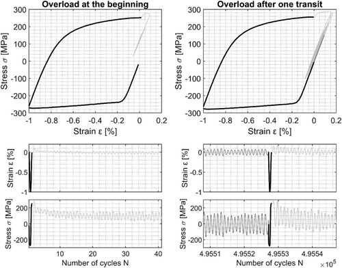
In Figure 12, a jump in the stress after the overload cycles can be observed. This is due to the fact that the overload cycle was run with a very low test frequency (f = 0.01 Hz). At this low frequency, creep effects are already visible, which can be seen in a reduction of the maximum stress. The following load cycles are performed with a higher frequency (f = 8 − 20 Hz) and show a clear increase of the maximum stress. The variation of the test frequency was performed to find a compromise between test duration and control accuracy. The test frequency was varied in a range where no significant influence was expected. However, Figure 3 and Figure 12 show an influence. Though there is no significant influence on the main findings, since the same test frequencies were used for all scenarios, they are again comparable.
3.3 Results of the fatigue assessments
In the damage accumulation, higher mean stresses lead to higher damage fractions due to the mean stress sensitivity of the material. In the calculations, the influence of the mean stresses on the fatigue damage are assessed in the damage parameter according to Bergmann and are weighted with the parameter k.
Since the mean stresses in the experimental variant are lower than in the numerical variant, the damage sums in the numerical variant are higher than those determined with transient material behavior (Figure 13). With increasing deviation of the mean stress between both variants, the deviation in the damage sums also increases. This is caused by a high mean stress sensitivity. Figure 14 shows that with increasing mean stress sensitivity, the damage sums of the different overload scenarios also deviate from each other. This indicates that a mean stress sensitivity of M = 0.3 represents the different overload scenarios best, because there the smallest deviations between the damage sums of the overload scenarios are archived. The damage sum is not strongly depending on the mean stress or the occurrence of an overload; all fatigue tests fail at almost the same damage sum.
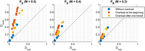
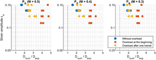
The calculated damage sums are in both cases clearly below the theoretical damage sum of D = 1, even if the transient material behavior with the measured stress amplitudes and mean stresses from the fatigue tests are taken into account (Figure 13). A dependence of the load level on the damage sum could not be determined (Figure 14).
The derived damage sums are depending on the overload scenario and the mean stress sensitivity. In the numerical variant, the average damage sums lie between D = 0.2 (without overload) and D = 0.6 (overload at the beginning with a mean stress sensitivity of M = 0.5). In the transient variant, the average damage sum lies between D = 0.06 (without overload) and D = 0.2 (overload after one transit with a mean stress sensitivity of M = 0.5). In literature, allowable damage sums for nodular cast iron vary. Most recommendations39-41 are between D = 0.2 and D = 0.5; however, recommendations4 are also given with D = 1.
4 SUMMARY AND CONCLUSIONS
- The conventional damage calculation with a simplified material behavior (w/o transient effects) leading to damage sums of about D = 0.2 matches to the damage sums which can be found in literature
- The conventional damage calculation with a simplified material behavior (w/o transient effects) can be used to archive reliable results even if the materials show significant cyclic hardening and mean stress relaxation like EN-GJS-400 U-LT
- The conventional damage calculation with a simplified material behavior (w/o transient effects) leads to damage sums which are by a factor of 3 higher than those calculated by means of real transient material behavior. Therefore, it is important not to mix the variants. The determined endurable damage sum is always connected to the evaluation approach (e.g., transient or stabilized material behavior, damage parameter, and mean stress sensitivity). A combination of different approaches or boundary conditions may lead to non-conservative results.
- A mean stress sensitivity of M = 0.3 represents the different overload scenarios best. The damage of the overload is essentially caused by the resulting tensile residual stresses.
- High load peaks within the load spectrum can lead to a reduction of the residual stresses, which is why the influence of the overload at high loads is lower than at lower load collectives.
- The use of a realistic transient material behavior does not necessarily lead to the theoretical damage sum of Dth = 1.
ACKNOWLEDGMENTS
The results presented in this paper were derived in the project “GaßnerWind.” The authors thank the German Federal Ministry of Economics Affairs and Energy (BMWi) under the grant “0325707” for funding this project and the companies supporting the investigations.
Open Access funding enabled and organized by Projekt DEAL
NOMENCLATURE
-
- c
-
- fatigue ductility exponent
-
- b
-
- fatigue strength exponent
-
- f
-
- frequency
-
- h
-
- cyclic hardening
-
- k
-
- mean stress parameter
-
- n
-
- cyclic hardening exponent
-
- t
-
- time
-
- E
-
- Young's modulus
-
- K′
-
- cyclic hardening coefficient
-
- HBV90%
-
- highly stressed volume 90%
-
- Ls
-
- spectrum length
-
- M
-
- mean stress sensitivity
-
- N
-
- number of cycles
-
- Ni
-
- number of cycles to crack initiation
-
- PB
-
- damage parameter according to Bergmann
-
- Rε
-
- strain ratio
-
- ε
-
- strain
-
- εa
-
- strain amplitude
-
- εa,e
-
- elastic strain amplitude
-
- εa,p
-
- plastic strain amplitude
-
- ε′f
-
- fatigue ductility exponent
-
- Δε
-
- strain range
-
- σ
-
- stress
-
- σa
-
- stress amplitude
-
- σm
-
- mean stress
-
- σ′f
-
- fatigue strength coefficient
Open Research
DATA AVAILABILITY STATEMENT
Data is available on request from the authors.


