Use of the universal scan template to achieve a predictable optical impression: Preliminary data of a case series study in complete edentulous patients
Abstract
Background
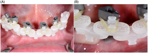
Full-arch IOS scan of edentulous areas rehabilitated with dental implants is nowadays still described as an unpredictable procedure. To improve the accuracy, a universal scan template (UST®) is proposed in this article. The clinician can easily assemble the template with a mechanical coupling, by matching the scan bodies with objects of known dimension characterized by specific markers. The UST® facilitates the scanning of an entire arch on scan bodies, reducing the learning curve, simplifying acquisition movements, shortening the scanning time, and drastically reducing the risk of distortions and aberrations of the scans.
Materials and Methods
In a case series study on 12 patients, the improvement in the accuracy of the scans with UST® was validated by comparing the STL files derived from scans with and without the guide in place. A titanium bar was produced from each optical impression.
Results
The bars obtained from the optical impressions taken without UST® were found to be nonpassive in the mouth in the majority of the cases. On the contrary with the use of UST® we obtained 12 passive prosthetic rehabilitations.
Conclusions
The proposed solution may represent a valid method to improve the predictability of full arch optical impressions on implants.
Summary Box
What is known
A recent systematic review suggested that, based on the results of the included studies, full-arch digital implant impressions taken using intraoral scanners are still not sufficiently accurate for clinical application.
What this study adds
This study introduces a clinical tool to overcome the issue and suggests that full-arch digital implant impressions taken using intraoral scanners can be sufficiently accurate nowadays.
1 INTRODUCTION
An accurate optical impression of the entire edentulous arch rehabilitated with dental implants is today still described in the literature as a problematic and unpredictable procedure.1-10 A recent systematic review highlighted how IOSs do not provide accurate complete-arch digital impressions in cases with implants. It also reported how the accuracy of IOSs for complete arches can differ under various clinical scenarios and depending on the different type of IOSs.11 To avoid this lack of accuracy of IOSs is important to inform the clinician about the use of different techniques such as photogrammetry that has been shown to be a predictable impression technique in full arch cases. The issues related to the IOS full arch impression on implants are mainly due to the absence of characterized and stable surfaces such as natural teeth and to the fewer number of reliable reference points that can be used during the impression phase and the subsequent dental technician phases. The inter-implant distance, especially in the absence of keratinized tissue, appears to play a key role in achieving an accurate full arch scan on implants.12 Despite these aspects, an accurate scan of the edentulous arch and of the position of the dental implants can be a fundamental and essential starting point to obtain a final passive prosthetic rehabilitation of implants. Providing a solution to overcome these problems is today a clinical need. Solving this issue is fundamental for the dentist who wants to follow a full digital flow of an entire edentulous arch on implants. In literature different solutions have been proposed to overcome the issues regarding full arch digital impressions on implants. During the acquisition with an IOS, for example, have been proposed the application of a pressure-indicating paste or artificial landmarks on the edentulous area,13, 14 the positioning in between the scan bodies of an auxiliary geometry part reproducing dental anatomy or a geometric point of reference,12, 15-18 the use of a particular scan body geometry with a lateral flag,19 and the splinting of scan bodies with thermoplastic resin or a dental floss are some of the clinical solutions proposed to provide a well-visible scanning route for the IOS devices.20, 21 Garcìa-Martinez et al. proposed the introduction of customized over scan body rings as an auxiliary system to increase the scanning efficiency.22 An alternative to the acquisition with an IOS is the photogrammetry that has been demonstrated as a predictable impression technique in complete edentulous patients.6-10 A recent systematic review has shown that intraoral scanning and photogrammetric method showed comparable accuracy for registering implant positions in the full-arch edentulous cases. However a tolerable implant prosthesis misfit threshold and objective misfit assessment criteria (for linear and angular deviations) should be verified in clinical studies.23 Accordingly other authors reported the same results, describing photogrammetry as a reliable alternative for acquiring implant position.24
- the clinical passivity of the full arch titanium bar manufactured starting from an optical impression with the use of the Universal Scan Template (UST®);
- the scan time with and without UST® in place.
2 MATERIALS AND METHODS
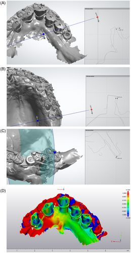
- Isolation of areas of interest, selecting the surface of all the scanbodies from the two STL files and the most stable, easily identifiable and morphologically characterized areas of the soft tissues. The purpose is to use only the selected areas for performing the alignment. These areas represent also an important support in the analysis and evaluation of any arch distortion.
- Selection of three common points on both files to simplify the first phase of the alignment before the use of the best fit algorithm. This algorithm, then finds the best possible alignment starting from the three points and considering only the selected surfaces.


| No. of cases | No. of implants | Upper/lower jaw | Scan times with UST® | Without UST® | Mean distortion and standard deviation (mm) between scans with and without UST® |
|---|---|---|---|---|---|
| 1 | 4 | Lower | 1′26″ | 9′25″ | 0.84 ± 0.09 |
| 2 | 6 | Upper | 1′48″ | 7′15″ | 0.79 ± 0.11 |
| 3 | 5 | Lower | 2′64″ | 6′35″ | 0.39 ± 0.03 |
| 4 | 4 | Upper | 1′82″ | 5′24″ | 1.91 ± 0.05 |
| 5 | 4 | Lower | 2′42″ | 4′89″ | 1.48 ± 0.11 |
| 6 | 6 | Upper | 1′67″ | 4′35″ | 0.68 ± 0.14 |
| 7 | 5 | Lower | 3′92″ | 6′24″ | 0.29 ± 0.04 |
| 8 | 6 | Upper | 2′78″ | 5′12″ | 0.40 ± 0.02 |
| 9 | 4 | Lower | 3′16″ | Not possible | Comparison not possible |
| 10 | 5 | Lower | 2′17″ | Not possible | Comparison not possible |
| 11 | 6 | Upper | 1′56″ | 3′72″ | 0.015 ± 0.01 |
| 12 | 6 | Upper | 2′34″ | 4′35″ | 0.008 ± 0.01 |
A measure of the distortion between the two scans present at the level of the most distal scan bodies was acquired for each case (Table 1). A bar was then produced from each pair of scans for each case. Bars are all produced by the same producer (LaStruttura Digital Dentistry Solutions, Cassano Magnago, Italy) in grade 5 biomedical titanium (BEGO GmbH & Co.). The bars are all produced through a milling process, made with Mikron HSM 400 (GF Machining Solutions).
- Periapical x-rays of any implant to verify the absence of gap between the implant fixture and the bar.
- Sheffield test: in order to perform this test, the bar has been inserted over the supporting implants. Then the most distal retaining screw has been tightened and the rest of the retaining screws have been kept out. If a gap appears between the remaining supporting implants and the bar, it indicates that the superstructure does not fit passively.26
A statistical analysis was performed using GraphPad Prism 5.03 (GraphPad Software, Inc., La Jolla, CA) both for the timing comparison and for the distortion between the two scans. In particular it was applied a Student's t test for paired data, after verifying the normality of distributions using the D'Agostino & Pearsons omnibus normality test.
3 RESULTS
As concern the statistical analysis, the timing comparison made with the student's t test for paired data, after verifying the normality of distributions using the D'Agostino & Pearsons omnibus normality test, revealed a highly significant result, with a value of p = 0.0004. The distortion between STL files was verified with the same t-test for paired data, confronting with zero (absence of distortion), after verifying the normality of the distribution first, and it was revealed also in this case a significant value of p = 0.0052, so there is a significant distortion between the STL analyzed with and without UST® in place. Post hoc power analysis was performed using an online tool (https://clincalc.com/stats/Power.aspx), based on the mean distortion and standard deviation (one-sample, continuous endpoint), and it was found a power of 87.4% for a double-sided test, indicating that the sample was sufficient to detect the observed difference.
The results of the preliminary study regarding the scanning times and the average distortion between the two optical impressions (with and without UST®) are summarized in Table 1. Specifically, in two cases out of 12 (both in lower arch) it was not entirely possible to achieve the scan without the use of UST®. In other 10 cases the scan was possible both with and without UST® generating a pair of STL files each. Each pair (with and without UST®) was superimposed and analyzed thanks to a Best Fit Align process present in the CAD software (3shape Dental System). The distortion values were measured through a 2D section at the level of the two most distal scan bodies of each clinical case (Figure 3A–C). Only 2 out of 10 cases revealed minimal distortions between the optical impression with UST® and the one without (close to 0.010 mm). On the other hand, in eight cases (four of which in the upper arch and four in the lower arch) there was a substantial difference (up to a value of 1.964 mm) between the scan with UST® and without UST®. Regarding the first two cases with minor distortions, the bars produced from scans with and without UST® proved to be passive in the oral cavity. But concerning the other eight cases, the bars produced by the optical impression without UST® did not allow a passive tightening. On the contrary, considering the same cases, the bars made from STLs with UST® in place turned out to be passive. So, bars produced from the optical impressions without UST® were found to be nonpassive in eight out of 10 cases, when screwed onto implants in the oral cavity. In contrast, all the 12 bars produced from the STL with the UST® in place had a passive fit when screwed in the oral cavity (Table 2).


| With UST® | Without UST® | |
|---|---|---|
| Number of scans | 12 | 12 |
| Cases excluded from the study (due to the impossibility to acquire the scan) | 0 | 2 |
| Number of bars produced | 12 | 10 |
| Number of passive bars | 12 | 2 |
| Percentage of passive bars | 100% | 20% |
4 DISCUSSION
The growing spread of digital dentistry has led to a greater knowledge of its potential, as well as its limits. One of these is the difficulty in acquiring an accurate optical impression of the entire edentulous arch rehabilitated with dental implants. This issue is above all frequent in those areas where there is a deficit of stable anatomic landmarks and surfaces that can be easily acquired by the intraoral scanner. To overcome these problems, the UST® was introduced. The results obtained in this study show how the lower jaw is particularly critical for a correct acquisition, with distortion values between the two impressions greater than values in the upper jaw. In two clinical cases it was not even possible to complete the scan of the lower jaw. The upper arch, characterized by a wider presence of landmarks (palatine wrinkles, more stable keratinized mucosa, etc.) is less problematic, but not free from distortions between the two impressions acquired with and without UST®. In addition, the four operators who took optical impressions with UST® reported several advantages, summarized in Table 3. These advantages, related for example to the timing of the acquisition (on average reduced with the use of UST®) can represent an important help for the clinician in the various steps of an implant prosthetic rehabilitation.
| Most frequent issues detachable during scans without UST® | Advantages resulting from the use of the UST® |
|---|---|
| (1) Long scanning times (see Table 1) or the impossibility, in some cases, of completely acquiring the scan of the edentulous arch (in two cases out of 12). | (1) Reduction of data acquisition times (average of about 2 min) and scan acquired without problems in all cases analyzed. |
| (2) The need to interrupt and resume the scan several times due to the lack of landmarks in the edentulous arch, as well as due to the presence of mobile points (free mucosa) not recognizable by the intraoral scanner once the scan has been resumed. | (2) Increased scanning continuity during data acquisition without multiple interruptions. This guarantees a reduction in the number of patches obtained up to the possibility of having a single continuous scanning flow. |
| (3) Increased data processing time during the postprocessing phase following acquisition, due to the high number of patches resulting from the interruptions. | (3) The reduction of patches minimize the intervention of the software algorithm in the data optimization phase. |
| (4) Difficulty finding a reliable landmark to restart scanning when stopped. | (4) UST® represents a stable reference point during data acquisition, allowing to easily restart from it. This represents a valid aid for the clinician. |
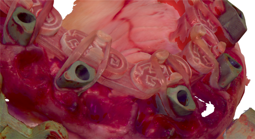
| (5) Difficulty in data acquisition in the case of surgical flaps, edematous tissues and intra-operative situations characterized by the lack of stable and reliable reference points during scanning. | (5) UST® allows to obtain an accurate impression even in the case of immediate load rehabilitations with open flaps or postsurgical edematous tissues (Figure 4). |
| (6) In presence of free mucosa or edentulous areas, the acquisition becomes difficult due to the lack of landmarks. | (6) In conditions of maximum tissue atrophy, and in the presence of free mucosa without stable keratinized tissue, UST® allows an easier acquisition. |
| (7) Creation of distortions that compromise the accuracy of the arch and make it difficult or impossible to acquire the entire arch. | (7) The use of the UST®, providing a stable and immutable reference. This reduces the risk of distortions and inaccuracies that occur when the software has to combine patches that are different one from each other, even if acquired in the same position because the tissue changed during the acquisition. |
As described in the introduction section, various techniques and solutions have been proposed in literature to overcome the issues related to a full arch digital implant impression. Between them the application of a pressure-indicating paste or artificial landmarks on the edentulous area,13, 14 the positioning in between the scan bodies of an auxiliary geometry part reproducing dental anatomy or geometric point of reference,12, 15-18 the use of a particular scan body geometry with a lateral flag19 and the splinting of scan bodies with thermoplastic resin or a dental floss are some of the clinical solutions proposed to provide a well visible scanning route for the IOS devices.20, 21 Regarding the application of a pressure indicating paste or artificial landmarks it is important to report that these markers can be removed or a movement can occur during the acquisition, compromising it. As concern the positioning in between the scan bodies of an auxiliary geometric part reproducing the dental anatomy, it can represent a valid method, but it is also important to notice that these techniques require a further digital scan of just the scan bodies in place in order to project the device that can be used in a second scanning phase. On the contrary, UST® is modular and does not require a preliminary scan of the scan bodies in place and a specific CAD project of the scanning device for each single case. In fact, it can be assembled chair-side, directly by the clinician, on the day of the scan combining the various units. These units can be used indiscriminately for each clinical case regardless of the shape of the dental arch and the type of implants connections. In this way, a personalized CAD design of the auxiliary scanning device is not necessary for each clinical case as it happens for other scan templates reported by other authors.12, 15-18 Again, the scan body with a lateral flag proposed by Huang et al. can represent a valid method, but it can be challenging in case of implants with important relative angulations.19 In fact, being the lateral flag rigid, it can represent and obstacle to the correct insertion of the scan body on the implant fixture if more implants are present and with different angulations. The splinting technique proposed by Retana et al. can help the IOS during the acquisition, but it requires a customized splinting specific for each case and so some clinical time for its preparation before the scan phase.20 A recent in vitro study27 showed a significant improvement of the overall accuracy in a complete-arch implant digital impression with splinted scan bodies, particularly reducing linear and angular deviations at the most critical posterior implant positions. The study reports promising results supporting also the present article. As an improvement to the previous study, the same conclusions are lead, but in vivo and not in vitro.
In this study, through the use of UST®, 12 passive implant prosthetic rehabilitations on edentulous full arches were delivered. To evaluate the passivity of the bars, a Sheffield test was performed.26 Over the years, several methods have been proposed in literature for evaluating passive fit. In this study the fit accuracy can be first visually checked intraorally according to the Sheffield's test criteria.26 In this study, in order to perform this test, the bar has been inserted over the supporting implants. Then the most distal retaining screw has been tightened and the rest of the retaining screws have been kept out. If a gap appears between the remaining supporting implants and the bar, it indicates that the superstructure does not fit passively. Historically, Henry et al.28 suggested alternating finger pressure and perception of rocking motions. This consists of applying finger pressure on the end of the framework and then on the other end after placing the framework in position. Adell et al.29 suggested that this technique can be improved if saliva is present. It is considered misfit if rocking or saliva movement occurs. These techniques can be improved by use of magnification system. Also radiographs are a simple and important evaluation of the framework misfit. Again, the passivity was checked also from intraoral x-rays identifying any possible gap between the implant fixtures and the titanium bars. The passivity of the superstructures is a prerequisite for the long-term success of the implant-prosthetic rehabilitation.30
Concerning the type of scanner used, in this study we decided to choose Trios (3Shape, Trios4, Copenhagen, Denmark) among the different intraoral scanners present in the market. This because in the literature it seems to have the higher precision levels compared to other intraoral scanners.31
5 CONCLUSIONS
The results of this clinical study should be interpreted with caution due to the limited sample size. Nevertheless, the clinical use of UST® attached to scan bodies during an optical impression acquisition, made it possible to manufacture full arch bars with a passive fit. The scanning time was reduced. Further clinical studies are warranted to confirm these promising preliminary results.
AUTHOR CONTRIBUTIONS
The concept and design of this study was performed by Tiziano Testori. Data were collected by Veronica Campana, Andrea Papa, Manuel Amilcare Silvetti and Tiziano Testori. Data analysis and interpretation of data were performed by Massimo Del Fabbro and Tiziano Testori. Statistics was executed by Massimo del Fabbro. Writing and critical revision was performed by all authors.
CONFLICT OF INTEREST STATEMENT
The authors declare no conflict of interest.
INFORMED CONSENT STATEMENT
Informed consent was obtained from all subjects involved in the study.
Open Research
DATA AVAILABILITY STATEMENT
The data that support the findings of this study are available on request from the corresponding author. The data are not publicly available due to privacy or ethical restrictions.


