Cervicothoracic junction in disaster victim identification: Idiosyncrasies and relevance of body position for advanced chest radiograph comparisons
Abstract
Standard plain film medical radiographs often form a valuable line of evidence to identify individuals in large-scale fatality events. While commonly available, chest radiographs present a challenge that their analysis is somewhat more involved and complex than radiographic records of other body regions. For example, chest radiographs concern subtler morphological varieties of smaller anatomical features across a larger number of skeletal elements in contrast to frontal sinus comparisons that concern a large, (often) single, highly variable void within one bone. This does not detract from or discount chest radiographs as useful identification aids, but it does demand additional prerequisite skills in radiographic interpretation to ensure valid conclusions are attained. When subjects deviate from standardized antemortem (AM) radiographic positions and/or the image quality decreases, the complexity of a chest radiograph comparison is elevated. Generally, the current body of forensic radiographic comparison literature infrequently addresses these more complex circumstances. In this paper, we use real-world radiographic comparison reference images from a military DVI repatriation context to illustrate these factors and outline some procedures that enable these complexities to be easily recognized and appropriately addressed at case examination. A report for an exemplar case that concurrently highlights multiple factors is presented. For novices learning radiographic comparison methods, this case review saliently demonstrates: (1) why the AM reference radiograph(s) drive(s) the radiographic comparison procedure; (2) why care should be taken for correct positioning of the cervicothoracic junction in postmortem radiography of chest elements.
Highlights
- Antemortem chest radiographs are commonly available and can frequently assist DVI.
- The cervicothoracic junction is a useful region for analysis in these cases.
- Factors adding complexity (and methods to recognize them) are reviewed.
- A case with multiple complex factors acting concurrently is presented.
1 INTRODUCTION
When antemortem (AM) reference radiographs exist for persons suspected to be part of a mass fatality incident, postmortem (PM) radiographs can be taken and compared with the relevant AM images to assist identification [1-6]. Such radiographic comparisons extend beyond forensic odontological examinations of the teeth or dental restorations [7-9] to include the natural shape and form of the skeleton [10-12]. Concordant skeletal anatomy, between the AM/PM imaging sessions, is indicative of decedent identity, while discordant skeletal morphology is grounds for an exclusion [5, 11, 13]. It is especially important to note that exclusions can be of equal value to concordances, especially where the identification universe (subset of plausible possible matches from the population at large [14, 15]) is small and closed.
The radiographic comparison method is underpinned by the longstanding premise that, for skeletally mature individuals or individuals close to skeletal maturity, radiographic shape and densities of living bones are stable across substantial periods of time (e.g., 20+ yrs), as documented by repeated radiographs of the same skeletal elements of the same individuals [12, 16, 17]. It is also well-known that in all living adults the bone is not static, that is, approximately 5%–10% of the skeleton in any given year is actively undergoing bone matrix resorption followed by replacement at the cellular level [18, 19]. In healthy young-to-middle-aged adults, this process occurs without change in the macroscopic shape/size of whole bones, in a process termed bone turnover [20, 21]. Tight coupling between bone matrix resorption and replacement (by the same amount), produces the result that bones maintain their macroscopic structure (and integrity) in bone turnover until approximately 50 years of age [19]. After this time, age-related bone loss begins to accelerate, due to increased activity of osteoclasts, that may cause osteopenia/osteoporosis [19]. Here, it is worth noting that in females, trabecular bone loss is typically greater than cortical loss and, at the cortex, endosteal surface resorption is the primary driver of the observed cortical thinning [22]. So far, it has not been documented if these same observational patterns apply to males who are known to undergo age-related bone loss at slower rates than females [19, 22].
Part of the utility of radiographic comparison is that the method concerns the skeleton, which is resilient to destruction, and so the analysis can be conducted for intact decedents [2, 8, 23-27], burnt/fragmented bodies [1, 3, 11, 26, 28, 29], decomposed remains [30, 31], and/or fully skeletonized human remains [13, 32-37]. Radiographic comparisons can be made for any body region and a wide variety of examples have been previously published: for example, see for skull [38], vertebrae [13, 30], pelvis [39], clavicles [32-34], hands [11, 16, 25], knees [26, 40], and feet [27]. A major attribute that contributes to the utility of the method for identification, is the high frequency with which diagnostic radiographs are taken during life for medical purposes [5]. These features make radiographic comparison highly relevant to disaster victim identification [1, 3, 4, 29] in both civilian [5, 28, 41] and military contexts [32, 42, 43].
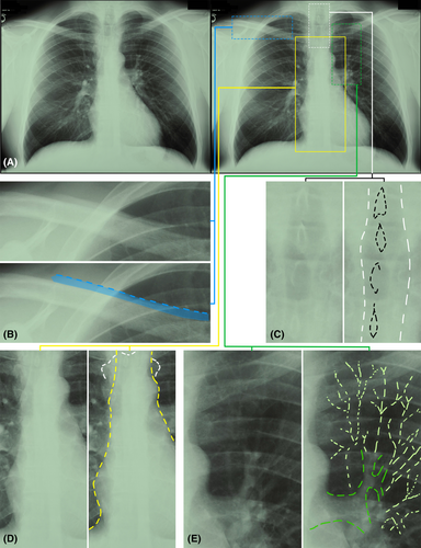
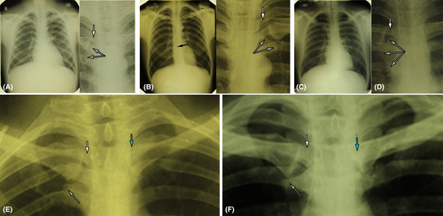
Chest radiographs are the most common type of radiograph taken for clinical examinations in medicine [44] and this too is reflected in the historical US military context where medical screening radiographs have been undertaken by the Army since 1935 and all forces since 1941, as a routine part of the military induction process [45, 46]. For chest radiograph comparisons, the cervicothoracic junction (C3-T3 vertebrae and clavicles) holds special utility because the neck vertebrae are subject to little hard tissue shielding [13, 23], the low density of the trachea permits good visibility of the shafts of the lower cervical and upper thoracic spinous processes in the neck, and the clavicles are readily evident due to their comparatively larger size and density (thick cortex) (Figure 1). In cases involving skeletonized remains, these bony elements can also be readily reassembled and positioned on the image receptor to simulate antemortem radiographic positions, as necessary for side-by-side comparisons and AM/PM image superimpositions [1, 5, 11, 13, 32].
The method's applicability by a subject's chronological age is highly context dependent and hinges most on: (1) the time interval between AM radiograph acquisition relative to time of death; (2) the status of the body-region-of-interest's closeness to skeletal maturity. The young adult skeleton is well-suited because it dually possesses fully expressed macroscopic features and provides the most tolerance for lengthy timeframes between AM radiograph acquisition and death. For hand radiographs, where growth plates are generally fused by 16 years of age (hand) or 20 years (wrist) [47], it has been reported that identification can be conducted from late adolescence through to the mid-thirties [16]. With regard to the cervicothoracic junction, vertebral epiphyses appear as young as 10 yrs and are fully closed around the same time as those for radiographs of the wrist or a little later: cervical vertebrae annular epiphyses by approximately 21 years and thoracic vertebrae 25+ years [47]. The clavicle is the first bone of the body to begin ossification (5–6 weeks of embryonic development), while its endochondral medial end is both the slowest and last to fuse (early-twenties) [47, 48].
In older subjects, for example, ≥50 years, osteoarthritic modifications such as lipping and spurs may be apparent (see above), and rather than being disadvantageous to the comparative process they can be facilitative if the AM and PM radiographs are taken within short intervening time periods such that the distinctive osteophytic changes are visible on both radiographic records (osteophytic growths are highly varied between individuals and distinctive). Where longer time frames between AM/PM radiographs may exist and are recognized, the highly focal changes of osteoarthritis and degenerative joint processes generally do not interfere with, or prevent, comparisons using more general (broader scope) features of the skeleton that remain static [12, 17]. For subadults, few systematic studies of method sensitivities and performance have been conducted, so application of methods to children are generally not recommended [16] and further studies in this area remain in need. For older adolescents, radiographic fields-of-view are broad enough that bones possessing different rates of formation are often present in the same radiograph. This provides examiners with the capability, in these cases, to rely most on those elements that are nearest to their terminal end stages of ossification.
As experts in skeletons, it is logical for forensic anthropologists to be frequently (and increasingly) called upon to conduct radiographic comparisons—these evaluations of course concern mapping of skeletal (dis)concordances between bones acquired on AM and PM radiographs [5]. For chest radiographs—which are primarily used for diagnosing thoracic lesions/disease in the first medical instance—image analysis for identifications is not necessarily straightforward. Rather, the challenges of reading 3D anatomy from 2D radiographs (with its combined effects of tissue shielding) has long been recognized [49, 50]. It is a necessity, for chest radiograph comparisons, that anthropologists are additionally proficient in reading soft tissues, so that they can correctly determine body position and bone tissue interfaces from a complex array of radiographic shadows. Below, we outline some of the complexities of chest radiographs and provide a worked example for an involved comparison.
While studies have shown that chest radiographs can be successfully compared in some identification tasks by novices who rely on black-and-white pattern matching without a detailed appreciation for the anatomical signal embedded in the radiographic images [51-54], accuracies for novices decline sharply when the viewing conditions are not ideal—for example, image clarity decreases or there is increased tissue shielding [52-54]. This again makes it highly pertinent that forensic analysts undertaking radiographic comparisons hold task-specific proficiency, since radiographs in real-world radiographic comparison cases rarely adhere to ideals. Where there is substantial departure from ideal imaging conditions or circumstances preventing straight-forward analysis (i.e., based only on gray scale pattern matching without deeper anatomical interpretation), we term these cases “advanced comparisons.” We include in the advanced category, comparisons that draw on image superimposition methods to demonstrate a match or no-match result, since these require the ability to read, in detail, the body position from the AM radiograph.
2 CHEST RADIOGRAPH COMPLEXITY FOR SKELETAL ANALYSIS
2.1 Tissue contrast factors
Unlike limb radiographs that are often taken for the clinical purpose to examine the skeleton, antemortem chest X-rays (see e.g., Figure 1) are almost always taken to investigate or show anatomical pathology of the soft tissues (pleura, lung, heart etc.) [55, 56]. Subsequently, they are not taken at settings that are optimized to view the bony skeleton, since the much less-dense soft tissues of the lungs are the focus of the examination and must be retained on the image [57, 58]. For example, the air-filled lungs require a relatively low X-ray energy/penetration power that, in turn, means the dense mediastinum is generally underexposed, yielding a bright region between the lungs that makes it difficult (and sometime impossible) to observe the sternum (Figure 1D). These exposure levels, that are not optimized for all bones, add a level of technicality to the chest radiograph comparison process from a skeletal or forensic anthropology perspective.
2.2 Soft tissue shielding factors
As the thorax is a large structure filled with multiple soft tissue organs that lay behind or in front of the skeleton, the radiograph comparison analyst must not only be able to differentiate soft-to-soft tissue and soft-to-hard tissue interfaces in the same region, but they must be additionally able to differentiate superimposed densities that overlay one another. At first glance this might seem like a simple task, however, there are regions of the chest, such as the mediastinum, where multiple structures are packed close together that make differentiation challenging. This applies at the medial clavicle ends where, for example, tracheal stripes (lateral walls of the trachea), paraspinal lines (soft tissue running immediately over and beside the vertebral column), and posterior junction line (meeting of the left and right pleura posterior to the esophagus, but anterior to the thoracic vertebrae [T3–5]) may mimic or overlap with the clavicles. If the AM chest radiograph possesses substantial anterior tilt (see below), the aortic arch may additionally become another relevant soft tissue structure.
At the mid-shaft clavicle, the background of the lung apex is generally dark, which makes the clavicle shafts very bright and easy to recognize; however, soft tissue shielding is still present and lines of opacity in the lungs (blood vessels) should not be mistaken, for example, as being part of the clavicle's trabecular bone scaffolding (Figure 1E). Here it is important to note that small caliber airways (such as bronchioles) do not readily manifest themselves on plain film PA chest radiographs, as they are of equivalent radiolucent density as the surrounding lung tissues [55]. Rather, the radio-opaque structures that can be seen to radiate from the hilar regions of the lungs are blood vessels engorged with radio-opaque blood [55]. Blood vessels can be differentiated from trabecular opacities in the mid-clavicle shaft region since trabecular densities are limited to the clavicle alone. In contrast, blood vessels can be seen traveling through the adjacent lung tissue with a contiguous course across the border of the clavicle (Figure 1E).
In some cases, where soft tissue shielding involves air-filled tubes, the soft tissue shielding is advantageous, rather than disadvantageous. For example, the tracheal lumen enables the radiographic beam to easily penetrate trough the full thickness of the cervicothoracic junction yielding salient spinous process and spinous process shaft outlines of the lower cervical and upper thoracic vertebrae (Figure 1C)—note the bright circular ring structures are principally cast by the shaft of the spinous processes, not the tip [53]. The last observation is worth noting since vertebrae with only partial (e.g., proximal half) spinous processes will still project a shaft outline despite missing the distal segment. The tracheal tube also provides clues to body position or its deviation from standard positions. For example, in the neck/upper mediastinum, a trachea that is asymmetrically positioned left or right of the median plane of the vertebrae indicates left/right rotation of the body on the image receptor. Not all aspects of the trachea morphology are advantageous, however. For example, the tracheal walls present dense radio-opaque stripes that work to obscure the superimposed vertebrae morphology (Figure 1C).
2.3 Hard tissue shielding factors
As the chest is protected by the vertebral column and the rib cage, hard tissues of interest may also be shielded by other bones. That is, on a PA radiograph, bones that lay anterior or posterior to one another will superimpose as an X-ray penetrates both structures on its trajectory to the image receptor. This superimposition can concern as many as four bones (e.g., clavicle, rib, vertebra, manubrium) in a single small region, making the attribution of a bony margin to any one particular bone difficult, especially for novices. This factor is often seen to confuse analysts in the early phases of our training programs and in particular because the same region often holds additional soft tissue shielding that increases difficulty levels further (see above). This emphasizes the need for analysts to read the radiograph for contiguous edges of structures from neighboring regions adjacent to the principal region of interest, to establish which edges belong to what exact organ(s) or structure(s).
2.4 Companion shadows
In chest radiographs, there are multiple instances of well-known radiopaque lines that run close to and in parallel to the bone edge, which should not be confused for bony margins. These radiopaque lines—termed companion shadows—may be present, for example, near the upper margin of the clavicle (Figure 1B), lower rib margins, and medial scapular margins [59, 60]. These are attributable to soft tissues such as skin or muscles [59]. Risk for confusion of companion shadows with bony tissue interfaces especially applies when radiographic image quality is sub-standard, so analysts must be alert to their existence.
3 RADIOGRAPHIC REPRESENTATION OF ANATOMICAL STRUCTURES
Almost every translucency and opacity on a chest radiograph corresponds to a real tissue density differential within and between anatomical tissues. These lines of density enable tissue edges within and between organs to be discerned. Even in areas that appear to be uniform to the novice, there are subtle lines of density that represent distinct anatomical structures, which can be identified with close attention (e.g., esophagus, plural margins, vertebral margins, paraspinal margins, aorta, great vessels, pulmonary arteries, pulmonary veins etc.). Learning the multifaceted and composite radiographic arrangement of these structures is one reason why others regard the reading of chest radiographs to be a complex and difficult skill that takes many years to master [50].
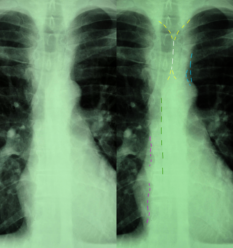
Anatomical borders that manifest themselves on chest radiographs stretch beyond readily apparent tissue interfaces (such as the heart, lungs, and aorta) to shorter, thinner and more subtle stripes and lines that may only provide partial representations of their full corresponding structure/s (Figure 2). In radiographic and radiological practices, linear opacities <5 mm in width are commonly termed “stripes” and those that are finer, only 1-2 mm in width, are often referred to as “lines.” An example is the azygoesophageal line that stretches down the mediastinum under the aortic knob (Figure 2). Adding to complexity, some lines and stripes may be present in some, but not all, radiographs (partly due to subtle differences in body position at the time of radiography or anatomical variations of internal organs between individuals). Examples of tissue borders that may or may not be visible include the anterior junctional line (meeting of the parietal and visceral pleura anteromedially), the posterior junctional line and the paraspinal lines (Figure 2).
4 PROJECTION OF A 3D SCENE TO A 2D PLANE (AND THE MORPHOLOGICAL CONSEQUENCES OF AM SUBJECT POSITION)
As radiographs represent a point projection of a 3D scene to a 2D plane, body position relative to the image receptor and X-ray point source hold important consequences for how the structure of the body is recorded on a radiograph [61]. Any structures not directly under the center X-ray beam will cast an elongated shadow as the X-rays spread from the point source, away from the center beam and toward the edges of the image receptor [61] (Figure 3). Subsequently, for 1:1 comparisons of morphology between the AM and PM films, it is necessary to replicate, as closely as possible, the body position relative to the center beam on the image receptor as per the AM reference image [1, 11, 13].
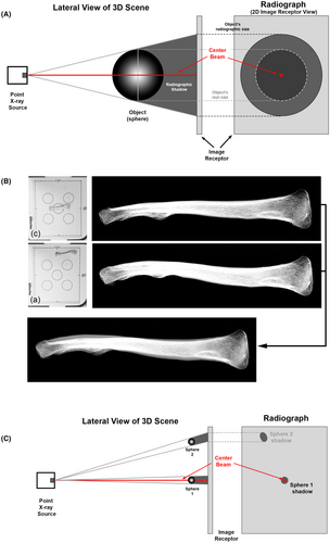
For PA chest radiographs, where standard body position has been used (see below), the cervical vertebrae in the PM image should not, for example, be imaged directly under the center beam and at the center of the image receptor—this will cast the wrong shadow. Instead, the cervical vertebrae are placed at the top center of the image receptor and in an extended position to replicate the subject's chin resting on top of the image receptor per the AM radiograph and the bones should be elevated off the receptor to provide similar arrangement and enlargement as to that embedded in the AM image. These principles apply no matter if soft tissue encased body parts, skeletons, or fragments of body parts, are used for radiographic comparison [1, 10, 11, 13]. The key is to ensure the skeletal elements replicate, as much as possible, the AM position relative to the X-ray source, center beam, and image receptor. When the remains are fully skeletonized and disarticulated, the ability of the analyst to correctly read AM body positions from the AM radiograph is vital, as the bones are no longer held together by the soft tissues in positions representative of the living state.
5 THE STANDARD POSTEROANTERIOR (PA) POSITION FOR CHEST RADIOGRAPHY
In a subject who can stand, the standard position for a diagnostic clinical AM chest radiograph is the posteroanterior view—so a clear view of the lung fields can be obtained with the scapula at the sides and without impingement on the lungs (Figure 4). This view requires the subject to be positioned such that: (1) they are facing the image receptor with the X-ray source behind them; (2) their chest is touching the image receptor; (3) their shoulders are rotated forwards and touching the image receptor; (4) their chin is resting on the top of the image receptor with the head/neck extended; (5) the backs of the hands are placed low in the lumbar region of the back; (6) the subject inhales deeply at the time of irradiation such that the lungs are fully inflated and large on the radiographic image [46, 56, 62] (Figure 4B). In most people, when a standard PA position is attained, the center beam from the X-ray source will be approximately at the T7 vertebra level [62].

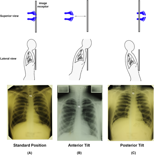
To obtain the standard PA chest radiograph position, there are a number of considerations: (1) the subject's feet must be sufficiently under the image receptor to maintain erect body posture with full chest contact on the image receptor (Figure 5); (2) the image receptor must be at the correct height, so that the subject's chin can be placed on top of the image receptor with their neck in extension (Figure 4); (3) the subject should be centered in front of the image receptor without left or right rotation or offset (Figure 6); (4) the subject's shoulder position should be symmetric, so that the chest is central in the X-ray field. If the radiographic anatomy of the AM image indicates that a non-standard position has been used for the AM radiograph (even just a slight deviation), then this same non-standard AM position must be replicated for the PM X-ray. This applies, for example, if the individual is placed high on the image receptor such that C3 and C4 are not recorded in the AM field of view. In these cases, the PM radiograph should also record the skeletal remains high on the image receptor such that the C3 and C4 are above the field of view and that the first shadow cast at the top of the image/receptor is C5.
6 COMMONLY ENCOUNTERED DIVERGENCES FROM THE STANDARD PA POSITION AS RELEVANT TO CHEST RADIOGRAPH COMPARISON
For radiographic comparison, standard positions cannot be assumed, rather exact body positions used for AM radiography must be read from the AM radiograph. The analyst must be alert to and able to read deviations from the standard position since it impacts on PM radiography for comparative purposes. Gross mispositions of the body at AM radiography are easy to recognize from the AM image. However, more subtle deviations where the lung fields are still visible, but the body position is still not standard, must not pass unnoticed and should be factored into the PM analysis. These subtle deviations often occur because the subject self-orientates in front of the image receptor following verbal instructions of the radiographer at AM radiography, or the subject inadvertently moves after the imaging position has been set by the radiographer. Common deviations are:
6.1 Subject failed to inhale (and breath hold) just prior to X-ray exposure
A “good” clinical chest radiograph is typically one that displays inflated lungs, such that ribs 1–10 are visible on each side [62] (Figure 4). The ribs can be easily counted down, by their posterior segments that form an impression of “ladder rungs” with the vertebral column [62]. When the lungs are not inflated, the (dark) lung fields will be small and the ribs close together (Figure 4C). This is not ideal for clinical examination of the lungs, and it is also not ideal for radiographic comparisons because it produces increased soft and hard tissue shielding. When the lungs are well-inflated, the lung fields are large, the ribs are well separated and superimposition of structures with the clavicles decreases [62], providing improved circumstances for comparison (Figure 4).
6.2 Subject possesses anterior or posterior tilt
If the subject's feet are not under the image receptor, their anterior chest wall will not hold full contact with the receptor, and it will not be vertically aligned, despite shoulder contact [56]. In these contexts, the subject often leans toward the receptor, so that their upper chest makes contact, but their lower chest does not, adding anterior or forward tilt [56]. This drops the medial ends of the clavicles from the typical T3 level to lower levels [56] (Figure 5) and adds forward clavicle roll that often produces: a more sigmoid-shaped clavicle shaft; the impression of broader than normal lateral ends of the clavicle; and the impression of more curved ribs since the view is down and through, rather than across, the thorax (Figure 5). It is not unusual in radiographs displaying forward tilt, for the medial clavicle ends to be positioned as low as T5 or T6 [56].
If the subject's feet are too far under the image receptor, their thorax will be in posterior tilt (away from the image receptor). In this condition, the clavicles tend to be very high in the lung fields and near the lung apexes, a straighter impression of the shafts of the clavicles will exist, conoid tubercle visibility will be enhanced, and the medial clavicles ends will be higher than T3 neural arch [56] (Figure 5). Additionally, the posterior ribs take on a more horizontal form as the thorax is irradiated from a lower angle, rather than a higher one (Figure 5).
6.3 Subject possesses left/right rotation
Left/right rotation can be recognized from multiple features. For example, offset of the trachea from the midplane of the vertebral column (discussed above), such that the spinous processes do not fall in the midplane of the trachea [62]. A small degree of asymmetry in this feature (which is often subtle) represents substantial rotation since the trachea falls close to the rotational axis at the midline. Other features that indicate rotation include: offset of the manubrium from the mediastinum into one of the lung fields; overlay of one clavicle on the mediastinum/vertebral column; asymmetry of the shoulders [62]; arching of the vertebral column, rather than vertical orientation down the center of the radiograph [56] (Figure 6). Note here that left/right rotation should not be confused with scoliosis. Scoliosis manifests with a non-straight vertebral column that arches to one side (or to both sides) with otherwise good subject positioning on the image receptor [56].
6.4 The subject is not centered on the image receptor
In poorly acquired AM chest radiographs, the subject may not be centrally orientated with respect to the X-ray center beam (or the image receptor) [62]. For example, one shoulder may be entirely outside the image receptor's field of view. This may or may not be associated with other deviations from the standard position described above.
7 IMAGE SUPERIMPOSITION PROCEDURES
Image superimposition—the procedure of overlaying two radiographs at partial transparency to compare the form of the same bone between radiographs—is distinct from and should not be confused for the superimposition of two or more structures on the same radiograph due to soft- or hard-tissue shielding (discussed above). Postmortem radiographs are ideal for image superimpositions because they provide the analyst with the capability to precisely match the orientation of structures in the AM image of interest through an iterative process. With each new PM radiograph, the AM position is increasingly triangulated upon in systematic fashion, until the skeletal position is precisely fine-tuned to the AM radiograph position. A random approach to the PM orientation of the skeletal remains should not be used.
Image superimposition provides the capacity to cross-check the subjective concordances established during side-by-side comparisons with a physical image-based procedure using known AM radiographic settings (receptor size and source-to-receptor distance). These settings are often available because source-to-image receptor distances and films sizes are standardized [46, 62]. Furthermore, they may be embedded in the metadata of electronic radiographs or detailed by standard operating procedures [46]. Due to its time intensive nature, image superimpositions are typically only conducted for those radiographic pairs thought to provide a match based on a side-by-side examination [13, 32]. The method is especially well-suited for comparisons involving skeletonized remains that can be freely orientated without obstruction [13, 32].
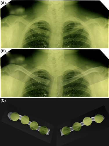
In image superimposition, the PM radiograph is overlaid on the AM radiograph at partial transparency to determine if the bony margins of the elements align in 1:1 fashion [13, 32]. Alignment indicates a match, while misalignment indicates a no-match [13, 32]. If observations made at image superimposition contradict findings of a side-by-side comparison, the superimposition always wins, as this analysis represents a physical overlay of the images, unlike the purely subjective assessment of the side-by-side comparison [13] (Figure 7). This makes it critical that the correct PM orientations of the skeletal remains, to match the AM radiograph, are used. On the superimposed images, the seamless alignment of the cortical margins should be checked along the full length of the clavicle to ensure concordance throughout [13]. The superimposition procedure is a technical one, requiring the PM position of the skeleton to be exactly replicated relative to the AM radiograph. This adds time (hours) to the analytical process, but gains in terms of analytical surety are a small price to pay when complicating case factors are present (such image quality, bone preservation state, or body position; see e.g., Figure 7).
8 EXPLAINABLE DIFFERENCES
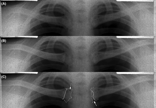
Explainable differences constitute localized discordance that is evident between AM and PM imaging sessions of the same person (ground truth true-positive match) caused by trauma or specific disease insults, which occur within the time window between AM and PM radiography. Examples include AM fracture of a bone following the AM imaging session and/or localized osteoarthritic changes, such as osteophytic lipping observed with degenerative joint changes or pseudo-arthrosis formation (see e.g., Figure 8) [12, 17, 35]. In the context of radiographic comparison, these types of discordances represent nuisance factors that are ideally avoided in the first instance by seeking AM radiographs with shorter time intervals to the individual's time of death (see above or [12, 17]). However, additional AM radiographs may not always be obtainable or may not exist, forcing the analyst to assess if local discordance(s) can be reasonably explained by an insult (including disease) event when all other skeletal morphology strongly points to a match result. Unfused medial epiphyseal flakes of the clavicle on an AM radiograph, combined with partial or full closure on the recovered clavicle represent another example of a valid explainable difference, when age (of the skeleton) at death corresponds to a plausible fusion window.
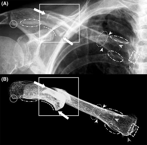
In the context of skeletonized remains, explainable differences include skeletal change arising from taphonomic processes (such as PM erosion/damage/fracture) or additional analyses (such as cuts for DNA sampling) that occur after death and prior to PM radiography. These two items often present as voids in the skeletal morphology, which of course are manifested on the PM image, but not the AM radiograph (see e.g. [32]). In many cases PM damage to the skeleton cannot be controlled-for or avoided, and so it is an item that the radiograph comparison analyst must contend. If radiographic comparisons are desired, and it is possible to delay other identification methods that require invasive and/or destructive tissue sampling, then it is preferable for the radiographic comparison to be conducted in advance of these other methods. The absence of unfused medial clavicular epiphyses at PM radiography is one more additional example of a valid explainable difference, since these epiphyseal flakes are small, delicate and are often absent from archeological recoveries of the skeleton.
Skeletal growth is not generally regarded to qualify as an explainable difference. When diffuse growth changes are suspected to apply, the analyst has three options: (1) abandon radiographic comparisons in favor of alternative identification methods; (2) locate more recent AM radiographs that eliminate the growth factor as a variable; (3) if applicable, use only the skeletally mature part of the skeleton visible on the radiograph for the comparison. Relevant to the context of cervicothoracic comparisons, it should be noted that the union of the medial clavicular flake marks the terminal end of the growth period after the bone has reached its full length, it is localized, and it does not impact the shaft or lateral-end shape that are formed from other ossification processes earlier on [48]. Subsequently, terminal union of the medial epiphysis flake can be a valid explainable difference (unlike bone growth), but only when physical evidence of union exists on the skeleton, age is already advanced, and time frames for union relative to the AM radiograph are plausible.
As explainable differences concern the criteria upon which exclusions in radiographic comparisons are based—discordances—it is critical that discordances between different individuals are not confused for explainable differences. Equally, discordances arising from mismatched body position should not be allocated to the explainable difference class, but instead these should be resolved by correcting the PM body position to match the AM radiograph (see above and [1, 10, 11, 13]). In general, explainable differences are rather infrequently encountered for soft tissue encased remains [12, 17, 35]. They are, however, relatively more common for radiographic comparisons involving skeletal remains, since field-disposed remains are often subject to weathering [32].
9 AN ADVANCED CHEST RADIOGRAPH COMPARISON EXAMPLE
9.1 Case background
The radiographic comparison conducted below highlights multiple complicating factors that mark it as an advanced comparison (regional image degradation, non-standard body position, relatively young age of decedent, and timespan between AM imaging and death). It is one, nevertheless, that still allows correct analytical findings to be reached, as confirmed by mtDNA analysis of the same skeleton compared to family reference samples as undertaken subsequent to the radiographic comparison result. The case demonstrates image superimposition alignment of the clavicles after matching the non-standard AM body position and what can be done with the chest radiograph comparisons under extreme test conditions. The case highlights the importance of paying special attention to the body position, even when it is close to, but not, standard. The case comes from the Korean War context of US military repatriation.
This case concerned an initial comparison to four potential candidates and skeletal elements comprising C5-T2 vertebrae, left clavicle and right clavicle. Three of these candidates were excluded due to salient discordances at juxta-comparison (side-by-side comparison), leaving one candidate as an ongoing possibility for a match by further, more detailed, examination.
9.2 AM radiograph
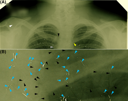
The potentially matching individual was represented by a single differentially deteriorated 14 × 17-inch double-emulsion film (Figure 9). This radiograph was in well-advanced vinegar syndrome, where the acetate backing had shrunk causing crazing (network of elongated bubbles) across the radiographic picture (Figure 9). In the center of the film, physical splitting of the radiograph was evident, presenting clear-space cracks and representing further significant deterioration (Figure 9).
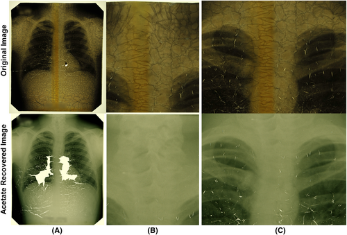
The film was rejuvenated by acetate recovery, whereby both image pellicles from the one film (double-emulsion film) were stripped from their middle acetate backing layer and the better-preserved pellicle reconstructed from its fragments, on glass, in a thin film of fluid prior to imaging [13, 63]. At acetate recovery, some of the center parts of the X-ray image were too deteriorated to be reconstructed (Figure 9). In regions of heavy channeling, residual silhouettes of the channels were left on the radiograph's pellicle after the acetate backing was removed (Figure 10). In the mediastinum region, the pellicle displays some hairline cracks that could not be rectified by piece movement at reconstruction, however, the integrity of the image film is not compromised in other more peripheral regions, such as in the region of the cervical vertebrae (Figure 10). The cervical and shoulder regions were less affected by channel silhouettes and resolution in these outer regions is generally good, unlike the more central region including the medial ends of the clavicles that are obscured by: (1) multiple silhouettes of acetate shrinkage/channels remaining on the recovered film; (2) poor image resolution in this area (Figures 9 and 10).
9.3 Skeleton
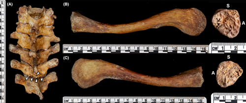
The skeletal elements are well-preserved, with T2 exhibiting the only substantial damage—T2 mid-spinous process fracture and inferior lamina with missing segments (Figure 11). The medial epiphyses of the clavicles are entirely open and billowy without sign of epiphyseal flake union (Figure 11). The time between AM radiography and suspected time of death is around 2.6 years (very short); however, the age of the individual at AM radiography is suspected to be young—possibly as low as 15–16 years.
9.4 AM body position
The acetate recovered AM radiograph demonstrates that the subject's lungs were close to, but not fully inflated at the time of radiography—the 10th rib is not clearly visible in lung fields on either side of the body (Figure 9). There is also a substantial forward tilt of the subject indicated by: (1) the low position of the medial clavicle ends at the T5 level; (2) the left clavicle overlapping with the aortic knob on the left side; (3) the tall lateral clavicle ends indicating near inferior surfaces facing the X-ray source—especially pronounced on the right side (Figure 10). There is moderate right-side rotation of the thorax indicated by: (1) greater view of the right than left shoulder; (2) right-side visibility of the manubrium well-beyond the right side of the mediastinum; (3) clear view of the right clavicle's sternal end without any overlap on the mediastinum; (4) increased manubriosternal joint visibility and gap to the mediastinum/T4 on the right side (Figure 10). In the mid-thoracic vertebral region (T5–T9), there are indicators also of scoliosis, however, the radiographic film becomes substantially fractured and fragmented in the mid-low right thoracic region making conclusive determinations below the T6/7 level difficult (Figure 9).
The classically displayed right-side rotation (compare Figures 6 and 10), indicates that the sternal end of the left clavicle falls on the mediastinum (see e.g., Figure 7 for other examples of higher clarity radiographs from other individuals in similar body position), and not at the pseudo-margin indicated by the dark radiolucent line adjacent to the vertebral column (Figure 10A yellow arrow). This is a critical observation for both side-by-side analysis and image superimposition—failure to recognize this feature gives rise to anatomical discordances at the medial end and across the full-length of the clavicles (including lateral ends) that works against the drawing of correct conclusions (see e.g., Figure 12). The pseudo-medial end of the left clavicle in this case makes the right-side rotation easily missed without careful analysis and alert attention to the co-contributing image degradation factors (Figure 12).

9.5 PM radiography
PM radiographs of the C5-T2 vertebrae, left clavicle and right clavicle at positions on the image receptor representative of that used at AM radiography, demonstrate near-exact concordance supporting a match result (Figure 13) and enables precise PM/AM superimposition of the clavicles (Figure 14). Table 1 documents 19 items of concordance in the side-by-side comparison—but many more concordances are additionally evident on the AM and PM images. The 19 concordances exceed the recently proposed criteria by other authors for only one or two concordances for a match result using thoracic vertebrae (see [5]). Image superimposition of the clavicles shows near-perfect alignment of the PM radiographs with the AM images, cross-validating the side-by-side comparison results on image-only criteria (Figure 14). Per the right-side rotation evident on the left side of the AM radiograph, the left clavicle's medial end falls over the mediastinum and the paratracheal lines. This, in part and together with image degradation factors, obscures view of the clavicle on the AM radiograph in this region. Consistency in the density of the right clavicle's medial margin between the AM and PM images and the height of the lateral clavicle ends (inferior orientation in both images) is consistent with the anterior tilt and T4/5 position of the medial clavicle ends. The forward roll on the clavicles at PM radiography to obtain the AM anterior tilt position in its fullness is substantial—c. 70° to 80°. Note here that the medial ends of the clavicles are also placed low on the image receptor and near the center beam to replicate the AM position and corresponding radiographic bone morphology.
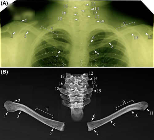
| Arrow | Element(s) | Concordance |
|---|---|---|
| 1 | R Clavicle | Large paddle-shaped acromial end |
| 2 | R Clavicle | Superior cortical margin thickness tapers toward the acromial end |
| 3 | R Clavicle | Thickened inferior cortical margin relative to the superior cortical margin at the site of lateral flexion |
| 4 | R Clavicle | Superior cortical margin thickness gradually tapers toward the sternal end |
| 5 | R Clavicle | Rounded cluster of radiolucencies consistent with a rhomboid fossa |
| 6 | L Clavicle | Slight flaring of the superior margin at the sternal end |
| 7 | L Clavicle | Multiple small radiolucencies along the inferior margin in the region of the rhomboid fossa |
| 8 | L Clavicle | Undulating inferior endocortical margin just medial to the mid-shaft region |
| 9 | L Clavicle | Less pronounced curvature of the left superior clavicular margin relative to the right clavicle in the region of the lateral point of flexure |
| 10 | L Clavicle | Thickened inferior cortical margin relative to the superior cortical margin at the site of lateral flexion |
| 11 | L Clavicle | Large paddle-shaped acromial end |
| 12 | C5 | Clear and marked superior projection of the left uncinate process in an inverted V-shape |
| 13 | C5 | Distinct projections of the bifid spinous process, with the left portion angled more vertically than the right portion |
| 14 | C5 | The lateral aspect of the left inferior articular process extends inferiorly and comes to a point |
| 15 | C6–C7 | Margins of the bifid spinous process projections of C6 are superimposed with the tip of the spinous process of C7 |
| 16 | C7 | Large, inverted-U-shaped margin of the root of the spinous process, due to marked superior orientation |
| 17 | C7 | Left superior margin of the neural arch sits more inferiorly relative to the right margin |
| 18 | T1 | Margins of the root of the spinous process are radiodense, narrow, and incline slightly to the right |
| 19 | T1 | Radiodense inferolateral margin of the left transverse process is obliquely angled relative to the right transverse process |
In the above-presented case, if the left clavicle's medial end is not correctly identified and/or right-side rotation of the body or anterior tilt at AM radiography is missed, the concordance in vertebrae anatomy will present the analyst with a difficult conundrum—the vertebrae hold salient concordances, but the clavicles hold salient differences. Failure to pay careful attention to the body position at AM radiography, therefore, holds the capacity to predispose one of three major errors: (1) wrongful identification of commingling; (2) wrongful exclusion or inconclusive determination; (3) wrongful invoking of “explainable differences” to obtain a match result. As demonstrated in this case, the AM radiograph must drive what body position is used at PM radiography, to enable trustworthy and reliable chest radiograph comparison results.
10 CONCLUSIONS
Forensic anthropologists are increasingly being called upon to conduct radiographic comparisons in the forensic DVI context. The seemingly common perception that radiographic comparison methods, including chest radiograph comparison methods, are straight forward and easy to conduct is an over-simplification that risks/invites error. In both civilian and military repatriation contexts, cases can be (and often are) complex. Radiographic comparison analysts must be proficient in: (1) reading all details of AM body position including almost, but not quite, standard body positions; (2) reading hard and soft tissue radiographic anatomy alike; (3) differentiating image artifact from anatomical signal. A case highlighting the importance of all three factors acting concurrently emphasizes this relevance.
ACKNOWLEDGMENTS
Acetate recoveries for AM radiographic films presented in this paper were undertaken by Chicago Albumen Works. We acknowledge the DPAA analysts whose case report images form components of the information presented herein. Open access publishing facilitated by The University of Queensland, as part of the Wiley - The University of Queensland agreement via the Council of Australian University Librarians.
CONFLICT OF INTEREST STATEMENT
The authors have no conflicts of interest to declare.
DISCLAIMER
The views and opinions expressed herein are entirely those of the authors. They are not to be construed as official views of any institutions, editorial boards, or governing boards to which the authors may be affiliated.


