Modified image algorithm to simulate seismic channel waves in 3D tunnel model with rugged free surfaces
Paper presented at the 82d SEG Meeting, Las Vegas, NV, USA, November 2012, and at the 83rd SEG Meeting, Houston, TX, USA, September 2013
ABSTRACT
The existence of rugged free-surface three-dimensional tunnel conditions in the coal seams, caused either by geological or mining processes, will inevitably influence wave propagation characteristics when the seismic waves go through the coal mines. Thus, a modified image algorithm has been developed to account for seismic channel waves propagating through this complicated topography with irregular free surfaces. Moreover, the seismic channel waves commonly exhibit damped and dispersive signatures, which is not only because of their own unique sandwich geometry of rock–coal–rock but also because of the viscoelastic behavior of coal. Considering the complexity of programming in three-dimensional tunnel models with rugged free surfaces, an optimized vacuum grid search algorithm, enabling to model highly irregular topography and to compute efficiently, is also proposed when using high-order staggered finite-difference scheme to simulate seismic channel wave propagations in viscoelastic media. The numerical simulations are implemented to investigate the accuracy and stability of the method and the impact of coal's viscoelastic behavior on seismic channel wave propagation characteristics. The results indicate that the automatic vacuum grid search algorithm can be easily merged into high-order staggered finite-difference scheme, which can efficiently be applied to calculate three-dimensional tunnel models with rugged free surfaces in the viscoelastic media. The simulation also suggests that the occurrence of a three-dimensional tunnel with free surfaces has a remarkable influence on the seismic channel wave propagation characteristics and elastic energy distribution.
INTRODUCTION
Compared with surrounding rocks, coal seam commonly presents significantly low-velocity and low-density characteristics, and it is generally more viscous. Moreover, it is well known that this special sandwich geometry of rock–coal–rock will generate guided waves, which are typically damped and dispersive. This unique geometry causes energy of seismic channel wave trapped inside the coal seam, which may be useful in the mining applications (Evison 1955). Krey (1963) theoretically proved the existence of seismic channel waves in the coal seam. He argued that the sandwich geometry of rock–coal–rock would generate seismic channel waves, which would spread along the coal beds and surrounding rocks. Lagasse and Mason (1975) applied the numerical simulations to estimate the particle displacement of seismic channel waves. Dresen and Freysatter (1976) studied the elastic properties of seismic channel waves when minor faults occur in the coal mining. Meanwhile, they also implement physical modelling experiments to specifically study propagation properties of Rayleigh surface wave. Then, they focused on a leaky model, one of the seismic channel wave models, and generalized seismic channel wave theory (Franssens, Lagasse, and Mason 1985). The propagation properties of the Love channel wave was studied when cracks occurred in the coal seams, and they found that the Love channel wave is more sensitive to anisotropy than coal beds in regards to cracks (Liu, Crampin, and Roth 1992).
Currently, the 3D void tunnel with rugged free surface existing in the coal seam, which is generally caused either by geological or mining processes, has been becoming especially destructive since modern mining equipment is been used to produce the fossil fuel (Dresen and Ruter 1994; Brady 2003; Wang et al. 2008). Because such unexpected void tunnel could accumulate massive underground water, the serious mining accident may occur due to water inundation, which can generally not be seen by conventional geophysical surveys. Therefore, the mining work would be efficiently improved if such void tunnels were known in advance. Although we have been applying the seismic channel wave exploration method in mining, characterizing the wave propagation features of seismic channel waves are still challenging, especially if such abnormal geometry exists in coal seam. Additionally, the irregular free-surface 3D tunnels located in the coal seams, forming a physical boundary, will inevitably influence the characteristics of seismic channel waves. The ability to model such complicated and irregular boundary conditions is an alternative way to predict these unexpected abnormal structures, which would dramatically decrease the mining risk. However, this situation has not been thoroughly considered yet when studying the seismic channel waves in the coal seams. Hence, the numerical studies of seismic channel waves are essentially necessary when a 3D void tunnel in the coal seam is involved. Here, we propose to use numerical simulations to investigate the propagation properties of seismic channel waves in 3D tunnels with rugged free surfaces.
More importantly, the viscosity of both the surrounding rocks and the coal seams cannot be ignored due to the sedimentary rock properties. Theoretical, numerical, laboratory, and field data indicate that seismic waves travelling through a coal seam is significantly damped in viscoelastic media (Buchanan 1978, 1987; Krey, Arnetzl, and Knecht 1982). In particular, the complicated coupling mechanisms of seismic waves between the surrounding rocks and coal seams vary with the changes in the quality factors as well, which is an indispensable parameter to characterize the attenuation and dispersion of viscoelastic media. Hence, from the point of view of a real case, it is an essential parameter for studying the seismic channel waves propagating in 3D viscoelastic media.
Considering the complex features of actual media, modelling the wave propagation along a free-surface model is becoming an important issue (Bouchon, Campillo, and Gaffet 1989; Tessmer, Kosloff, and Behle 1992; Robertsson 1996; Hestholm and Ruud 2001). The finite-element method (FEM) handles models with free-surface boundaries occurring at the air–solid boundary. FEM is suitable for complex geometries; however, it is computationally expensive (Mu 1984; Teng 1988). The pseudo-spectral method is a powerful numerical technique because of its accuracy and efficiency; unfortunately, this method cannot directly handle media with curved free surfaces (Orszag 1980; Gazdag 1981; Kosloff and Baysal 1982). Recently, boundary integral equations and boundary element methods are other alternative schemes to simulate wave propagation for a curved free-surface case (Durand, Gaffet, and Virieux 1999). Compared with the aforementioned methods, the finite-difference scheme (FDS) is simpler and flexible. Various FDSs have been proposed to simulate the free-surface topography. One of them is the image method (Robertsson 1996; Levander 1988). Then, based on existing image methods of an FDS, Wang and Zhang (2004) proposed to use an improved algorithm to implement curved free boundary conditions. The purpose of this paper is to use numerical simulations to study seismic channel wave propagation properties when the complicated topographic 3D tunnels with free-surface boundaries existing in the sandwich model of rock–coal–rock. The high-order staggered-grid FDS (O(2, 6)) and that of (O(2, 4)) is applied to the horizontal case and the rugged case in this paper, respectively.
Robertsson (1996) improved the image method using only 12 grid points per minimum wavelength to guarantee the calculation accuracy for rugged free surfaces. It drastically reduces computation time. Although increasing the grid points can improve the calculation accuracy, it is more time-consuming. When implementing numerical simulations, a good numerical algorithm should balance the calculation accuracy and computation efficiency, especially when considering the irregular free-surface topography conditions. Robertsson's image scheme is relatively expensive in terms computation time due to its classification of grid types, especially in the 3D case. By setting the normal stress components in the middle of the grid (Fig. 1a) and letting the free surface pass through the grid points at the location of the shear stress component, the Robertsson's image method is simplified. Generally, the position of vacuum grids are marked in advance in the program; however, the proposed automatic vacuum grid search algorithm is capable of searching unknown position of vacuum grid, which makes the image method more flexible and efficient in the rugged free-surface 3D tunnel case. Meanwhile, this automatic vacuum grid search algorithm does not influence the modelling accuracy. On the other hand, based on our program experience, it can be easily merged into existing FDS and into parallel computation algorithms. This automatic vacuum grid search algorithm is an adaptation of the high-order staggered-grid velocity–stress approach (Mu and Pei 2005).

In summary, firstly, the existence of irregular free-surface 3D tunnels make assignable influence on the characteristics of seismic channel wave propagation; secondly, the optimized image algorithm can perfectly simulate the 3D tunnel model with rugged free surfaces to reflect actual coal seam mining; and thirdly, the automatic vacuum grid search algorithm merged into high-order staggered FDS improves computation efficiency. This paper will be organized as follows. Firstly, there is a brief discussion on the free-surface conditions in viscoelastic media, followed by the designation of rugged free surface of 3D tunnel models; then, an automatic vacuum grid search algorithm is given to improve the computation efficiency in the 3D tunnel model. Finally, synthetic examples are given to discuss both the tunnel effect and viscosity effect on the propagation characteristics of seismic channel waves.
FORMULATIONS
Governing equations
Generally, two kinds of seismic channel waves are observed in the coal seam: one is Love channel wave, and the other one is pseudo-Rayleigh channel wave. They may be viewed as the result of constructive interface between multiple reflected SH waves (Love) or P and SV waves (pseudo-Rayleigh). The viscosity is another significant factor influencing the seismic channel wave properties. In order to investigate the seismic channel wave propagation in the viscoelastic media, the generalized standard linear solid (GSLS) model is applied in this paper (Zener 1948). The following three sets of equations are solved.
 (1)
(1) (2a)
(2a) (2b)
(2b) (3a)
(3a) (3b)
(3b) denotes the
  th component of the symmetric stress tensor;
  represents the ith component of the particle velocity;
  indicates the memory variables;
  and
and  are the viscoelastic strain relaxation times for the P- and SV-waves, respectively;
  is the viscoelastic stress relaxation time for both the P- and SV-waves; ρ denotes the bulk density of particle;
  represents the external force; μ is the relaxation modulus corresponding to SV-wave; and π is the relaxation modulus corresponding to P-waves. When
  , the above equations can be reduced into standard linear viscoelastic equations. The partial differential equations 1, 2a, 2b, and 3a, 3b are numerically solved with an explicit, time-domain high-order staggered-grid finite-difference technique. Specifically, Nth-order space accuracy and second-order time accuracy are applied, respectively.
 satisfies the following boundary conditions:
 (4)
(4)In this paper, the constitutive equations in the viscoelastic media described as the GSLS model (equations 1, (2), and (3)) should be constrained along a continuous free-surface boundary; therefore, the free-surface conditions described by equation 4 are satisfied.
IMPLEMENTATION OF STAGGERED FINITE-DIFFERENCE SCHEME
A planar free-surface case in a 3D tunnel
In order to solve the free-surface boundary conditions in the finite-difference scheme (FDS), based on an image method, an alternative horizontal free-surface implementation is proposed by Levander (1988). According to the principle of irregular free-surface discretization, a finite-difference modelling of irregular free surfaces is proposed to decompose into horizontal and vertical segments approximated by the piecewise continuous lines (Jih, McLaughlin, and Der 1988). Fornberg (1988) suggested to deform the interior of the finite-difference grid to match internal free-surface boundaries. Tessmer et al. (1992) and Carcione and Wang (1993) employed an elegant solution to isolate the finite-difference grids when free surfaces are involved.
The coal tunnel is generally 3D; therefore, it is necessary to extend the image method proposed by Robertsson (1996) and Wang and Zhang (2004) for a 3D case in a tunnel. In this discussion, the z-axis is assumed downward and positive, and the free surface is placed at  as shown in Fig. 1(b). Extending the 2D case to 3D may cause more than one free surface in each grid cell. Here, we only pick up the XOY plane of grid in the z-direction to apply the image method; the remaining five free planes can be applied by replacing its corresponding stress components and velocity components, accordingly.
We set the free surfaces pass through the grid points at the location of shear stress components  than the locations of normal stress component
  (Wang and Zhang 2004). In Fig. 1(a), the normal stress is set up in the middle of a staggered-grid cell, and shear stresses are distributed on the 12 edges of the grid cell .The physical parameters correspond with the number markers in Fig. 1(a) listing in Table 1. In Table 1, the physical indication of each parameter has been represented in equations 1, (2), and (3).
| Grid net | 1 | 2 | 3 | 4 | 5 | 6 | 7 |
|---|---|---|---|---|---|---|---|
 , ,  , ,  , , |
 , , |
 , , |
 , , |
||||
| Physical parameters |
 , ,  , ,  , , |
 , , |
 , , |
 , , |
μ, | μ, | μ, |
| π, λ, 2μ, |
 |
 |
 |
 |
 |
 |
|
 , ,  , , |


 (5a)
(5a)


 (5b)
(5b) ; then, the free surface will be at the next downward grid. The image formulation can be written as


 (6a)
(6a)

 (6b)
(6b) are integer numbers in equations 5(a), 5(b), 6(a), and 6(b), and
  is the grid length along the z-axis. The memory variables have the same formalisms for the free surface located at the bottom of a 3D tunnel and at the top of a 3D tunnel accordingly. Compared with equation 1, particle velocity (
 ) in this case is located in the free surface, which requires recalculation, but the physical parameters are zero, and as a result, the physical parameters (density) of the neighboring grid net is applied when recalculating the corresponding particle velocity. The same procedure is applied to solve the free surfaces that are perpendicular to thex-axis or y-axis.
This implementation has two advantages. Firstly, the normal stress constrain is not required since it is not located on the free surface directly. It only approaches to be zero indirectly through equations 5a and 5b. Secondly, if a corner occupied by a vacuum is encountered by the topographic free surfaces, the existing image method just forces the shear stress to be zero. This is more efficient and is physically reasonable for a free-surface corner (Wang and Zhang 2004).
A free surface extension in the presence of topography
- Case A. It is a vertical free surface. It has one neighbor itself, or one neighbor of A, C, or D. The free surface passes through
 and
and  . To perform the free boundary condition, the shear stress components of both
  and
and  are set to zero; then, the shear stresses
  and
and  and the normal stress
  are imaged with respect to the vertical free surface as follows:


 (7a)
(7a)


 (7b)
(7b)- Case B. It has one neighbor itself, or one neighbor is either case H or case E. The free surface passes through
 and
and  . Previous equations (5) are applied; we need to pay attention on the imaging direction.
 - Case C. The only point at the free-surface segment is
 . In this case, the shear stress
  is directly set to zero; therefore, no imaging is needed.
 - Case D. The free surface passes through
 , and
, and  . Since it is the case that one grid having two free surfaces, in which one is horizontal case and one is vertical case, therefore, we directly apply the corresponding image method to handle the free surface conditions.
 - Case E. It is similar to the case C, except the associated grid is nearly in solid medium. Since the only point at the free surface segment is
 , therefore, it is simple to set to zero as case C did. No imaging is required.
 - Case F. This is another vertical free surface. Compared with Case A, the vacuum area is to the left. Therefore, the imaging implementation is similar to Case A, but the imaging direction is opposite.
- Case G. This is the case that has one grid with two free surfaces, in which one is horizontal case and one is vertical case, just like Case D. However, the associated grid is nearly in the vacuum area. Therefore, we directly apply the corresponding image method to handle the free surface conditions accordingly. Here, the imaging direction is opposite compared with Case D.
- Case H. It has one neighbor itself or one neighbor of case A, C, or B. The free surface passes through
 and
and  , and the shear stress component
  is set to zero; no imaging is required for
  if the neighbor below is Case A. Otherwise, the shear and normal stress components are needed to be mirrored with equation (7).
AUTOMATIC VACCUM GRID SEARCH ALGORITHM OF A 3D TUNNEL MODEL
The image method would be applied to every free surface even if they share the same grid. It is not only because the grid types are numerous but also because the corresponding applied image method is different, which is more time-consuming and difficult to program. Therefore, we have simplified the overclassified grid-type image method (cases C and E) in the irregular free-surface 3D tunnel case.
Since the different type imaging conditions are applied in the different directions, moreover, there is more than one free surface in each single grid cell. Therefore, we propose an automatic vacuum grid search algorithm to judge the grid type in advance. Then, the corresponding image method is applied accordingly to free surface type. It is not only advantageous on the programming but also capable of calculating the unknown vacuum grid in the modeling. This section details this automatic search algorithm.
The free surfaces of light-grey vacuum grid cells at both the bottom and top are needed to apply the image method as discussed above. Here, we take the blue point C in the YOZ plane of the rugged free-surface 3D tunnel model in Fig. 1(c) as an example. Because the space order is the fourth here, physical parameters of two grid cells next to blue grid C in each direction are involved to update the particle velocity of blue grid C. We can see that one of the grid cells in both y- and z-directions is located in the vacuum; hence, the image method should be applied because, according to the material properties, the normal stress and shear stress components in the vacuum are zero.
- (a) Grid type determination: According to the difference of physical parameters, mark the grid cells located in the channel and distinguish them with the grid cells with free surfaces.
- (b) Image method application: According to the distance between the calculating grid net and free surface of the tunnel, apply the image method accordingly. Here, if the space order is fourth, then the image method should be applied within two grids next to the free surface. Taking the grid point A as an example, if the physical parameters at point A is zero, whereas that is not zero at the next two grids in the x, y, and z forward and backward directions, then it means Point A satisfies the free-surface condition, and the program will automatically apply the corresponding image method.
- (c) Regular grid particle velocity updating calculation: Apply the conventional staggered FDS to the regular grid square in the particle velocity updating loop. Moreover, for the particle velocity updating of grid points using the image method, the sub-program for setting up the stress component before calculating particle velocity is as follows.
- (1) Based on the calculating grid points as the relative origin of the coordinate space, the free surface of the tunnel grid using the image method is oriented. There are six kinds of image algorithms in the 3D tunnel model (positive and negative in the x, y, and z directions, respectively). If free surfaces show up in more than one orientation of the tunnel grid, we apply the image method to each accordingly until all free surfaces of the tunnel grid points are calculated.
- (2) Specific particle velocity updating of free surface in each direction. First, search for locations of free interface because the tunnel surface was marked in step 1. Second, set up a stress value in the vacuum grid point. Moreover, pay close attention to the orientation of the free surface because its corresponding image method will be different.
- (3) Repeat step 1 if the grid type satisfies the image method.
This automatic vacuum grid search algorithm only slightly increases computer memory and computation time. Hence, it is very portable and efficient even in the 3D case. It is crucial that the tunnel cells will be in even order (2L) in front of the free interface to guarantee the successful implementation of the image method.
In summary, when considering the actual case of a 3D tunnel with two free-surface boundary conditions, first, we establish the corresponding free-surface boundary condition equations. Then, based on Wang's classification of a staggered-grid type in the finite difference, we use the above-described automatic vacuum grid search algorithm to simulate the seismic channel wave propagation in the viscoelastic coal seam media with a 3D tunnel model.
SYNTHETIC EXAMPLES
1 Irregular free-surface 3D tunnel model algorithm test
In order to test the adaptation of irregular free-surface 3D tunnel model implementation in the high-order staggered finite-difference scheme, a horizontal model and a rugged 3D tunnel homogenous model are simulated in the elastic media. For the horizontal free-surface 3D tunnel model, the model size is  , and the grid net is
  . For the rugged free-surface 3D tunnel model, its slope angle is 18.5°, the model size is
  , and the grid net is
  . An explosive source is located in the middle of the free surface at 2 m away from the tunnel. The Ricker wavelet is applied, and its dominant frequency is 150 Hz. According to the stabilization criteria, the time interval is set as 0.1 ms with an O(2, 6) accuracy and O(2, 2) accuracy on the horizontal free-surface and the rugged free-surface 3D tunnel models, respectively. The physical parameters of vacuum grids are zero, whereas for the regular grids, the P-wave and S-wave velocities are 1,700 m/s and 1,000 m/s, respectively. The density is 1,300 kg/m3.
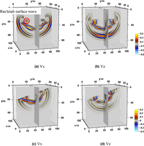
The x component of particle velocity in Fig. 2(a) shows that a Rayleigh surface wave is generated around the tunnel free boundary. The wavefield of a 3D tunnel model with a free-surface model indicates that the automatic vacuum grid search algorithm application is correct. Namely, based on the corresponding types of free surfaces, the proposed vacuum search algorithm can perform free-surface conditions accordingly. Compared with the horizontal 3D tunnel case, the rugged free-surface 3D tunnel model requires more grids per each minimal wavelength. The result is analogous to the horizontal tunnel model, which indicates that the image method works well in rugged free-surface 3D tunnel models as well.
2 3D tunnel effect on seismic channel wave
We have verified that the automatic vacuum grid search algorithm of irregular free-surface 3D tunnel models is effective and portable. For the actual case of coal mining, the mining tunnel is usually 3D with almost horizontal free surface. It looks like a cuboid, and each surface could be free surface to which should be applied the corresponding image algorithm according to their specific coordination. Hence, in order to approach to the field case, the focus here will be on the horizontal-free-surface 3D tunnel model to study the channel effect on properties of seismic channel waves. A sandwich geometry of the rock–coal–rock physical model is built to investigate the wavefield properties when a 3D channel exists in the viscoelastic coal layers (Fig. 3). Physical parameter and quality factor distribution are listed in Tables 2 and 3, respectively.
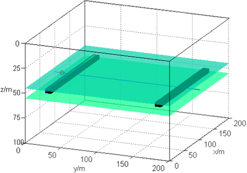
 , the thickness of coal bed is 10 m, which is located in the middle coal bed of the z direction. The size of the two 3D tunnels is 160 m by 4 m by 4 m, which is away the model boundary 20 m in the y direction, and the length is 160 m in the x-direction. The red circle is explosive source located in (100 m, 10 m, 50 m). The green planes indicate the boundary of coal seam. The black cuboid is the channel position in the 3D rock–coal–rock model.
| P-velocity m/s | S-velocity m/s | Density g/cm3 | Thick m | Lithology |
|---|---|---|---|---|
| 2800 | 1618 | 2.2 | 45 | Sandstone |
| 2200 | 1270 | 1.4 | 10 | Coal seam |
| 2800 | 1618 | 2.2 | 45 | Sandstone |
| Model |
 |
 |
 |
 |
|---|---|---|---|---|
| 1 | 80 | 40 | 50 | 22 |
| 2 | 25 | 15 | 10 | 5 |
Figure 3 displays the 3D schematic of a systematic rock–coal–rock geological model. The model size is  , and the grid net is
  in the x, y, and z directions, respectively. An explosive source is located in the red circle (100 m, 10 m, 50 m) at the coal seam in Fig. 3. The Ricker wavelet is applied, and its dominant frequency is 150 Hz. According to the stabilization criteria, the time interval is 0.1 ms with O(2, 6) and O(2, 6) accuracy on the regular grid and the vacuum grid in the high-order staggered finite-difference scheme, respectively. In Table 3,
  and
and  denote the P-wave quality factor of the surrounding rocks and the S-wave quality factor of surrounding rocks, respectively.
  and
and  represent the P-wave quality factor of coal seams and S-wave quality factor of coal seams, respectively. The model 1 parameters of Table 3 are applied in the following modelling.
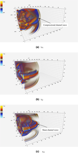
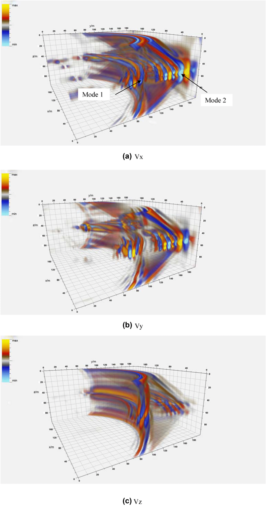
Compared with non-tunnel models (Li, Zhu, and Ji 2013), the existence of 3D tunnels in the coal seam has a remarkable influence on seismic channel wave propagation and wave energy distribution of all particle-velocity components. Due to the free surfaces of 3D tunnels, the more intensive surface waves are generated (Fig. 5a–c); meanwhile, these surface waves are multiple reflected within the coal seam to develop more complicated seismic channel waves. The wavefield energy is mainly trapped in the coal seams. The front part of the seismic channel waves is a pseudo-Rayleigh channel wave intervened by P-wave and SV-wave, and its velocity is about 2,300 m/s (Fig. 4a), which is between the P-wave velocity of the coal seam and that of the surrounding rock; the back part of it is a Love channel wave intervened by the converted SH-wave of surrounding rocks and the SH-wave of coal seams, and the velocity is about 1,550 m/s (Fig. 4c), which is between the S-wave velocity of coal seam and that of surrounding rock; and more importantly, the special seismic channel wave has been generated due to the Rayleigh surface wave excited by the existence of 3D tunnel, which cannot be observed in the rock–coal–rock model without a 3D tunnel. According to the induced seismic wave interference model, the aforementioned seismic channel waves are named as a compressional seismic channel wave, shear seismic channel wave, and a surface seismic channel wave accordingly. Here, the occurrence of the surface waves is caused by the conversions of P-wave and converted SV-wave. Figure 6 shows a series energy of seismic channel waves trapped in the coal seam, which is because, as the seismic channel wave propagates, the different modes of the seismic channel waves will spread out. The first mode and the second mode of the seismic channel wave can be distinguished. Speaking of wave energy distribution of all particle velocity components, although seismic channel wave concentrates most wave energy within the coal seam, part of the seismic energy transmits into the wall rock, propagating as shear wave velocity of the surrounding rock.
3 Quality factor variations effect on seismic channel waves
This section will continuously focus on horizontal-free-surface 3D tunnel models to study the effect of quality factor on the properties of seismic channel waves. Another set of rock–coal–rock physical models are built with the quality factor variation as shown in model 2 of Table 3, whereas other parameters are the same as model 1.
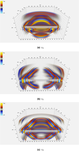
According to Figs. 7 and 4, we can observe that the energy of seismic channel waves is more concentrated within the coal seam as the quality factor increases; additionally, the shear seismic wave is more intensive (Figs. 7c and 4c). For the surrounding rocks, as quality factors increase, the intensity of the compressional wave in the wall rock decreases dramatically, but the intensity of the shear wave in the wall rock remains almost constant.
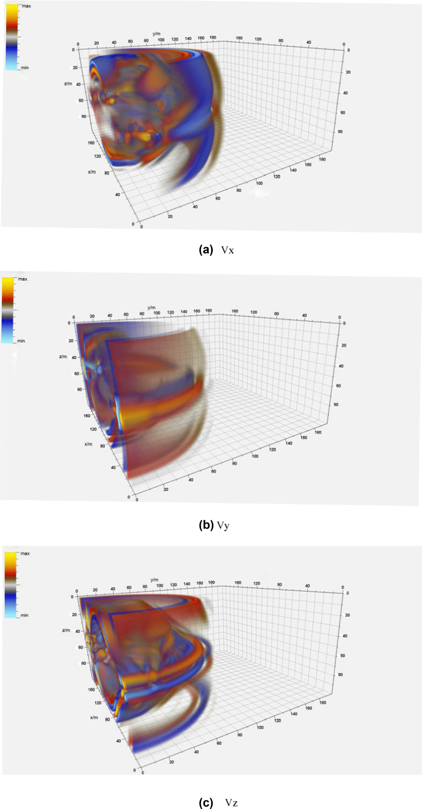
Because the z component of particle velocity tends to intervene, the modes of shear seismic channel wave are easier to distinguish (Figs. 7c and 4c). Although shear seismic channel waves concentrate mostly seismic wave energy, partial energy transmitting into wall rock propagates as shear wave velocity of the wall rock.
In considering the contrast of intensity between the wall rock and coal beds, the x component of particle velocity has a higher seismic channel wave transmission wave ratio, which remains relatively stable while quality factors increase/decrease. Thus, thex component may be more advantageous for seismic channel wave exploration.
DISCUSSIONS
This research has numerically simulated the seismic wave propagation in the sandwich geometry of rock–coal–rock with rugged free-surface 3D tunnels in the viscoelastic media. It is no doubt that the complexity of seismic channel wave could be affected not only by the aforementioned factors but also by other related physical parameters. Thus, it is also profitable to discuss other possible factors that influence the seismic channel wave properties. This discussion should contribute to a deeper understanding of seismic channel wave in the future.
Effect of coal seam thickness
The thickness of coal seams varies according to the specific mining processes. Because the seismic channel waves are primarily interfered with by the P-wave and S-wave within the sandwich geometry of rock–coal–rock, the thickness of coal seams is a key physical parameter to significantly influence the seismic channel wave propagation and its corresponding elastic properties. Of course, the thinner the layer of coal seam, the more chance of interference by P-wave and S-wave; this will cause more intensive seismic channel waves. Consequently, using the seismic channel wave is a good technique in coal mining, especially in certain thickness of coal layers.
Effect of quality factor ratio
The viscosity of sedimentary rock is an indispensable factor to characterize the elastic properties of seismic channel wave. As mentioned above, the viscosity not only influences the modes distribution of seismic channel wave but also has an impact on the wave energy distribution of coal seams and the surrounding rocks. However, the quality factor ratio of coal seams to surrounding rocks should be considered in further study, especially when considering the wave energy distribution.
In addition to the impact of coal seam thickness and viscosity, there are other significant factors that impact seismic channel waves. These include the other elastic parameters and rock physics parameters, such as the distance of seismic channel wave propagation, the porosity, fluids saturation, and anisotropy of the coal seams and surrounding rocks. As a result, this research of seismic channel waves only initiates; subsequently, more systematic investigations should be carried out on this topic.
CONCLUSIONS
Three-dimensional tunnels with rugged free surfaces in coal mines will cause serious damage if they cannot be predicted in advance. In accordance with what is known of sandwich geometry of rock–coal–rock influencing the seismic channel propagation, a numerical simulation method should be used to study the propagation properties of such seismic channel waves, which have normal amplitude within the coal seam, whereas the amplitude in the surrounding rocks rapidly approaches to zero with increasing distance from the coal seam due to the P-wave and S-wave interference, and is trapped in the coal seam as the theoretical model predicted (Evison 1955; Krey 1963; Lagasse and Mason 1975).
The automatic vacuum grid search algorithm updates the particle velocity grid that satisfies the free-surface boundary conditions. This algorithm, which is easily merged into the high-order staggered finite-difference scheme, is not only used to efficiently calculate the grids that involved free surfaces of the 3D tunnel with the same accuracy but is also applied to simulate different rugged angle free surfaces in the 3D viscoelastic case.
The viscosity is another indispensable factor influencing the propagation properties and energy distribution of seismic channel waves within the coal seam and surrounding rocks. Energy distribution of seismic channel waves is more concentrated within the coal seam, and the shear seismic wave is more intensive as the quality factor increases. Due to the z component of particle velocity's tendency to intervene, the modes of shear seismic channel wave are easier to distinguish. Although shear seismic channel wave concentrates most of the seismic wave energy, energy transmitted partly into the wall rock propagates as shear wave velocity of the wall rock. When the quality factor increases, for the surrounding rocks, the intensity of compressional wave of the wall rock decreases dramatically, but for the shear wave of the wall rock, it still remains almost constant.
In considering the contrast of intensity between wall rock and coal beds, the x component of particle velocity has a higher seismic channel wave transmission wave ratio, and the ratio remains relatively stable while the quality factors increase/decrease. Thus, the x component may be more advantageous for seismic channel wave exploration.
This synthetic case study demonstrated that the existence of 3D tunnel with rugged free surfaces in the viscoelastic media has a remarkable influence on the seismic channel wave (compressional channel wave, shear channel waves, and surface channel wave) propagation and energy distribution and may also lead to the occurrence of surface seismic channel waves that have not yet been identified and studied.


