Trends in High Voltage Switchgear Research and Technology
Abstract
High voltage switchgear is an essential element for the transformation of energy systems towards sustainable and low carbon footprint technologies by electrification of society and industry. This contribution highlights some important research and technology trends in high voltage (HV) switchgear development for reaching greener and smarter electricity transmission systems. In AC transmission, the focus is on the replacement of SF6, which is a strong greenhouse gas, in HV switchgear. Condition assessment is an important field within the “digitalization” of transmission systems to ensure reliability at reduced costs. Research activities and trends in these fields are discussed. Furthermore, HVDC transmission systems will be important for the future electricity system. As more point-to-point links are built, and as the need for HVDC transmission increases with a growing integration of renewables and rising demand for electricity, more complex multi-terminal HVDC grid topologies appear. Activities in this field are also presented with a focus on HVDC circuit-breakers and gas-insulated HVDC systems, which have been emerging in the last years. © 2024 Institute of Electrical Engineers of Japan. Published by Wiley Periodicals LLC.
1 Introduction
High voltage (HV) switchgear is crucial for the transmission and control of electric power in power grids [1-3]. It includes HV AC circuit-breakers (CB) of live tank type (LTB), dead-tank type (DTB) and gas-insulated switchgear (GIS); see Fig. 1. Requirements are defined in international standards, e.g., [4, 5]. Currents of interest typically range from a few 10 A to some kA load currents to short circuit currents of several 10–100 kA. CBs are required to operate reliably over a wide temperature range from −50 to 60 °C. Safe operation needs to be ensured over a typical lifetime of at least 30 years. The present contribution gives a short overview of important ongoing R&D activities in the field.

Present HV switchgear dominantly uses SF6 as gas for insulation and interruption, e.g., [6]. Since SF6 is a strong greenhouse gas [7-10] with a global warming potential of 24 300 [9] on the 100 year scale (GWP100), the search for alternatives has intensified since the 1990s. This is one of the most important ongoing activities in the field of HVCB. SF6 alternative gases research and developments will be addressed, therefore, in Section 2.
Research and development on the reliability of CBs is another ongoing important trend. Time-based maintenance is increasingly being replaced by condition-based maintenance [11]. With improved sensing, digital twins, and data processing by use of machine learning algorithms [12], improved condition assessment and maintenance procedures are possible now. An overview of this field will be given in Section 3.
With the need to electrify the global energy system, high-voltage HVDC transmission will play an important role for transmission of electric power from remote renewable energy sources, such as offshore wind installations. Today this is done by radial HVDC network structures for both wind power and hydropower. However, there are potential benefits in terms of transmission system availability and decreased investment cost if several wind parks and electricity interconnectors between countries can be joined into an HVDC Grid. A significant difference between point-to-point HVDC systems and future HVDC grids will be HVDC substations. In addition to the equipment associated with multiple feeders (e.g., cable terminations), HVDC circuit breakers are expected to be required in larger HVDC grids, thus allowing faults to be cleared without first discharging the entire HVDC side. An option to decrease the footprint of HVDC substations is to use GIS. The limited space on offshore platforms makes the technology particularly attractive for offshore applications. Moreover, the gas-insulated components can be applied in other HVDC applications like cable transition stations. Although GIS components have been developed, their performance is today relatively unknown to the market. Important trends in the field of HVDC switchgear field will be presented in Section 4.
2 Alternatives to SF6 in HVCB
2.1 SF6 alternative gas CB
Research on SF6 alternative gases intensified after the adoption of the Kyoto protocol in 1997. Natural origin gases were identified as promising alternatives [13, 14], most importantly CO2 as a carrier gas for switching applications [15-20]. Numerous investigations have identified the most promising gases and mixtures to be used for replacing SF6 in HV Switchgear, see, e.g., [16, 17, 20] for overviews. Electric insulation and interruption properties, global warming potential on a 100 year horizon GWP100, toxicity, chemical stability under operating conditions, flammability, material compatibility, heat dissipation capability, ozone depletion potential (ODP) and CO2 footprint in terms of life cycle assessment (LCA) of total equivalent CO2 emissions (e.g., [9, 21]) must be considered. This led to the selection of the following molecules as most suited for HV switchgear applications: CO2, O2, Heptafluoroisobutyronitrile, (CF3)2-CF-CN or simplified C4F7N (C4-FN) and 1,1,1,3,4,4,4-heptafluoro-3-(trifluoromethyl)-2-butanone [10, 22]. C4-FN has become the preferred fluorinated additive in HV switchgear applications [17, 20, 23-27] due to its relatively low boiling point and high electric strength.
Figure 2 shows the chemical structures of the molecules of interest compared to SF6. Other molecules investigated, as e.g., HFO-1234ze for application in MV switchgear or CF3I were mostly studied in academia (for references see [17, 20]) and will not be discussed further here. They have several drawbacks regarding decomposition and toxicity in high current switching applications. Another fluid that was investigated is 1,1,1,3,4,4,4-heptafluoro-3-(trifluoromethyl)-2-butanone [17, 28], also referred to as CF3C(O)CF(CF3)2 or, even more simply, C5F10O (C5-FK). C5-FK was used in a manner similar to C4-FN but, due to its significantly higher boiling point of 26.9 °C at 0.1 MPa, was found to be less suitable for HV switchgear applications. It found application mainly in MV switchgear [17].
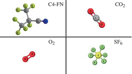
The properties of the gases of interest are shown in Table I. The boiling point of C4-FN is −4.7 °C at 0.1 MPa, which is significantly higher than that of SF6. For this reason, it must be mixed with a buffer gas, such as CO2, to allow for low-temperature applications. All the gases presently of interest are nontoxic, non-flammable and have no ozone depletion potential (ODP) [10, 17, 20].
| Molecular weight (g/mol) | Density (kg/m3) at 0.1 MPa | Boiling point/°C | GWP100 | Electric strength/p.u. at 0.1 MPa | |
|---|---|---|---|---|---|
| SF6 | 146 | 6.17 | −64a | 24 300 | 1 |
| CO2 | 44 | 1.98 | −78.5a | 1 | ≈0.3 |
| C4-FN | 195 | 7.9 | −4.7 | 2750 | ≈2 |
| O2 | 32 | 1.43 | −182.96 | 0 | ≈0.3 |
| N2 | 14 | 1.25 | −195.8 | 0 | ≈0.3 |
- a Sublimation point.
The GWP100 of C4-FN is 2750, which is significantly lower than that of SF6 (24300) and allows a reduction of the CO2 equivalent by 99% for the C4-FN gas mixtures relevant for use in electrical equipment [10, 29]. The electric withstand of pure C4-FN is about twice that of SF6 at a reference pressure of 0.1 MPa, see e.g., the overview [30]. CO2 has a dielectric withstand only slightly lower than air [17, 20, 30]. O2 admixture of 10%–20% can increase the electric strength of the gas slightly by about 6%–10% [31] and reduces the formation of gaseous and solid decomposition products in high current switching applications [32, 33]. The O2 concentrations typically used are in the range of mole fractions of 10%…30% [17, 20, 22, 27]. For very low temperature applications of −50°C only CO2/O2 mixtures are used [17, 19, 20]. Some physical properties of the mixtures of interest are given in Table II. For a filling pressure of about 700 kPa and 3.5 mol% C4-FN in CO2/O2 an electric strength comparable to SF6 at a GWP100 of about 293 is achieved. This mixture can be used down to −30 °C and is favored for low-temperature CB applications. Further properties of SF6 alternative gases and mixtures are given in Refs [9, 16, 17, 20].
| Cada | pmin/MPab | Tmin/°Cc | GWP100 | D.S.d | |
|---|---|---|---|---|---|
| SF6 | — | 0.43…0.6 | −41…−31 | 24 300 | 0.81…1 |
| CO2 | — | 0.6…1 | ≤ −50 | 1 | 0.4…0.7 |
| CO2/C4-FN and CO2/C4-FN/O2 | ≈3.5…6 | 0.7…0.9 | −30…−25 | 293…500 | ≈0.87…0.96 |
- a Concentration of admixture is in mole % referred to the gas mixture.
- b Typical lock out pressure range.
- c Minimum operating temperature for pmin.
- d Electric strength compared to SF6 at 0.55 MPa.
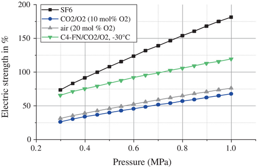
The electric insulation for different gases and mixtures was investigated by determination of fundamental properties as the ionization and attachment rates, e.g., [30, 34-38], or by breakdown tests in simplified electrode geometries, e.g., [24, 25, 30]. A comparison of pressure dependence of electric strength for various gases and mixtures under switchgear conditions is shown in Figure 3. A C4-FN/CO2/O2 gas mixture defined for a minimum operating temperature of −30 °C and a filling pressure of 700 kPa (@ 20 °C) has a similar electric strength as SF6 at 450 kPa. Thus, for switchgear using SF6 alternative gas mixture a slight increase of pressure compared to SF6 is necessary to obtain similar insulation performance. CO2 and air cannot reach the insulation performance of SF6 at 450 kPa even when extrapolated to higher pressures well above 1 MPa [39, 40]. For such gases the equipment needs to be increased in size for lowering of electric fields.
Arcing in CBs, as it occurs during switching operations, leads to partial gas decomposition, which needs to be considered in the properties of the gas mixture after arcing such as the electric strength. Gas compositions and properties of gas mixtures under arcing are addressed in various overviews, e.g., [9, 17, 20, 41, 42]. In C4-FN/CO2/O2 mixtures typical remaining products in a switchgear after arcing are C4-FN, CO2, N2, O2, CF4, and very low amounts of CO, which is efficiently reduced by the addition of O2. Note that decomposition of C4-FN molecule occurs only in the very small fraction of the gas which is in direct contact with the arc. This small change in composition has only a negligible effect on the insulation strengths at operating conditions [9, 17, 20]. As shown in [17, 20], gas decomposition of C4-FN does not affect the lifetime of the CB for typical C4-FN concentrations and switchgear volumes.
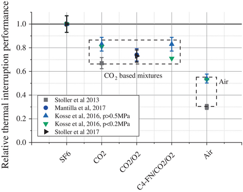
The switching performance of SF6 alternative gas mixtures was investigated in various studies, see for overviews [17, 20]. This was done by investigation of the short-line-fault interruption, so called thermal interruption capability but also on the electric recovery after arcing. Figure 4 shows a comparison of the thermal interruption capability of CO2-based gas mixtures and air to SF6. The performance of CO2-based gas mixtures is slightly below SF6 and reaches about 67% to 87% of the SF6 performance. This seems not to depend significantly on the addition of fluorinated compounds, which can likely be explained by the low percentage added, as was explained in Ref. [43].
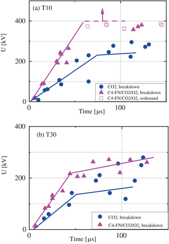
A recent experimental benchmark study using a puffer CB is investigating the differences between various SF6 alternative gas mixtures under the same conditions [44-46]. First results show that the interruption limits measured for the C4-FN/CO2/O2 mixture with 5% C4-FN content [46-48] is higher than that of pure CO2. The differences occurred during the first few microseconds after current zero (CZ) and without measurable post-arc current, indicating a dielectric breakdown mechanism. This shows that fluorinated additives have a large impact on the electric strength even at low amounts and in high-temperature gas. It agrees with the positive synergy observed in breakdown tests for small additive concentrations of only a few percent [30]. This was also observed in previous switching experiments; see Fig. 5, where the dielectric recovery after arcing currents of T10 and T30 for a 31.5 kA rated short circuit current was determined in a self-blast CB over a time range of up to 1 ms after CZ. A significant effect resulted from C4-FN addition (compared to CO2/O2) in the first few 100 μs after CZ. This is not only valid for short circuit current switching but also for load current switching, like capacitive and shunt reactor current switching [48, 49].
2.2 SF6 alternative HV CB using vacuum CB
Recently also vacuum CBs (VCBs) with air insulation became available for sub-transmission ratings [50-53]. This is a new field of application for VCB, which are usually dominant in MV distribution applications. The feasibility of application to higher voltage, e.g., for transmission ratings, needs to be shown. There are technical and economic challenges when going to higher voltages with VCB and air insulation. Due to the nonlinear voltage-contact distance relation, large distances and/or multiple gaps are needed when going, e.g., to 245 kV or higher ratings [17, 54]. This increases the costs of the CB and economy of scale might not apply easily due to lower production numbers in HV transmission. The total CO2 equivalent of gas CB solution compared to VCB/air solutions needs to be considered by performing life cycle assessments, e.g., [10, 19, 22, 55]. Due to the significantly lower insulation performance (Fig. 3), air insulation requires larger equipment size and higher fill pressures compared to the more compact designs possible with C4-FN at lower pressures. The poor electric insulation of air compared to C4-FN-based mixtures will increase the carbon footprint of such solutions even when considering the lower GWP100 of the insulation gas.
2.3 Recent and ongoing product developments
Over the last years roadmaps for CBs using SF6 alternatives were shown by the leading manufacturers [56-58], and products entered the market, e.g., see Refs [19, 48, 52, 58-63]. Hitachi Energy launched CO2/O2- and C4-FN/CO2/O2-based products under the brand ‘EconiQ™’; they are available for 72.5 and 145 kV LTB and GIS, 420 kV GIS, DTB and gas-insulated lines (GIL) at the time of this writing. Also, a “retrofill” solution for 420 kV GIL was launched. In 2024 further products for 420 kV and higher ratings up to 550 kV will be addressed. During the next few years additional products, including for ratings of 245 kV are planned. General Electric (GE) launched C4-FN/CO2/O2-based products under the brand g3 for 420 kV GIS and 145 kV DTB in 2023. Products for 72.5 kV DTB and 245 kV GIS and LTB are planned for 2024. For 2025 170 kV GIS, 245 kV DTB and 420 kV LTB have been announced. In 2026 ratings of 362 and 550 kV DTB and LTB will be addressed. Siemens Energy has available circuit breakers with ratings up to 145 kV that use vacuum circuit breakers and air insulation. Higher ratings are under development. The use of CO2/O2 has been discussed by Toshiba [63] but no product is currently available. For 72/84 kV ratings Toshiba developed a VCB/air GIS which was successfully tested and energized in a pilot installation in 2023 [52]. Hyundai Electric mentioned that it successfully developed 170 kV, 50 kA GIS in 2021 using a C4-FN/CO2 mixture and that development of a 145 kV GIS with air and vacuum circuit breakers is ongoing [64].
3 High Voltage Switchgear Reliability
HV switchgear is composed of different operating devices, including circuit breakers, disconnectors, earthing switches, voltage transformers, and current transformers. Like any other electro-mechanical device, switchgear components are prone to degradation, which can occur due wear and aging as a function of their operation and environmental conditions.
According to CIGRE [65], switchgear malfunctions are classified as ‘minor’ and ‘major’ failures. Major failures cause the cessation of one or more of the fundamental functions of switchgear, resulting in an immediate change in the system operating conditions. In contrast, when a minor failure takes place, the HV equipment is still able to operate, although not under normal conditions.
Circuit-breakers are key components of power transmission and distribution systems; therefore, most of the monitoring systems applied on HV switchgear are usually dedicated to this device. As described by CIGRE [66], maintenance methods can be divided into time-based maintenance (TBM), condition-based maintenance (CBM) and reliability-centered maintenance (RCM) [11].
The development of reliable and simple condition monitoring methods, which can allow the implementation of CBM and RCM, offers a clear opportunity for maintenance improvement. However, such maintenance services need diagnostic and prognostic models able to estimate the probability of failure and/or remaining useful life (RUL) of the operating power grid (PG) assets.
Implementation of algorithms for the detection of failures and lifetime estimation depends on the availability of measurement data from the considered PG assets. Once the data is available, it needs to be correlated and linked through diagnostic/prognostic models for failure detection or prediction [11]. Methods for diagnostics of switchgear working conditions, as well as prognostic of its remaining useful life are summarized in the next sections.
3.1 High voltage switchgear health diagnostics
Traditional circuit-breaker condition assessment methods are based on the measurement of specific parameters, such as dielectric gas density, close/open operation time, contact speed, maximum coil current, and then comparing the monitoring data with the manufacturer specifications.
Independent of its manufacturer, some specific HV switchgear malfunctions take place more often in the field. For instance, a dielectric gas leak is the main minor failure root cause of HV switchgear, as reported by CIGRE [66]. Therefore, dielectric gas monitoring is widely applied [67].
In contrast, some failures are extremely rare, such as excessive wear of circuit breaker interrupter contacts and nozzles. Since HV switchgear is a protection device, its design and tests are developed for more severe stress conditions than the ones normally occurring in the field. Nonetheless, there are special cases where very high switching frequencies are required, for which wear monitoring systems are strongly recommended. A widely used method for contacts' wear estimation is based on the total charge transferred through the main contacts and the energy accumulated over years of operation [68].
Diagnostics focused on vibration signals have dominated the research in the field of circuit breaker monitoring during the last years [11], while extraction of new features have been developed for the improvement of the existing online condition monitoring solutions, some of them described in the following sub-sections.
3.1.1 Partial discharge (PD) monitoring
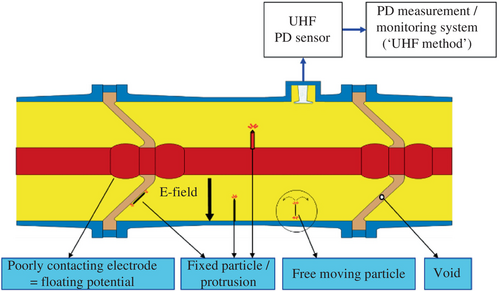
In general, partial discharge (PD) inspections are used in switchgear commissioning to check the HV equipment working conditions, whereas online PD monitoring is commonly focused on GIS applications. Online PD monitoring systems were introduced already in the late 1990s and are essentially based on ultra-high frequency (UHF) technology. UHF online PD monitoring systems for GIS detect PDs during the operation of the GIS. PDs may precede a breakdown of the insulation. In an ideal case, the user can isolate the affected section and initiate diagnostics and repairs before a flashover can occur. According to CIGRE statistics, about 55% of all dielectric breakdowns in GIS could, in principle, be preceded by PDs [69].
On-line PD monitoring systems detect UHF broadband signals excited by gas discharges at free moving particles, protrusions on enclosure or on live parts, voids, delamination's, or floating parts (see Fig. 6). PD sensors, i.e., UHF broadband antennas, pick up PD signals inside the enclosure or at openings such as viewports. After amplification and detection/rectification, a data acquisition unit records, analyzes and stores PD events and alerts the user in case of a significant signal. Noise gating and detection in the UHF band can be used to reduce interference from external sources. Signal processing and analysis may include expert systems for recognition of the PD signal characteristic and its source. The sensitivity of the systems is usually verified by a check recommended by a CIGRE working group [70] based on comparison to the UHF signal produced by an actual defect generating 5 pC apparent charge, measured according to IEC60270. The risk assessment procedure was developed and described by CIGRE [71].
In addition, in terms of data analysis, several solutions have been proposed with focus on malfunction classification, such as artificial neural networks (ANN), support vector machines (SVM), decision function classifiers and fuzzy-logic, as summarized by Khan et al. [72].
The detection sensitivity and prevention rate together with the nature of PD activity seem to justify PD monitoring systems only for critical installations with extremely high outage cost [73]. Nevertheless, the state-of-the-art of PD monitoring systems is continually changing. An increased prevention rate of future systems and more cost-effective electronic components for detection and distributed processing may change the situation. Currently, despite the wide diversity of PD monitoring solutions available in the market, development of more precise data analytics methods is still an important investigation topic. CIGRE working group D1-66 is currently preparing a technical brochure about requirements for UHF PD monitoring systems for gas-insulated systems.
3.1.2 Operating mechanism monitoring
Permanently installed transducers in the operating mechanism can be very advantageous due to the criticality of this device to the HV switchgear operation. Basically, the monitoring system records the position of the contact versus time for every switching operation, while a ‘fingerprint’ concept is applied for diagnostics [67].
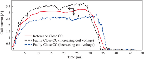
Diagnostic of trip and close coil current is a traditional circuit breaker monitoring method. In the literature, degradation of the coil resistance, increased friction and voltage source fluctuations are some of the malfunctions that can be properly detected by monitoring [74].
Recent publications [11] reported new coil current features that can be associated with failure modes, increasing the malfunction detectability, which can be extracted from coil current profile shifting. For example, comparing with the reference coil current profile, a too high voltage would lead the coil current to increase, while the pulse duration would be reduced, as shown in Fig. 7.
HV circuit breaker travel curve measurement is also a common diagnostic approach. It is performed during routine tests and inspections for condition assessment, after which the travel transducer is disassembled. Some usually evaluated travel curve features are the operation speed, total travel, timing and contact separation/touch.
During the last few years, research has focused on a deeper analysis of the travel curves, aiming to identify new features that can be associated with failure modes, and make the circuit breaker health diagnostic more accurate. Schematically shown in Fig. 8, the overtravel is one of such features. The overtravel ensures latching by closing, whereas its monitoring can give precise information about the latching system condition [76].
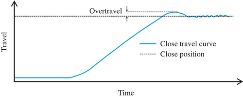
Another important travel curve feature is the rebound, which is the distance traveled by the contacts beyond the final resting position after returning from overtravel. Monitoring of this feature can provide useful information about the operating mechanism damper performance [67].
Extraction of the referred features, and others reported in Ref. [11], can just be possible with the application of monitoring sensors with the necessary measurement precision, as well as data acquisition systems with proper time resolution. In addition, feature extraction might demand the application of sophisticated data analysis algorithms, to be executed locally or in cloud-based processing solutions.
3.1.3 Vibration monitoring
Vibration monitoring can be applied to any mechanical operating mechanism of a HV switchgear, revealing failures in different mechanical components. In addition, this method is not invasive and allows real-time evaluation of the switchgear conditions [77].
The complexity involved in the vibration signal is the main challenge for its analysis and interpretation, so that a reliable association can be obtained between the signal and specific failure modes. In order to clearly detect signatures in the vibration signal that can be associated with malfunctions, measurement resolution on the millisecond scale is necessary. Moreover, HV switchgear vibration is a highly nonlinear and non-stationary signal, which can make the extraction of features very challenging.
Different methods have been proposed in the literature to extract useful information from circuit breaker vibration signals. Multi-scale decomposition is the most widely applied method, which includes empirical mode decomposition (EMD), empirical wavelet transform (EWT), wavelet packet transform (WPT), variational mode decomposition (VMD) and others [11]. Subsequently, the processed signal can be transformed into several intrinsic mode functions, which normally demand considerable computing power, usually not available in local processing units of smart sensors.
A cloud-based solution could solve the high data processing capability issues [78]; however, there might be limitations in the application of battery-powered wireless sensors due to the high battery consumption for relatively big data transmission. Recently, a simplified but reliable vibration feature extraction method has been proposed. According to this concept, global or partial signal characteristics and physics-based features are directly extracted from the signal in the time domain, drastically reducing the need for computer processing power [79].
3.2 High voltage switchgear health prognostics
Beyond the state of health of a piece of switchgear, which gives a picture of its working condition, the prognostic of its remaining useful life (RUL) can also be estimated. It allows proper long-term planning of operation and maintenance of the considered assets.
Different prognostic concepts have been proposed in the literature, with a wide field of application. The concepts can be classified as physics-based, data-driven and hybrid methods. The selection of the method is strongly associated with the available information about the evaluated asset and its working conditions.
3.2.1 Data-driven methods
RUL is normally estimated in the industry by ANN and time series-based methods, such as Markov models [80, 81]. Statistical approaches can also be used for RUL estimation, usually in combination with other data-driven or physics-based methods, as afterward described in the sub-section dedicated to hybrid methods.
Markov models determine the necessary time for a system to transit from its current state to a state of failure, based on the stochastic multi-state Markov process. According to this process, the system can assume only one state at any time, for which there are just two possibilities: either the system stays in the same state, or changes to another state with some probability [80]. These models assume that the system depends only on its present state, being independent of the past [82].
Different commercial Markov-based software for switchgear RUL estimation are available in the market, whereas specific publications can also be found in the literature, such as the modeling of the overall evolution state of switchgear [83, 84]. An alternative method is the autoregressive integrated moving average (ARIMA) time series, which in contrast to the Markov process, considers past values in its regression model [81].
ANN are currently the most widely applied data-driven method for prognostics, for which a large variety of different architectures is available [80]. The working principle of this data-driven method is based on a network of artificial neurons that learns a way of estimating the degradation or working conditions of one or more asset components, reacting to the associated monitoring data [85]. ANN are based on a mathematical representation of the asset developed by data collection.
Regarding the specific application to switchgear, ANN methods have been mainly developed with a focus on analysis of vibration monitoring data generated during the asset operation. However, its industrial application is currently very limited due to lack of robustness of these methods, which normally depend on high computing power and large training datasets [11].
3.2.2 Physics-based methods
Data-driven methods normally need a relatively large amount of data for RUL estimation of an asset. In contrast, since physics-based methods are developed using working conditions and degradation modeling of the assets to be evaluated, a smaller dataset is usually required to provide reliable prognostic results.
Physics-based methods allow estimating asset physical variables as a function of time and/or its number of operations. Furthermore, asset working conditions can be evaluated from a comparison between a specific monitoring parameter, such as the coil current of a circuit breaker spring drive actuator, and the simulation of the same parameter by a model that considers its associated variables under normal conditions (coil resistance, voltage source, mechanism friction, etc.). From this comparison, the variable values of an assessed component can be deduced, giving indications of an eventual failure. This method is commonly named ‘digital twin’ since the physics-based model mirrors the evaluated asset [86].
Understanding the physics of failure and its associated degradation mechanism is crucial for the application of physics-based methods. Well-known degradation processes, such as battery aging, can be properly represented by such models [87]. However, direct application of physical models for degradation prognostics can be very challenging for complex systems like switchgear. In the literature, different degradation models have been proposed, which could be further developed for implementation in condition assessment [88]. Recently, the development of a digital twin system of ‘intelligent switching substation’ has been reported, based on real-time measurement data and 3D digital models in a virtual space. Applying this tool, the aim is to perform remote inspections, online diagnostics, and full lifecycle management [89].
Physics-based degradation models might contain unknown parameters, whereas the quality of the diagnostic provided by digital twins also strongly depends on the accuracy of the monitoring data. Moreover, specific knowledge of the physics involved in HV switchgear critical components is normally just owned by their respective manufacturers, usually thanks to design knowledge, long-term testing and simulations [12].
3.2.3 Hybrid methods
In a complex system, several degradation mechanisms may develop in parallel with different coupled effects, while physical models are normally available only for a subset of possible effects of an asset degradation process. Hybrid approaches have been proposed to compensate for such limitations, in addition to the lack of a large amount of monitoring data, normally required for the application of data-driven methods.
Physics-induced machine learning has been proposed as a promising method to support the understanding of an asset working condition. According to this method, prior knowledge is included in the model, improving its performance and interpretability, while also reducing the need for a large training dataset. There are variations of this approach, such as physics-informed neural networks (PINN), physics-guided neural networks, semantic-based regularization, and integration of logic rules [12].
In order to improve and calibrate data-driven or physics-based prognostic models, statistics-based algorithms can be applied. These methods are usually based on the Bayesian inference, which allows uncertainty to be incorporated into the adopted model [85]. Bayesian methods assume an uncertain parameter as a random variable with a probability distribution based on prior knowledge. Once new information is available, this probability distribution is updated. Applying this concept, asset monitoring data is used to estimate and update unknown parameters of models in the form of a probability density function (PDF).
Some alternative approaches to the Bayesian method are the Particle Filter (PF) and Kalman Filter (KF). Basically, PF applies the same concept used by the Bayesian method, with the only difference regarding the way of updating distributions and generating samples [85]. In contrast, KF can filter noisy time domain signals of linear systems, estimating unknown model variables in two steps: prediction and update [90]. A variant of this method, called Extended Kalman Filter (EKF), can be used for nonlinear systems. For instance, KF has been applied in combination with ARIMA by Qiao et al. [91] for prediction of GIS busbar electrical contact overheating faults.
Recently, a method has been proposed to predict RUL and reliability of a system by physical models in the framework of stochastic processes, applying the Fokker-Planck equation in combination with a Bayesian approach. Though understanding the physics of failure and its preceding degradation mechanisms are needed for application of this method, incomplete available data, and the presence of noise in the monitoring signals of complex systems can be compensated by this statistical physics approach [92].
It is important to state that there is no ideal prognostic method for all applications. The selection of an appropriated approach depends on the complexity of the system to be assessed, availability of monitoring data and understanding of the physics involved.
4 HVDC Switchgear
4.1 Offshore wind market development
Electrical grids are undergoing significant changes as a result of booming trends in energy transition. Integrating more energy from renewable sources to replace fossil-based generation is one of the transformations which has drawn much attention in recent years. Monitoring the developments of offshore wind farms during the past years and the plans that different countries have already set as their target for the decade, shows how different transmission system operators (TSO) are reacting to these energy transition initiatives. Focusing on major TSOs in Europe, a trend toward integration of more offshore wind parks along with the interconnections between different nations can be observed. Advanced transmission technologies, such as high-voltage direct current (HVDC), are playing a defining role in the realization of the abovementioned plans.
HVDC technology has been in use for many years for point-to-point applications. However, the integration of offshore wind farms has revitalized interest in multi-terminal and meshed HVDC transmission grids. TenneT, a German TSO, already presented a 6 GW hub to accelerate the expansion of offshore generation in 2022 and named it ‘wind power booster’. The wind power booster enables sustainable expansion of the grid in the North Sea and coastal regions. It is an initial step towards a meshed HVDC grid in the North Sea and the neighboring countries with the ultimate goal of reaching climate targets through a secure power supply [93].
Similarly, in the Baltic Sea, 50 Hz and Energinet, German and Danish TSOs, are collaborating on the Bornholm Energy Island (BEI) project to connect multiple wind farms and enable cross-border energy transmission trade. The plan is to make Bornholm Island a power hub and to transmit the power through 525 kV HVDC land and sea cables [94].
The market evolution in the offshore HVDC grid is evidenced by the aforementioned initiatives and plans, which are supported by extensive research from various universities and institutes. EU-funded projects such as InterOPERA and PROMOTioN are examples of such technology development and EU investment in this field [95, 96].
These initiatives not only call for new sets of policies and regulations but also advanced transmission technologies, such as effective DC grid control, protection schemes, HVDC gas-insulated systems, and HVDC circuit-breakers. To ensure the success and reliability of such HVDC grids, effective grid protection and flexible control infrastructure are essential.
4.2 High-voltage direct current gas-insulated switchgear
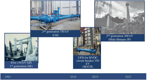
The potential of gas-insulated systems for HVDC applications was recognized and studied in the 1960s following the first installation in 1983. Based on an increasing demand for space-saving and reliable HVDC solutions for both submarine and land applications, the new and second generation of even more compact gas-insulated systems for HVDC applications are under development worldwide (Fig. 9) [97, 98].
Using modern multi-physics simulation tools, the analysis of temperature and electrical field distribution is possible today with high accuracy, taking the following parameters into consideration: temperature- and electric-field-dependent characteristics of the insulating materials, accumulation of space and surface charges and the superposition of DC and impulse voltages. New DC insulators for HVDC gas-insulated systems were designed by geometrical optimization and insertion of a current collector. With additional modifications of interface components, like cable termination, and with the development of special current and voltage transformers, it is now possible to use gas-insulated HVDC systems for both onshore and offshore applications. In Japan, second generation GIS were developed in the 2010s. In 2020 two new HVDC systems were installed in Japan. It is noteworthy that a medium-voltage HVDC GIS was also used here for the first time as return busbar at a rated voltage of 10 kV [99]. In Germany, the first offshore HVDC GIS was put into operation at the same time [100].
Just as in AC power systems, all HVDC GIS technology spans several switchgear components, e.g., bus ducts and high voltage DC conductors, disconnect- and earthing switches, bushings and cable terminations, current and voltage transducers, and surge arresters. Encapsulated surge arresters ensure protection from overvoltage. Their active parts consist of metal oxide varistors with a strongly nonlinear current–voltage characteristic. Gas-insulated RC (resistive-capacitive) voltage dividers map high-voltage linearly over a frequency range from DC up to 30 kHz [101]. They are designed also for an optimum transient behavior. Current detection relies on the zero-flux measurement principle for rated currents up to 5000 A [102]. At the core of the switchgear assemblies is the disconnector. Together with the earthing switches on either side of the isolating gap, the disconnector ensures the safe insulation and earthing of de-energized circuits. These components can be applied in various HVDC applications such as DC pole equipment in HVDC converter stations, gas-insulated transmission lines, cable to overhead line transition stations, and HVDC circuit-breaker components.
Dimensioning of HVDC GIS requires knowledge of electric field distributions occurring in the case of DC conditions. Starting from a capacitive field distribution at the moment of energization with DC voltage, the electric field distribution continuously evolves over time. This field transition depends on the surface and bulk currents in the solid insulation, defined by the strongly temperature-dependent volume conductivity as well as ionic currents in the gas [103]. It results in surface charging, particularly of the solid–gas interface of insulator surfaces, and space charge accumulation in the solid insulation, until the steady state under DC voltage stress is reached [104].
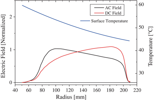
Since the operating currents cause an inhomogeneous temperature distribution between conductor and enclosure, the solid insulator experiences a high-temperature gradient. The conductivity of the material varies by orders of magnitude in the relevant temperature range. Hence, the conductivity increases in the vicinity of the heated conductor, usually resulting in an enhanced electric field strength in the colder regions of the insulation [105]. One approach to avoid charge accumulation is to make the resistive field distribution equal or similar to the capacitive field distribution by design and proper choice of material properties (Fig. 10). The temperature gradient across the insulation considered for the simulation is equal to the worst case under service conditions and maximum continuous current [106].
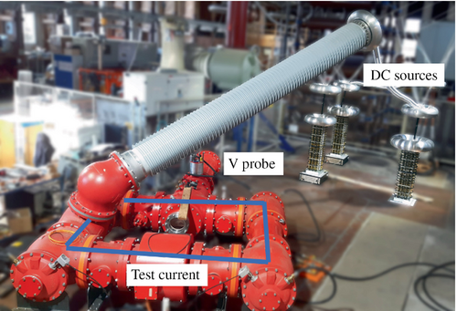
One important question is in any case: How can the simulated field distribution be verified and how close are the simulated field distributions to the real ones [107]? Due to the complexity of the—often nonlinear—physical effects at hand in the gas and solid insulation, it is necessary to validate multiphysics finite element modeling (FEM) approaches used to design DC insulation by direct monitoring of the electric field or surface potential at the solid–gas interface during the transition from capacitive to resistive field [108]. A real size measurement device is shown in Fig. 11. The system is currently being further developed at the University of Stuttgart/Germany [109].
The testing requirements for gas-insulated HVDC systems are currently not standardized. The physical basis for HVDC applications was described by CIGRE already in 2012 [110]. Based on these findings, together with new experiences of the manufacturers, recommendations have been elaborated in CIGRE JWG D1/B3.57 [105]. The IEC is currently working on the implementation in international technical specifications (IEC 62271 series). Besides DC withstand voltage tests, composite voltage tests with lightning impulse and switching impulse voltage, superimposed to DC voltage, must be conducted after a defined period of DC pre-stress. Additional electric and thermo-electric tests must be performed to consider the special aspect of DC voltage in terms of the electric field distribution of insulators, influenced by the accumulation of electrical charge carriers and the operation-related inhomogeneous temperature distribution, as mentioned before. Electro-thermal tests are of high importance for HVDC GIS, due to the temperature-dependent field transition.
- The components included in the test object
- Installation and commissioning procedure
- As well as the dielectric, thermal and mechanical stresses applied in the test itself.
- Testing with representative stresses for real-life operation
- Inclusion of monitoring and diagnostics during the test
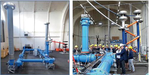
The first prototype installation test worldwide for an HVDC GIS is shown Fig. 12 [111]. The test procedure and results for an HVDC GIL are described in [112].
4.3 HVDC circuit-breakers
HVDC circuit-breakers are essential for the uninterrupted operation of HVDC grids when grid faults occur. They enable the creation of multi-terminal/meshed HVDC grids to transfer large-scale offshore wind energy in a reliable and efficient way. These grids ultimately enable a common energy market through cross-border interconnections. Compared to AC fault current interruption, DC fault current interruption is challenging because of the following reasons [114]:
There is no natural current zero in DC systems, unlike in AC systems. The fault current in HVDC systems rises rapidly, limited only by the resistance in the current path, whereas in AC systems, the peak value is determined mainly by the inductance of the conductors. Therefore, very high fault currents can emerge in a range of milliseconds. Thus, HVDC circuit-breakers need to act very fast, around 10 times faster than AC circuit-breakers to clear a fault current [115]. To interrupt fault current, HVDC circuit-breakers need to quickly generate and sustain a counter voltage (transient interruption voltage—TIV) that exceeds the system voltage [116, 117].
Compared with AC fault current interruption, the absence of naturally recurring zero-crossings in a DC fault current requires alternative solutions, such as using power electronic switches or creating artificial zero-crossings if mechanical switches are used for interruption [118-120].
For application in energy transmission systems, additional requirements include low on-state losses and a high current carrying capability. Moreover, advanced functions proposed in addition to the basic functionality of fault current interruption can be used in HVDC grids to improve the performance of the protection system [121, 122]. The HVDC circuit-breaker is no longer just a mechanical contact system, but rather a system of components arranged in multiple current branches to which current is commutated in a controlled manner to achieve DC interruption [126-130]. HVDC circuit-breakers typically consists of at least three parallel branches to carry a load current (normal current branch), to commutate current during interruption (commutation/main breaker branch), and to absorb the associated energy (energy absorption branch), see Fig. 13 [116, 117, 131-134]. In addition, a residual current breaker is typically required to provide isolation and prevent overloading of the energy absorption elements. A series line inductor may be needed in order to limit the rate-of-rise and the peak of the current to achieve successful interruption.

Many different technologies have been proposed to generate and to maintain a counter voltage [135]. For voltages up to about 10 kV, a counter arc voltage can be achieved by elongating, cooling and splitting the arc. In the case of HVDC CBs, the counter voltage is created by forcing the current into a high-impedance path as described in Refs [133, 136]. Depending on the technologies used for interrupting a current, HVDC circuit-breakers can be broadly grouped into mechanical (or resonance current injection), hybrid and pure power electronic types, each having their advantages and disadvantages in terms of operation speed, on-state loss, complexity, and cost [137, 138].
Mechanical HVDC circuit-breakers superpose a high-frequency alternating current provided by a resonant circuit on the DC fault current to create zero-crossings, and consequently use an AC breaker for current interruption. There are two sub-types, namely passive and active resonance current injection, depending on if the resonant current is passively or actively injected to the load current branch [132, 136]. Existing mechanical HVDC circuit-breakers using passive resonance current injection have reached rated currents of 5.3 kA with interruption within 20 ms [139]. Recent development work on active resonance breakers demonstrates that commutation can be achieved within 5∼8 ms with breaking capability of 16 kA [119, 120].
Another current-injection-based design is based on thyristor-controlled current injection. In the VSC-assisted resonant current injection (VARC) design, the active injection circuit consists of a VSC that generates an HF current that has an increasing amplitude [140]. The oscillation is excited by a full-bridge converter installed in series with an L-C circuit.
Power electronic HVDC circuit breakers have two parallel branches [141]. The main current branch carries the continuous current during normal operation, typically through a large number of power semiconductors that are connected in series and in parallel. In the case of an intended turn-off, all power semiconductors are turned off, and the current is commutated into the high-impedance energy absorption device connected in parallel. As no mechanical switches are necessary, this type of circuit breaker is able to quickly commutate current, typically in microseconds. However, because the load current flows through power semiconductors, the electrical losses are usually judged to be too high for transmission system applications [132, 136].
Hybrid HVDC circuit-breakers use a low-loss load current branch and a commutation branch consisting of power electronic switches. Typical opening times range from 2 to 3 ms [118, 142-148]. The rated breaking current capability varies from 9, 16 to 25 kA [118, 143, 149]. Experiments and applications have shown that the capabilities of this breaker type could fulfill HVDC system requirements [132, 136, 150].
An innovative commercial solution of a hybrid HVDC circuit-breaker was published in 2011 [118], utilizing field-proven components including semiconductors and GIS disconnectors. The development of the hybrid HVDC circuit breaker continued through an intensive design and testing program, which resulted into a successful full-scale test of a 350 kV HVDC circuit-breaker in the independent laboratory of KEMA as part of EU-funded PROMOTioN project, see Fig. 14 [96].
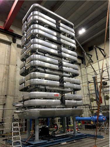
However, similar to HVDC converter stations, hybrid HVDC breakers have a modular designed and a proper test program on a module level has been verified to be sufficient to guarantee the performance of a full-scale breaker. The market overview shows that a common system voltage level is 525 kV for HVDC grids, so the recent product development of a hybrid HVDC breaker is aligned with this level.
Figure 15 shows a single line diagram (SLD) for a hybrid HVDC breaker. It consists of three major units, the load commutation switch (LCS), an ultra-fast disconnector (UFD), and the main breaker (MB). The MB itself is made of several cells which are cascade-connected according to the system voltage level. The LCS and UFD provide a low resistance path for load current during steady-state operation. The control and protection system triggers the operation of the hybrid HVDC breaker, which is initiated by opening the LCS. This forces the conducting current to be commutated to the parallel MB path and upon full commutation, the UFD is opened to isolate the LCS and enable the operation of the MB cells. The MB cells are triggered one by one to fully commutate the current to the nonlinear resistors of each cell where the fault energy will finally be absorbed.

Both LCS and MB are semiconductor-based switches with microsecond operation time, while the UFD is driven by a Thomson coil actuator operating in a few millisecond range. The overall breaking time is thus around 3 ms, defined from triggering moment up to the instant of commutating the fault current to the nonlinear resistors.
Reliability, availability, maintainability, speed, and cost are five major design factors for hybrid HVDC breakers. The HVDC breaker is continuously conducting the load current so any malfunctioning of this device will impact the overall system performance significantly. As a countermeasure, a hybrid HVDC breaker is designed with proper in-built redundancy and a status monitoring system. Design principles of the Hybrid HVDC breaker units are described in the following:
The LCS is formed by several series- and parallel-connected semiconductor devices. Parallel devices ensure the available current path in case of any failed devices in the LCS; meanwhile, a series of connected devices build up the necessary voltage drop for current commutation into the MB branch. The detailed LCS design is described in Ref. [151].
The MB branch is made by cascade-connected cells each of which is designed for a typical voltage level of 40 kV. As the SLD in Fig. 15 shows, each cell has several series-connected semiconductor devices and nonlinear resistors in parallel. Redundant semiconductors are available in each stacked module to ensure proper failure mode operation, moreover, nonlinear resistors include redundant series and parallel blocks. An additional reliability measure is to include a complete redundant cell.
In series to the LCS, a mechanical gas-insulated UFD is available to realize the high voltage insulation strength during current interruption. The current rating of the UFD is similar to the LCS's to ensure reliable current conduction [152]. The UFD is designed as a dead-tank device to ensure maximum reliability and easy maintenance. This means that all drives are at ground potential and additional power-to-potential components can be avoided.
With respect to hybrid and power electronic HVDC circuit-breakers, there is also an option to implement them with bidirectional or unidirectional current interruption capability [153, 154].
Currently, field experiences had been gained in three VSC-HVDC transmission projects, namely the five-terminal ZhouShan project [155, 156], the three-terminal Nan'ao project [157, 158] and the four-terminal ZhangBei project [159, 160], all of which are located in China. An active current injection HVDC circuit-breaker is applied in the Nan'ao project, while a mechanical and power electronic hybrid HVDC circuit-breaker is used in the Zhoushan system. The ZhangBei project comprises applications of both HVDC circuit-breaker technologies with a total of 16 circuit-breakers.
5 Conclusions
Recent trends in HV switchgear research and development have been presented. In the field of HV AC switchgear, the successful introduction of alternatives to SF6 as insulation and switching medium is an important milestone. For HV switchgear reliability the most important methods for health assessment, monitoring and prognosis have been presented. In the field of HVDC switchgear, the most recent trends and development of HVDC GIS and HVDC CB have been summarized.
Acknowledgments
The authors would like to thank Patrick Stoller from Hitachi Energy Ltd. for inputs and proofreading of the manuscript.
Biographies

Martin Seeger (Non-member) was born in 1961 in Giessen, Germany. He received a diploma and Ph.D. degree in physics from the University of Heidelberg, Germany, in 1987 and 1990, respectively. Since 1993, he has been with ABB Switzerland Ltd., now Hitachi Energy Ltd. in various positions in the field of high-voltage switchgear research and development. Currently, he is a senior principal scientist at the Central European Research Center of Hitachi Energy Ltd. He is a senior member of IEEE and chairman of the gas circle of the Current Zero Club.

Felipe Macedo (Non-member) was born in 1980 in São Paulo, Brazil. He received a diploma in Mechanical Engineering from the Federal University of Santa Catarina (Brazil) in 2005. In 2018, he received the Ph.D. degree in Mechanical Engineering with a focus on Manufacturing and Plasma Physics from ETH Zurich (Switzerland), joining the Corporate Research Center of ABB Switzerland Ltd. in the same year. Since 2023, he has been the head of the GIS Design team of Hitachi Energy Ltd. in Switzerland. He led and developed projects in the fields of R&D, mechanical design, reliability engineering, quality control, industrial engineering and lean manufacturing.

Uwe Riechert (Non-member) is a senior principal engineer and project manager for gas-insulated HVDC and HVAC substations and circuit-breaker at Hitachi Energy in Zurich. He finished his studies in electrical engineering at the Dresden Technical University (TUD) in 1994 and received the Ph.D. Since 1999 he has been with ABB Switzerland, later Hitachi ABB Power Grids and today, Hitachi Energy. He conducted several product development projects in the field of gas-insulated switchgear, high current systems, UHV substations and HVDC gas-insulated systems. Uwe Riechert is a member of national committees in Germany and Switzerland (DKE and CES) and member or convener of different CIGRE and IEC working groups. He is convener of the CIGRE advisory group AG D1.02: High voltage and current testing and diagnostic and of the IEC 17C WG 42: DC gas-insulated switchgear assemblies.

Markus Bujotzek (Non-member) was born in 1979 in Katowice, Poland. He received a diploma in Electrical Engineering from RWTH Aachen University (Germany) in 2006 and the Ph.D. in Electrical Engineering from ETH Zurich (Switzerland) in 2015. From 2006 to 2017 he was with the ABB Corporate Research Center (Switzerland) working in the field of gas circuit breakers and gaseous insulation. In 2017 he has joined the Business Unit High Voltage Products of ABB Switzerland, today, Hitachi Energy. Currently, he is working as global technology manager for circuit breakers.

Arman Hassanpoor (Non-member) is the North-East Asia HVDC representative director and Regional Sales manager in Hitachi Energy Grid Integration since 2022. He was working as HVDC R&D department manager in China from 2017 to 2022 and R&D project manager and technical leader for Hybrid HVDC Breaker technology prior to that in Sweden. He received his Ph.D. from KTH Royal Institute of Technology, Stockholm-Sweden, in 2016 and his MSc from Chalmers University of Technology, Gothenburg-Sweden, in 2011. His research area includes high-power grid-connected converters with the focus on HVDC applications.

Jürgen Häfner (Non-member) is the Technology manager at Hitachi Energy Grid Integration taking care of the HVDC related R&D portfolio since 2017. He joined ABB in Sweden in 1996 and received a Ph.D. in Power Electronics at the Technical University of Berlin, Germany in 1999. In his global role at ABB and nowadays Hitachi Energy, he is responsible for the development of new HVDC converter systems, DC grid solutions and the digitalization of HVDC stations. Prior to that he held various positions as technical lead, R&D project and department manager resulting in numerous patents in the area of optical instrument transformers, HVDC breakers and high-power converters.


