Sonographic localisation of neck lymph nodes using surgical neck level classifications
Abstract
Sonographic imaging of the lymph nodes (LNs) of the neck is used to differentiate between those that are benign or suspicious of malignancy. The size, number and location of suspicious appearing LNs must be documented and reported. Cervical LN location should be described in terms of surgical neck levels. Knowledge of the sonographic differentiation between benign and suspicious appearances of LNs, and surgical neck levels is required, including sonographic landmarks that can be used to correctly locate LNs to a specific neck level.
1 INTRODUCTION
The head and neck accounts for only 20% of the body's volume, however this region contains 40% or approximately 300 of the body's 800 lymph nodes (LNs).1-3 Head and neck cancers typically have a predictable pattern of spread along lymphatic drainage pathways to neck nodal basins.3 The presence of neck LN metastases has a profound effect on the prognosis and management of head and neck cancer patients.4 Ultrasound is often requested for surveillance of neck LNs for head and neck cancer patients. Ultrasound is used to determine the status of neck LNs, which includes whether they appear benign or suspicious of malignancy.5 The number, size and location of sonographically suspicious appearing neck LNs must also be correctly documented. The American Joint Committee on Cancer (AJCC) classifies neck LNs into surgical levels based on their location.6 Sonographic reporting of the surgical neck level in which suspicious appearing LNs are located is required to guide patient management.7 Furthermore, accurate and consistent reporting of the location of suspicious appearing neck LNs is required to allow correlation with computed tomography (CT), 18F-fluro-deoxy-glucose-positron emission tomography CT (FDG-PET-CT), and magnetic resonance (MR) imaging and sonographic needle guidance procedures for biopsy. Familiarity with surgical neck levels, and the sonographic technique to image, classify and localise neck LNs is required.
2 SONOGRAPHIC IMAGING AND APPEARANCE OF LNs
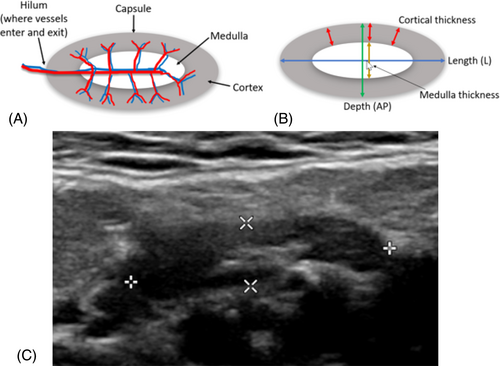
LNs are encapsulated and organised structures, interposed along regional vessels of the lymphovascular system.7 The majority of normal neck LNs are not sonographically visible.5 The term ‘benign’ encapsulates both normal and reactive LNs.8 Benign LNs are typically oval or reniform (kidney) shaped and typically have a long-axis diameter at least two times the short-axis diameter.8 They have a well-defined, regular bordered capsule, and are easily separated from surrounding LNs.8 Sonographically, benign LNs demonstrate an echogenic central medulla, and a relative hypoechoic cortex of generally even thickness throughout.9 The cortical thickness should not be thicker than the medulla.10 The hilum often demonstrates a depression, where vessels enter or exit the LN. The vessels, imaged with colour or power Doppler can be demonstrated to radiate out peripherally and symmetrically through the medulla and cortex7 (Figure 1).
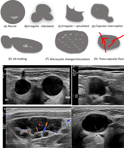
LNs suspicious of malignancy include lymphomatous or metastatic nodes.8 Sonographically, suspicious LNs appear rounded or irregular (lobulated or spiculated) in shape.9 The LN capsule may appear focally or diffusely blurred or interrupted, and LNs can be matted.3 Partial matting results in LNs in contact with one another and complete matting results in LNs unable to be distinguished from each other.11 Diffuse or focal LN echogenicity changes such as hyperechoic deposits or cystic areas within the cortex or medulla are suspicious findings.9 Reticulation (diffuse cortical microcystic changes), can appear as multiple hyperechoic lines or echogenic areas in the cortex and is suggestive of LN malignancy.7 Sonographic loss of the LN medulla and hilum is also suggestive of a suspicious LN.7 Furthermore, evidence of trans-capsular flow on colour or power Doppler, where vessels enter the LN in areas other than the hilum, is considered suspicious9 (Figure 2).
The size of benign neck LNs varies depending on location and the patient's sex.8 LNs in the submandibular region tend to be larger than in other neck regions.11, 12 Various nodal size thresholds have been reported to distinguish benign from suspicious LNs, including measures in the short axis, however, different threshold values result in trade-offs.8 Lower size thresholds result in greater diagnostic sensitivity, but lower specificity and nodal size alone is not used to distinguish benign from malignant LNs.8
2.1 Neck regional anatomy classifications
There are multiple systems that have been used to divide the neck into anatomical regions. These include the 1. Fascial compartment system, 2. Neck triangles and 3. Surgical neck level classifications. It is important that these are appreciated, and not confused by sonographers. The fascial compartment system divides the neck by layers of cervical fascia. The compartments include pharyngeal, carotid, retropharyngeal, pre-vertebral, peri-vertebral and visceral compartments.13 The spaces between neck compartments allow a conduit for the spread of infection. Understanding neck compartments allows prediction of the spread of disease and surgical management.13 A fascial layer of connective tissue immediately deep to the anterior neck skin includes the platysma muscle.14 The platysma is a very thin (1 mm thick) but broad sheet of muscle, called a ‘mimic muscle’ of the lower face and anterior neck.14 Running between the mandible and thorax, blending with the muscles of the face, it plays a role in facial expression and can be underappreciated on sonographic imaging.15 Changes to this muscle may be identified sonographically in those that have previously had aesthetic platysmaplasty surgery14 (Figure 3).
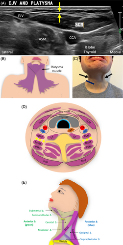
Muscles of the neck can be used as sonographic landmarks and must be appreciated to allow sonographic localisation of suspicious neck LNs. The sternocleidomastoid and trapezius muscles are large landmarks both encircled by the sternocleidomastoid-trapezius (ST) facia.13 Additionally the submandibular salivary glands are important sonographic landmarks surrounded by the ‘submandibular fascia’ which is continuous with the ST fascia.13
Four strap (infrahyoid) muscles of the anterior neck include the: omohyoid, sternohyoid, thyrohyoid and sternothyroid muscles. They can be used to sonographically define surgical neck levels and are named after the structures they connect (named after inferior to superior attachments). The omohyoid muscle extends from the scapula (‘omo’ refers to the scapula) to the hyoid bone; sternohyoid extends from the sternum to the hyoid; thyrohyoid extends from the thyroid cartilage to the hyoid; and the sternothyroid muscle extends from the sternum to thyroid cartilage.13 The neck can also be divided into anterior and posterior triangles for physical assessment of the neck.3, 16 The anterior and posterior triangles are separated by the sternocleidomastoid muscle (SCM).2 These triangles are not used to radiologically localise LNs for surgical planning and must not be confused with surgical neck levels.
3 SURGICAL NECK LEVELS
Surgical removal of malignant neck LNs is an important component of head and neck cancer patient care. Several classification systems have been reported and used over the years to delineate and surgically localise neck LNs, based on surgical landmarks. Originally, a system for classifying neck LNs from CT imaging was developed which divided the neck into seven levels.17 Level VII, deep to the manubrium of the sternum, between the suprasternal notch and the brachiocephalic artery and veins (not seen sonographically) was originally defined but is no longer used.3, 4, 18, 19 It contains superior (upper) mediastinal nodes, which are classified as chest LNs and not neck LNs.3, 4, 18, 19
Surgical neck LN levels are described by the American Academy of Otolaryngology-Head and Neck Surgery (AAO-HNS) and the American Joint Commission on Cancer staging (AJCC).18, 20, 21 The current system for defining neck LNs consists of six levels (I–VI). Neck dissection refers to the removal of suspicious LNs at surgical neck Levels I–V and selective neck dissection refers to removal of suspicious LNs from one or more surgical neck levels, based on the patterns of metastasis of the primary lesion.18, 22 To allow ultrasound and surgical correlation, an imaging nodal-based classification system, using sonographically visible landmarks needed to be developed (Figure 4).
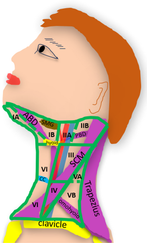
This paper will therefore outline sonographic landmarks used for the six surgical neck levels and their sub-levels, which are outlined in Table 1.
| Neck level | Level borders |
|---|---|
| Superior to inferior (S–I) | |
| Medial/anterior to lateral/posterior (M–L) | |
Level IA Submental |
S-I Body of mandible to inferior border hyoid bone. M-L Midline to medial border of anterior belly digastric muscle |
Level IB Submandibular |
S-I Mandible to inferior border hyoid bone M-L Medial border anterior belly digastric muscle to the posterior border submandibular gland |
Level IIA Upper Jugular—anterior |
S-I Skull base to inferior border hyoid bone level M-L Posterior margin submandibular gland (stylohyoid muscle) to posterior/lateral margin IJV |
Level IIB Upper Jugular—posterior |
S-I Skull base to inferior border hyoid bone level M-L Posterior IJV to the posterior margin SCM |
Level III Middle Jugular |
S-I Inferior border hyoid bone to inferior border cricoid cartilage level M-L Anterior margin CCA/ICA to posterior border SCM |
Level IV Lower Jugular |
S-I Inferior border cricoid cartilage to clavicle M-L Anterior margin CCA to posterior border SCM |
Level VA Superior posterior triangle |
S-I Skull base to inferior border of cricoid cartilage M-L Posterior border SCM to anterior margin trapezius |
Level VB Inferior posterior triangle |
S-I Inferior border cricoid cartilage to clavicle M-L Posterior border SCM to anterior margin trapezius |
Level VI Central (anterior) |
S-I Inferior margin hyoid bone to suprasternal notch M-L Midline to anterior/medial margin CCA/ICA |
- Abbreviations: CCA, common carotid artery, ICA, internal carotid artery; IJV, internal jugular vein, SCM, sternocleidomastoid muscle.
3.1 Anterior neck sonographic landmarks
The surgical neck levels are divided into three main levels from superior to inferior which include: 1. Superior to the hyoid bone, 2. Between the hyoid bone and cricoid cartilage and 3. Inferior to the cricoid cartilage. To sonographically identify surgical neck levels, key sonographic landmarks including the hyoid bone and cricoid cartilage and additionally the thyroid cartilage and tracheal cartilage rings must be appreciated and a systematic approach to imaging from superior to inferior is required. The hyoid bone, an anchor for suprahyoid and infrahyoid muscles, is suspended from the styloid process of the temporal bone by the stylohyoid ligament.23 It moves antero-superiorly when the muscles contract during swallowing.23 The anterior border of the hyoid bone can be demonstrated sonographically in the transverse plane, where the posterior border of the chin meets the neck (Figure 5).
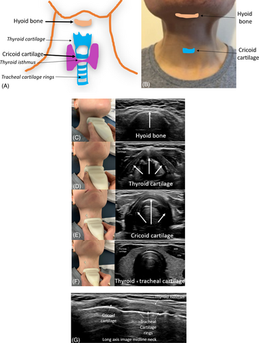
When moving the transducer inferior to the hyoid bone, the triangular shaped thyroid cartilage can be identified anterior to the larynx. Imaging inferior to the thyroid cartilage, the crico-thyroid membrane and the semicircular shaped cricoid cartilage will become sonographically visible. When imaging immediately inferior to the cricoid cartilage, the thyroid isthmus overlying tracheal cartilage rings will become visible sonographically (Video 1).
4 SONOGRAPHIC IMAGING OF NECK LEVELS I TO VI
The relevant anatomy, sonographic boundaries to be used to image and localise neck LNs, sonographic technique and resultant sonographic images of each neck level and sublevels must be appreciated and are outlined below.
4.1 Neck Level I: Submental (IA) and submandibular (IB) levels
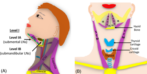
Surgical neck Level I incorporates the area under the chin, superior to the hyoid bone. Level I extends anteriorly to the submental region of the mandible and posteriorly to the posterior border of the submandibular gland (SMG). Level I is subdivided into two levels: the anterior submental (IA) region and the posterior submandibular (IB) region (Figure 6).
4.2 Level IA (submental nodes)
Level IA encapsulates the triangular region under the chin and contains submental LNs. Level IA extends from the mental region of the mandible posteriorly to the hyoid bone. It also extends from the medial margins of the anterior belly of the digastric muscle to midline, superficial to the mylohyoid muscle.17, 18 LNs in this level are prone to metastases from cancers arising from the areas it drains, which includes: the floor of the mouth, anterior oral tongue, anterior mandibular alveolar ridge and lower lip.18, 24 Sonographically, Level IA can be imaged with the neck extended and the transducer placed under the chin in a coronal orientation. This allows the right and left sides of Level IA to be imaged simultaneously. Sonographic landmarks for Level IA include the rami of the mandible, anterior bellies of the digastric muscle, mylohyoid muscle, mandible, platysma muscle and hyoid bone (Figure 7).
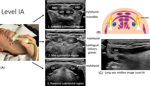
The mylohyoid muscle forms the muscular floor of the mouth and divides it into sublingual and submandibular spaces. The sublingual space sits deep (superior) to the mylohyoid muscle and the submandibular space sits superficial (inferior) to it. Other sonographic landmarks that can be identified deeper include the geniohyoid and genioglossus muscles, tongue, sublingual glands and tonsils. Key structures that run through this level include the lingual nerve, hypoglossal nerve, submandibular duct and facial artery and vein. When LNs are identified in Level IA, a cine can be captured from anterior to posterior to demonstrate the LNs and their relative positions. Scanning is started at the mental region of the mandible and extends posteriorly and inferiorly to where the hyoid bone comes into view (Video 2).
4.3 Level IB (submandibular nodes)
The submandibular group (IB) of LNs is located lateral and posterior to Level IA. Level IB extends from the medial margin of the anterior belly of the digastric muscle, inferomedial to the body of the mandible, to the posterior belly of the digastric muscle and stylohyoid muscle, and laterally to the posterior edge of the SMG.17, 18 As this level does not include tissues posterior to the SMG, it does not include the jugulodigastric (JD) node (Figure 8).
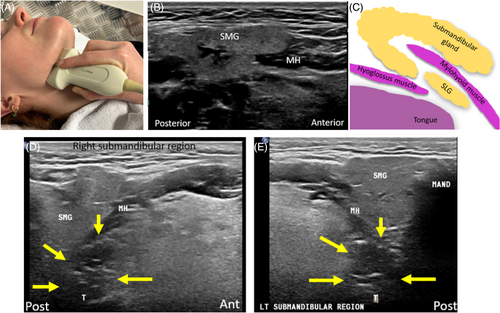
Level IB includes tissues superficial to the mylohyoid muscle extending postero-inferiorly to the level of the hyoid bone. Submandibular (IB) LNs are at greatest risk for metastases from cancers arising from the oral cavity, anterior nasal cavity, soft tissue structures of the midface and the SMG.18, 19 It is important to note that the palatine tonsils, which sit deep to the SMG and appear hypoechoic with echogenic linear stripes, must not be mistaken for suspicious appearing LNs.
5 LEVEL II: UPPER JUGULAR NODES
Level II comprises nodes of the upper jugular group, around the upper third of the internal jugular vein (IJV) and adjacent spinal accessory nerve (CNXI). Level II extends from skull base (jugular fossa) to the inferior border of the hyoid bone.17, 18 The medial (anterior) boundary is the posterior border of the SMG. This level corresponds to the medial (anterior) boundary of the stylohyoid muscle. Level II extends posteriorly to the lateral (posterior) border of the SCM.17, 18 Nodes in Level II are at greatest risk for metastases from cancers arising from the oral cavity, nasal cavity, nasopharynx, oropharynx, hypopharynx, larynx and parotid gland18, 19 (Figure 9).
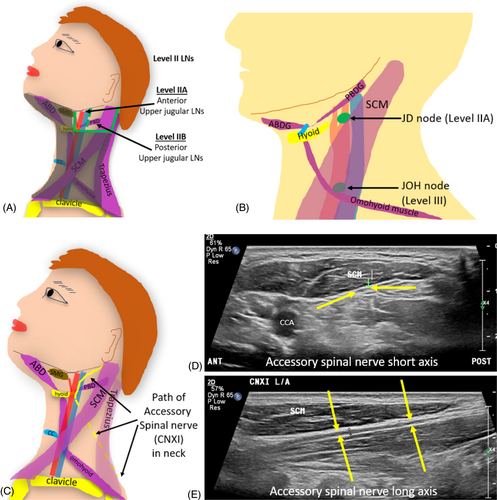
Level II is subdivided into IIA (anterior) and IIB (posterior) nodes by their relationship to the vertically oriented spinal accessory nerve (CNXI).19 CNXI is a cranial neve that has a relatively superficial course through the neck.25 It can be injured during ultrasound guided neck LN biopsies, if its presence is not appreciated. CNXI traverses deep to the posterior digastric muscle and occipital artery and in line with the IJV (either superficial, deep to, or even through the IJV).26 As the IJV is larger and more easily identified sonographically, it is used as a landmark for division of levels IIA and IIB. CNXI is important to be avoided surgically during neck dissection, as it provides motor innervation to the trapezius and SCMs.26
5.1 Level IIA: Anterior upper jugular nodes
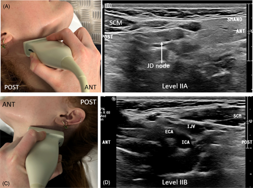
Level IIA LNs are located anterior to the vertical plane defined by CNXI and the posterior border of the IJV.3, 18 They lie posterior to the posterior border of the SMG and anterior, superficial or deep to the IJV, superior to the hyoid bone.17 This includes LNs surrounding the internal carotid artery (ICA) remaining superficial to it.3 LNs deep to the ICA are not included in level II and are classified as retropharyngeal LNs.3 Level IIA includes the JD nodes (also known as sub-digastric LNs) which lie immediately posterior to the posterior border of the SMG, inferior to the posterior belly of the digastric muscle, anterior to the IJV, and is typically the largest of all the neck LNs.5, 12
The upper limit for the short axis of neck LNs is usually 10 mm. However, JD nodes can be larger in size (up to 11 mm is considered within normal limits for the short axis of the JD LN).5 In young cancer-free patients, the long axis size of the JD nodes is commonly above 15 mm.12 Transverse imaging of Level IIA is achieved by placing the transducer inferior and posterior to the angle of the mandible, posterior to the SMG. Static and cine imaging can include the posterior aspect of the SMG, the ICA, ECA and IJV (Figure 10).
5.2 Level IIB: Posterior upper jugular nodes
Level IIB nodes are located posterior to the vertical plane defined by the spinal accessory nerve.18 Sonographically they lie posterior to the IJV and extend to the posterior border of the SCM, superior to the hyoid bone.3, 17 It is important not to get neck LNs (Levels I and II) confused with LNs of the head and face, particularly facial, parotid, mastoid and occipital LNs. Facial LNs sit inferior to the orbit but superior to the inferior mandible and can include buccinator LNs. Occipital LNs sit near the occipital subcutaneous tissues. Parotid LNs sit around and within the parotid gland (including pre-auricular, intraglandular and sub-parotid LNs). Mastoid LNs are retro-auricular in location.20, 24
6 LEVEL III: MIDDLE JUGULAR NODES
Level III includes the middle jugular group of LNs. As their name suggests, they are located around the middle third of the IJV and inferior to Level II.3 Level III extends from the inferior border of the hyoid bone to the inferior border of the cricoid cartilage.17, 18 Level III also extends from the lateral border of the sternohyoid (strap) muscle to the posterior border of the SCM muscle.3, 18 The anterior (medial) margin of the ICA (superiorly) or common carotid artery (CCA) (inferiorly) is used as a sonographic landmark for this level.3, 17 The mid CCA and IJV sits within this level. LNs superficial and deep to the CCA and ICA are included in this level, which is different from level II, where LNs deep to the CCA and ICA were termed retropharyngeal LNs3, 17 (Figure 11).

Middle jugular LNs are at greatest risk for harbouring metastases from cancers arising from the oral cavity, nasopharynx, oropharynx, hypopharynx and larynx.18 The jugulo-omohyoid (JOH) node is the most prominent LN within Level III.5 JOH nodes, also known as ‘Poirier's JOH’ or ‘tongue nodes’ are related to the drainage of the tongue.27 They can sit superficial or deep to the IJV at the level of the intermediate tendon of the omohyoid muscle (between superior and inferior parts of this muscle) where the superior belly of the omohyoid muscle crosses it.5, 18 The phrenic nerve, superficial to the anterior scalene muscle, deep to the deep cervical fascia, is an important structure to appreciate at this level when guiding biopsies of LNs.28
7 LEVEL IV: LOWER JUGULAR NODES
Level IV, containing lower jugular nodes, inferior to Level III, extends from the inferior border of the cricoid cartilage to the clavicular level.18 It extends from the lateral border of the sternohyoid muscle which sonographically aligns with the medial or anterior margin of the CCA, to the posterior border of the SCM muscle.3, 17, 18 Structures located to appreciate when undertaking biopsies at this level include the carotid sheath, thoracic duct, transverse cervical artery and phrenic nerve. Occasionally the lung apices may extend into the inferior aspect of Level IV (Figure 12).

Nodes located within this level are at greatest risk of harbouring metastases from cancers arising from the hypopharynx, cervical oesophagus and larynx18 and includes Virchow's node.19 Virchow's LN, a left supraclavicular LN, is typically located at the site of lymph drainage into the systemic circulation at the junction of the thoracic duct and left subclavian vein.3 Virchow's LN may be involved in head and neck, chest, or abdominal metastatic disease, and it is usually affected on the left side.3, 18 When enlarged, it can potentially compress the phrenic nerve (Video 3).
8 LEVEL V: POSTERIOR TRIANGLE NODES
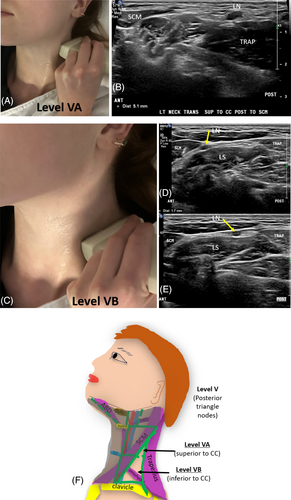
Level V, posterior to the SCM muscle, contains the posterior triangle group of LNs. The anterior boundary of Level V is the posterior border of the SCM muscle. It extends posteriorly to the anterior border of the trapezius muscle.18 Immediately posterior to Levels II–IV, it is demarcated superiorly by the convergence of the SCM and trapezius muscles at the level of the skull base. It extends inferiorly to the level of the clavicle.17, 18 Level V extends along the lower half of CNXI and the transverse cervical artery and is further subdivided into two sublevels: VA and VB by a horizontal plane at the level of the inferior border of the cricoid cartilage.18 The posterior triangle group of LNs are at risk of metastases from cancers arising from the nasopharynx, oropharynx and cutaneous structures of the posterior scalp and neck19 (Figure 13).
8.1 Level VA: Spinal accessory nodes—Superior posterior neck level
Level VA extends from the skull base to the inferior border of the cricoid cartilage and contains spinal accessory LNs.3
8.2 Level VB: Transverse cervical and supraclavicular nodes—Inferior posterior neck level
Level VB is located inferior to the inferior border of the cricoid cartilage, superficial to the anterior scalene muscle.17 Level VB includes LNs that follow the transverse cervical vessels (called the transverse cervical chain) and supraclavicular LNs (not including the Virchow node which is located in level IV).3, 19 When the supraclavicular LNs harbour metastases, they carry a more ominous prognosis for aerodigestive tract malignancies.19
9 LEVEL VI: ANTERIOR (CENTRAL) NODES
Level VI is divided into right and left sides by the midline of the trachea and extends laterally to the anterior (medial) margins of the CCA or ICA. It extends from the hyoid bone to the suprasternal notch.3, 17, 18 The thyroid and parathyroid glands sit within this level. The recurrent laryngeal nerve is located within Level VI. Level VI LNs are at the greatest risk for harbouring metastases from cancers arising from the thyroid gland, glottic and subglottic larynx, apex of the piriform sinus and cervical oesophagus18, 19 (Figure 14).
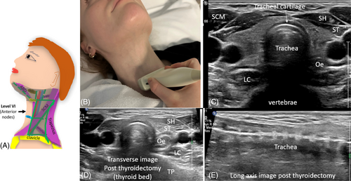
Level VI includes anterior central LNs; pre-tracheal, para-tracheal, peri-thyroidal, pre-cricoid (Delphian) node, as well as LNs along the recurrent laryngeal nerves.3, 18 Para-tracheal LNs sit in the trachea-oesophageal groove, and the peri-thyroidal LNs sit around the thyroid gland.24 Delphian (pre-cricoid or pre-laryngeal) LNs sit superficial to the crico-thyroid membrane, superior to the thyroid isthmus.24 They may be involved in diffuse squamous cell carcinoma of the head and neck or in isolation from laryngeal or thyroid carcinomas.3 Sonographically, when imaging Level VI, an extended field of view can demonstrate all landmarks.24 When the thyroid has been removed, the thyroid bed will be imaged. It is important not to misinterpret the anterior strap muscles for thyroid tissue (Video 4).
10 CONCLUSION
Sonographic imaging of neck LNs is commonly requested. Sonographic imaging and reliable reporting of the status and location of LNs in the head and neck can be a challenge. An understanding of the sonographic distinction between benign and suspicious sonographic neck LNs is firstly required. Knowledge of the surgical neck levels and sonographic landmarks used to demarcate levels for neck LNs is also required. Furthermore, the associated sonographic technique to image and document suspicious neck LNs is also required to accurately inform and guide patient management and surgical treatment.
ACKNOWLEDGMENT
Open access publishing facilitated by Central Queensland University, as part of the Wiley - Central Queensland University agreement via the Council of Australian University Librarians.
CONFLICT OF INTEREST STATEMENT
There are no conflicts of interest to declare.


